Reconstruction
1. Emergency treatment
Emergency treatment in orbital fractures is always indicated in the following situations:
- Partial or complete visual loss due to direct or indirect optic nerve trauma
- Severely increased intraocular pressure
- Acute space-occupying lesion creating increased intraorbital pressure (eg, retrobulbar hematoma, orbital emphysema)
- A severe shift of orbital content
- Severe entrapment of eye muscle (particularly in pediatric patients, “trapdoor”)
Globe rupture and intraocular trauma
These injuries require ophthalmological intervention.
Retrobulbar hematoma
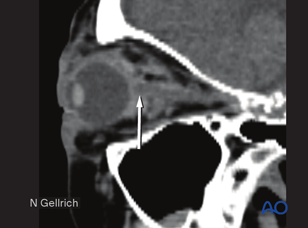
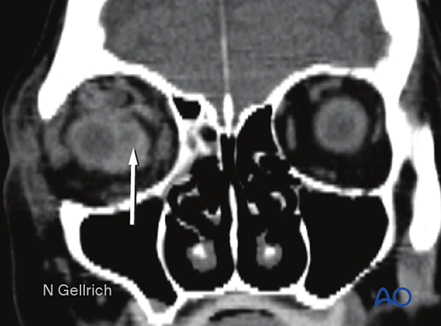
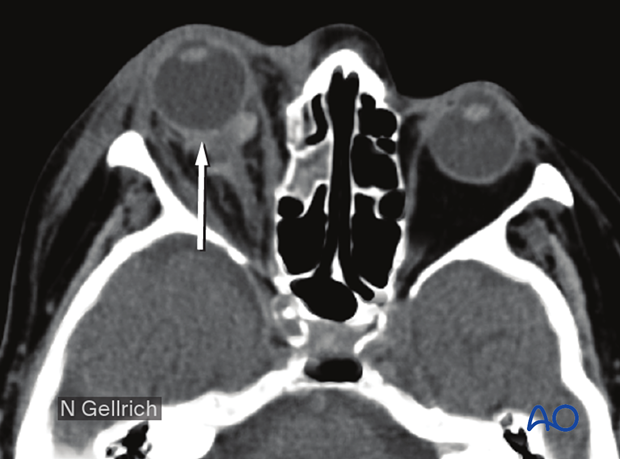
A pressure increase in the periorbital region due to a retrobulbar hematoma can cause significant injury such as the creation of compartment syndrome with injury of the neurovascular structures and the possibility of vision loss.
Read more details about retrobulbar hemorrhage here.
This CT scan sagittal view shows a small retrobulbar hematoma.
Coronal view of the same retrobulbar hematoma.
Axial view of the same retrobulbar hematoma.
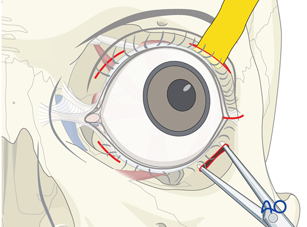
If a retrobulbar hematoma leads to a tense, proptotic globe with acute visual disturbances, emergency decompression should be initiated. This situation requires urgent decompression, such as cantholysis, removal of implanted reconstructive material, and/or evacuation of a loculated hematoma under general or local anesthesia.
Transcutaneous transseptal incisions help evacuate the hematoma and relieve excess periorbital pressure. Alternative methods such as transconjunctival pressure release, lateral canthotomy, and inferior cantholysis may also be considered according to patient condition.
An exception may be pulsatile exophthalmos which can be a sign of a carotid-cavernous sinus fistula. A fistula of this nature requires appropriate preoperative imaging and planning.
Emphysema
Severe emphysema might significantly raise intraorbital pressure. If this compromises visual function or endangers the orbital contents, orbital decompression must be considered.
Patients with signs of intraorbital emphysema are given antibiotics and decongestive nasal drops.
To avoid additional emphysema due to acute pressure rise, patients with sinus fractures in the periorbital region should not blow their nose. They should also be instructed to sneeze with an open mouth to minimize the increase of intranasal/intrasinus pressure.
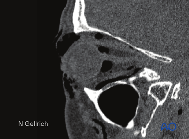
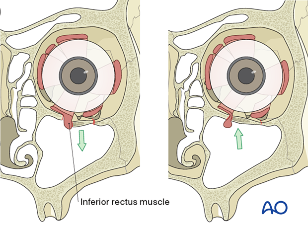
Usually, there is no need for emergency treatment of orbital floor/medial wall fractures unless there is severe ongoing hemorrhage in the orbital cavity, the paranasal sinuses, the nasal cavity, or fractures which create muscle ischemia.
In younger patients there is a danger of necrosis of the entrapped rectus muscle due to the so-called “trapdoor” phenomenon. In such cases, immediate release of entrapped tissues is necessary.
More information on the trapdoor phenomenon can be found in the orbital reconstruction treatment for orbital floor fractures in the Surgery Reference pediatric trauma section.
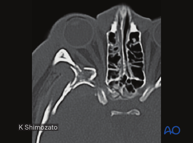
Bone fragments affecting the optic nerve
Special attention should be given to the posterior third of the orbit, the superior orbital fissure, and the optic canal. Fractures and hematoma formation in these anatomical areas can be associated with superior orbital fissure syndrome and optic nerve injury.
In this image the axial CT scan in the plane of the optic nerve shows multiple fractures of the lateral orbital wall and the greater wing of the sphenoid of the right side. Compression or displacement (stretching) of the optic nerve may be produced.
Displaced fracture fragments in the posterior third of the orbit may create nerve compression.
Severe bleeding
In case of severe nasal, oral, or pharyngeal hemorrhage, the following options should be considered:
- Assessment of current medical treatment for anticoagulation such as Coumadin, aspirin, or other antiplatelet medication
- Compression, either by nasal packing, balloon tamponade, or direct compression
- Electrocautery or ligation if a clear bleeding source can be identified
- Normalization of blood pressure
- Interventional radiologic embolization if simpler methods fail
- In some cases, reduction of fracture displacement may significantly reduce bleeding
2. General considerations
Surgical exposure
The key to successful reconstruction of the medial orbital wall is adequate visualization of the defect and precise contouring of the implant.
Management of medial orbital wall fractures has benefited from recently developed surgical approaches (such as the extension of the transconjunctival incision medially) and technological developments such as navigation.
Exposure of medial orbital wall fractures can be very challenging. Transconjunctival lower-eyelid approaches with a medial extension behind the lacrimal system are required to expose the medial orbital wall.
In more complex panfacial fractures, and if the nasoethmoid complex is involved, the medial orbital wall can also be reached through the coronal approach.
The challenge is to use an appropriate approach that provides ideal visualization of the fractures, access for insertion of material, and results in the optimal esthetic outcome. The authors recommend terminating the medial wall dissection at the posterior ethmoidal foramen which is 5 mm anterior to the optic canal.
Alternatively, transcutaneous or transnasal endoscopic approaches will allow partial (transcutaneous) or full (transnasal) visualization. Transnasal approaches require partial or substantial resection of the medial ethmoid sinus complex.
Visualization of fracture
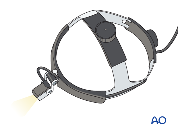
Appropriate exposure of the orbit requires adequate visualization. Wide exposure of the fracture and adequate lighting is essential when addressing these fractures. Consider using headlights for all orbital surgery.
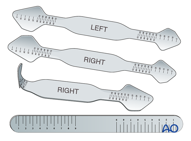
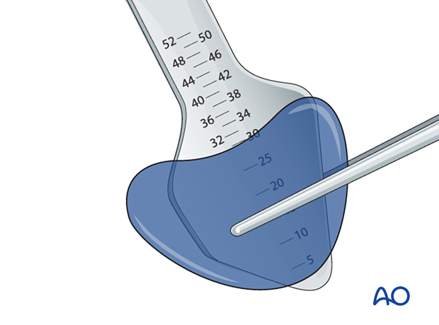
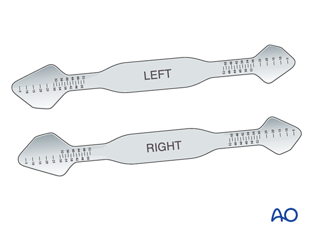
Special malleable orbital retractors (straight or anatomically formed) are available with metric markings that provide the surgeon with additional information regarding the extent of the fracture and the depth of the orbital dissection. Specific orbital retractors have been developed to improve orbital retraction and minimize soft-tissue prolapse during the insertion of implants.
Medial wall
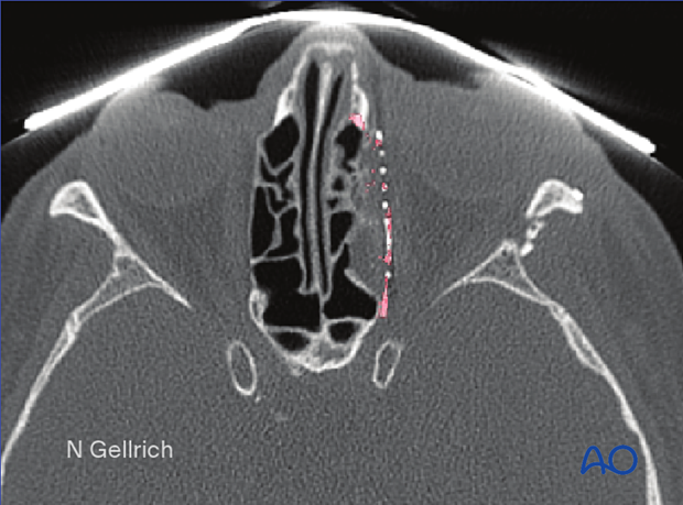
The uninjured medial orbital wall has a bulge towards the orbital contents. This should be mimicked in the reconstruction of the left medial wall. This can be particularly challenging when the medial wall fracture extends posteriorly.
Note the extent of the reconstruction required for this particular medial wall fracture.
3. Choice of reconstruction material
General considerations
Unless prebent plates are used, the unique and complex anatomy of the orbit requires significant contouring of the implants to restore the proper anatomy.
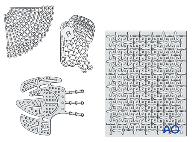
Most cases require reconstruction of the orbital floor to support the globe position and restore the shape of the orbit. Therefore, the concept of orbital reconstruction is facilitated by replacing the missing bone with alloplasts rather than trying to reconstruct by reducing bone fragments. This can be accomplished using various alloplastic materials. The larger the defect, the more the use of contoured implants is indicated. Preformed anatomic implants, either patterned upon averages or patient specific, can facilitate precise restoration of orbital anatomy.
There is hardly any anatomic region in the human body as controversial as this one in terms of appropriate material for use in fracture repair:
- Nonresorbable versus resorbable
- Autogenous/allogeneic/xenogeneic versus alloplastic material
- Non-prebent versus preformed (anatomical) plates
- Standard versus patient-specific plates
- Nonporous versus porous material
- Noncoated versus coated plates
Many surgeons recommend using radiopaque materials that allow bending to a precise anatomical shape and intra- or postoperative radiologic confirmation of placement. These materials should also be stable over time.
The use of resorbable materials is not indicated. Use of resorbable materials may lead to secondary changes of the orbital contours over time, which is undesirable.
There is a paucity of evidence to support the ideal choice for an orbital implant.
Modern imaging analysis offers a unique chance to assess the surgical result and stability over time. This can provide valuable information for future recommendations.
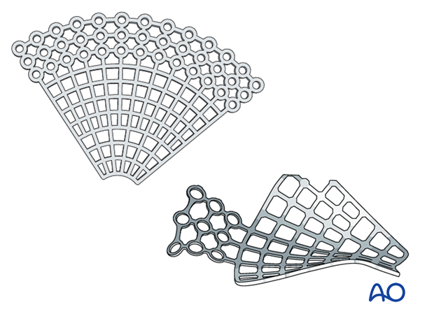
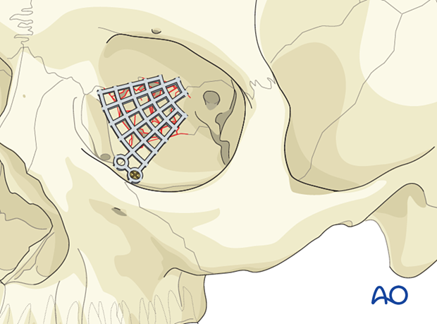
Titanium mesh
Advantages include the following:
- Availability
- Stability
- Contouring (aided using a sterile artificial skull)
- Ideal for large defects or three-wall fractures (the prebent plate is limited to medial wall and orbital wall fractures only)
- Radiopaque
- Spaces within the mesh to allow dissipation of fluids and blood
- No donor site needed
- Tissue incorporation may occur
Disadvantages include the following:
- Cost
- Possible sharp edges if not correctly trimmed
- We do not have long-term experience in a large series regarding the use of metallic mesh in young children. In several pediatric cases starting after the age of four, it proved to be safe.
- The extensive use of mesh for orbital reconstruction in traumatized orbits has been shown to be safe, with few problems due to infections and no issues with secondary displacement due to additional trauma, assuming proper handling, contouring, and fixation of the mesh.
Bone graft
Advantages include the following:
- Low material costs
- Smooth surface
- Variability in thickness
- Radiopacity
- Maximal biocompatibility
- Periorbita readily dissects off from the bone in secondary reconstructions
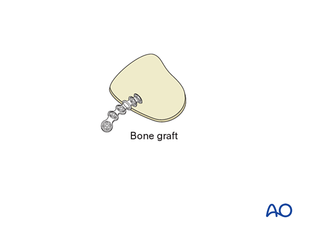
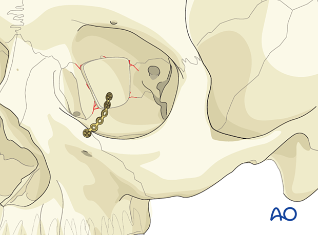
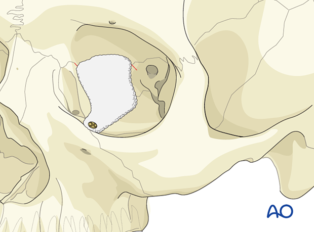
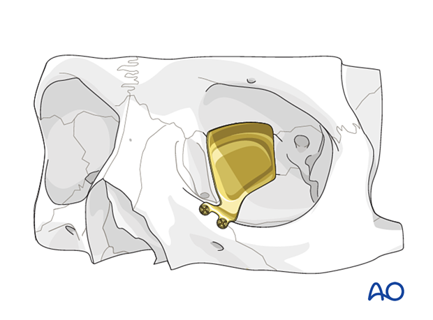
The illustration shows a calvarial bone graft stabilized by a titanium fixation plate.
Disadvantages include the following:
- Additional donor site needed (necessitating extra surgery time for harvest, pain, scar, and possible surgical complications)
- Possible contour and dimensional changes due to remodeling
- Difficult to shape according to patient’s anatomy
- Less drainage from the orbit than with titanium mesh
Porous polyethylene sheets (PPE)
Advantages include the following:
- Availability
- Contouring (eased by a sterile artificial skull)
- Smooth edges
- Allows tissue ingrowth
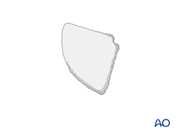
Disadvantages include the following:
- Not radiopaque (not visible on postoperative images)
- Lack of rigidity when a very thin wafer of PPE is used
- When a thicker, rigid wafer is used, there is a risk of causing a dystopia
- Less drainage from the orbit than with titanium mesh
- Difficult to reproduce normal orbital anatomy
Composite of porous polyethylene and titanium mesh
AdvantagesA combination of titanium mesh and porous polyethylene is radiopaque and more rigid than porous polyethylene of a similar thickness. Some surgeons also believe that there is less risk of having retained sharp barbs, which can lead to entrapment of soft tissues during placement. This implant is designed to guarantee retention of a created shape, something which cannot be achieved by regular polyethylene without the memory provided by the titanium.
Other advantages are:
- Availability
- Stability
- Contouring (eased by a sterile artificial skull)
- Adequate in large three-wall fractures (the prebent plate is limited to medial wall and orbital wall fractures only)
- Radiopacity
- No donor site needed
- Tissue incorporation may occur
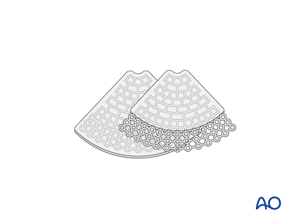
A composite of porous polyethylene and titanium mesh has the following disadvantage:
- Less drainage from the orbit than with titanium mesh
Resorbable materials (thermoplastic and non-thermoplastic)
Advantages include the following:
- Availability
- Handling/contourability (only for thermoplastics)
- Smooth surface and smooth edges
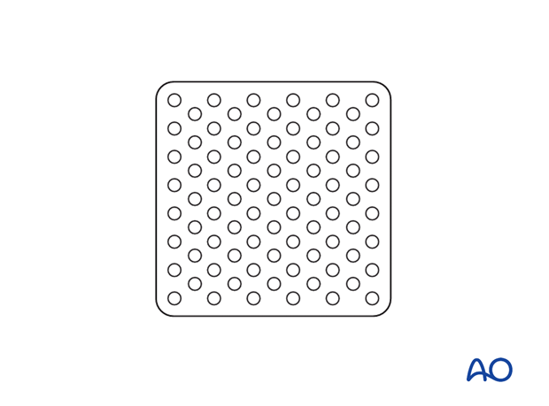
Disadvantages include the following:
- Non radiopaque
- Degradation of material with possible contour changes
- Sterile infection/inflammatory response
- Challenging to shape according to patient’s anatomy (only for non-thermoplastics)
- Non-perforated implants may not allow drainage of fluid or blood from the orbit
- Any material may have sharp edges if not properly contoured
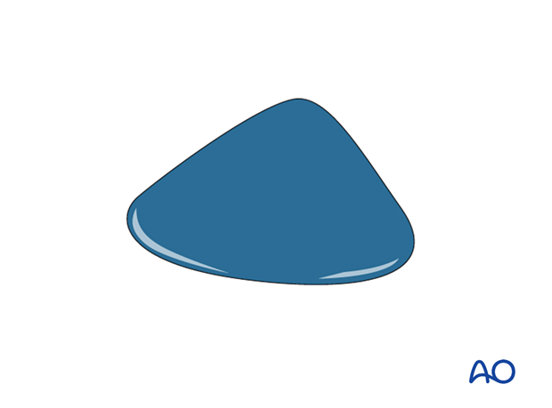
The illustration shows a non-thermoplastic port delivery system (PDS) implant.
Preformed (anatomic) orbital implant
Advantages include the following:
- Radiopaque
- Smooth surface
- Minimal or no contouring is necessary
- Restores normal orbital anatomy
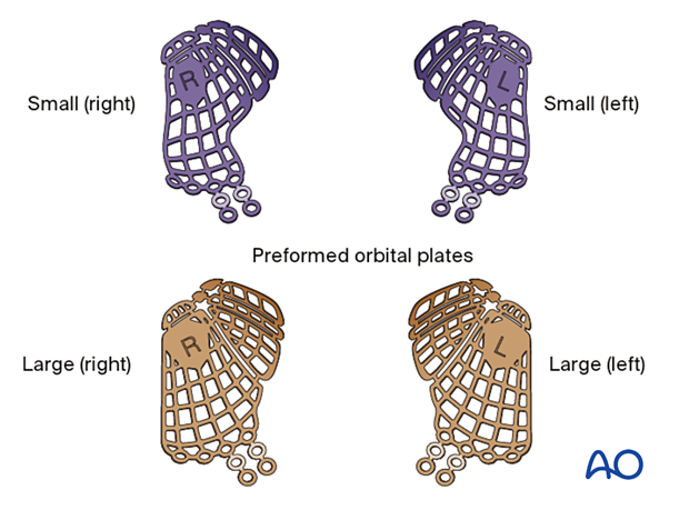
Disadvantages include the following:
- Cost
- May be difficult to properly position
- Each implant represents grouped orbital averages and may not be patient specific
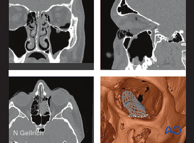
This illustration shows a multiplanar and 3D view of a preformed mesh plate (STL) virtually placed before surgery into a patient CT dataset.
Patient-specific implant
A 3D printed patient-specific implant (PSI) can be manufactured using the patient’s CT data to allow for the precise reconstruction of large orbital defects. Mirroring the uninjured orbit allows for the precise anatomic restoration of the fractured orbit during the planning process.
Advantages include the following:
- Radiopaque
- Smooth surface
- No contouring is necessary
- Perfectly restores normal orbital anatomy
Disadvantages include the following:
- Cost
- Time to manufacture
- Availability
Implant fixation
Fixation of orbital reconstruction material varies according to the type and nature of the fracture.
Fixation of most materials in the orbital floor is achieved using one or more screws. The diameter depends on anatomical requirements but will typically vary between 1.0 and 1.5 mm. Alternatively, other screw types can be used.
4. Surgical exposure
Periorbital dissection
After initial exposure, periorbital dissection is performed.
The following pages provide general information regarding orbital anatomy and dissection:
- Preoperative considerations
- Anatomy of the bony orbit
- Correlation of surface and cross-sectional anatomy
- Introduction to periorbital dissection
- Orbital floor dissection
- Medial orbital wall dissection
- Lateral orbital wall dissection
- Orbital roof dissection
- Adjunctive access procedures (orbitotomies)
- Retrobulbar hemorrhage
Retraction
Adequate exposure (via a combined transconjunctival/retrocaruncular approach with variable extension onto the orbital floor) is facilitated by illumination (headlights, illuminated retractors) of the fractured area.
Adequate hemostasis must be achieved.
Appropriate retraction of the intraorbital soft tissues must be precise and not of excessive pressure, balancing the two requirements of adequate visualization and protection of the orbital contents, by allowing intervals of release of retraction.
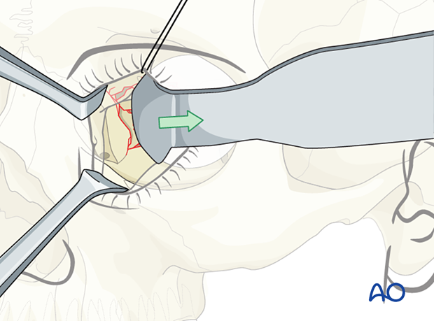
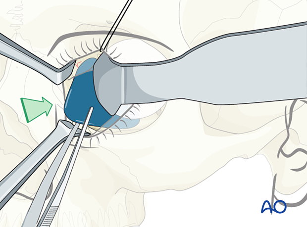
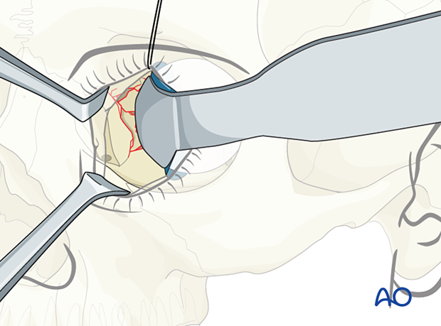
A foil (or sheet of other material) may help with the retraction and avoid prolapse of soft tissues, improve visualization, and prevent entrapment of soft tissues during implant placement.
The illustration shows the insertion of a foil below the retractor.
The retractor is removed, placed under the foil, and the orbital soft tissues are adequately retracted.
Helpful devices
Many devices have been used to facilitate retraction of the orbital contents, including malleable retractors, spoons, and special orbital retractors designed for the globe (as illustrated).
5. Reconstruction
Measurement of defect size and determination of implant size
A careful assessment of the defect size should be performed preoperatively with the CT scan and confirmed intraoperatively by measurement.
Regardless of which fixation is placed over or posterior to the orbital rim, the adjacent soft tissues must not be tethered or pinned by the insertion of the implant. Full muscle excursion must be protected from restriction by the implant. Furthermore, the implant placement must not cause eyelid malposition. This can be avoided by optimizing the size, thickness, position, fit, and fixation of the implant.
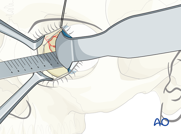
Example of reconstruction with titanium mesh
Firstly, the mesh is cut.
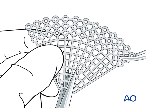
Then all sharp edges of the plate are trimmed off to protect the soft tissues (note the shape of the fan has only a minimum number of screw holes).
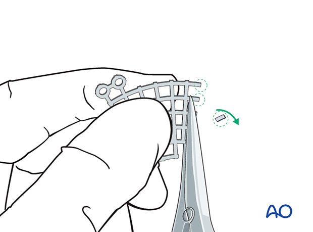
After that, the mesh is contoured to achieve the required shape and accommodate key anatomical structures (nasolacrimal duct, infraorbital nerve, and optic nerve).
It is advisable not to extend the implant further posterior than the posterior ethmoid frame (5 mm anterior to the optic canal).
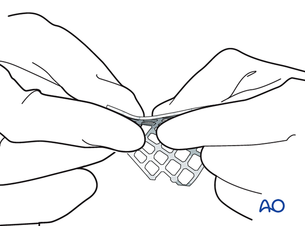
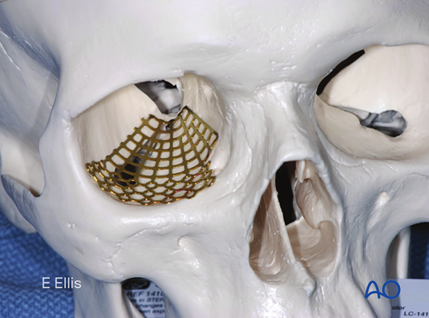
A sterile artificial skull may be used for anatomical contouring of the implant. As shown in this image, the entire implant can be contoured to the shape required for an inferior orbit. This contoured implant can then be used to cover a range of inferior orbital defects. Individual modification of an implant for size, shape and position is always required to fit the needs of the individual patient. The sequence of inserting, measuring, withdrawing, and further modifying the implant can be repeated until an implant of the proper size and shape is produced.
Post-insertion modification may be minimized if a correctly-sized pre-shaped mesh is available.
- When using a fan-shaped plate, be aware that the mesh is designed to cover almost any reconstruction need. The width of the mesh should be modified to fit the defect. It should be as small as possible with the edges of the mesh overlapping the edges of the defect.
- The need for screw fixation varies with the material used and the shape and contours of the anatomic area. As a general principle screw fixation is preferred.
- It is essential to create a plate that is large enough to span the defect and to permit recreation of the contour of the orbit in that location.
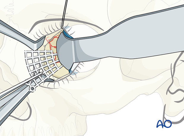
Regardless of the implant chosen, the insertion process must prevent deformation of the mesh. After adequate retraction of the intraorbital soft tissues, the implant is positioned achieving proper stability and reconstruction of the contour of the orbital wall. Care must be taken that no soft tissues (orbital fat or muscles) are entrapped or restricted by the insertion of the implant. During the insertion process, the mesh may require rotation to be correctly positioned. Any perception that the implant is misplaced or improperly aligned should be corrected by removal, modification, and reinsertion of the implant.
Option: Computer assisted surgery
DICOM data can be used to generate 3D virtual models of the patient’s orbit, and a CAD-CAM custom shaped implant can be fabricated.
Further information about Computer Assisted Surgery can be found here.
Navigation
Additionally, navigation may serve for intraoperative control of implant or fragment position.
Modern 3D C-arm technology will further improve intraoperative quality control of implant positioning. Click here for more information.
Endoscopic visualization
Endoscopic visualization, either through the maxillary sinus or intraorbitally, may additionally confirm implant placement and lack of incarceration of periorbital soft tissue.
6. Fixation
Mesh fixation
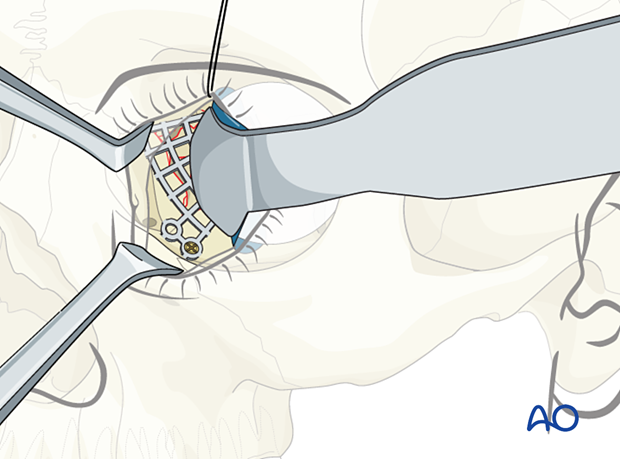
If fixation is required, one screw will suffice in most cases. The screw size must match the chosen mesh type.
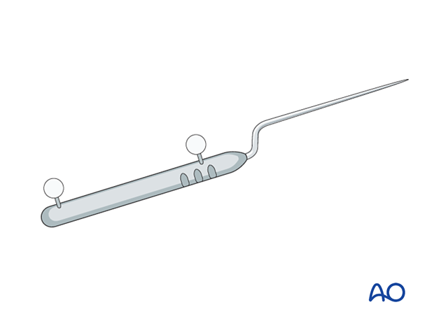
Forced duction test
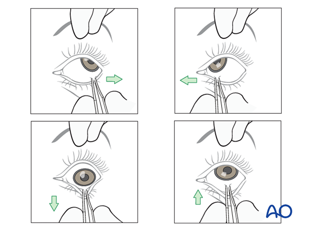
After the insertion of an implant and before closure, it is imperative to perform a forced duction test and to examine the state of the pupil.
Alternative: Bone graft
If bone is harvested from a donor site, eg, cranial vault (parietal area), iliac crest, mandible, rib, etc, there may be donor site morbidity.
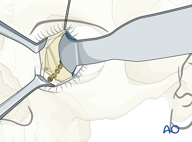
According to the defect dimensions, the bone graft must be adapted and fixed either with screw fixation only or with plate and screw fixation (as illustrated).
7. Aftercare
Evaluation of the patient’s vision
Patient vision is evaluated on awakening from anesthesia and then at regular intervals until hospital discharge.
A swinging flashlight test may serve to confirm pupillary response to light in the unconscious or non-cooperative patient; alternatively, an electrophysiological examination must be performed but this is dependent on the appropriate equipment (VEP).
Postoperative positioning
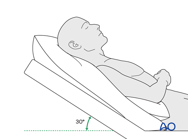
Keeping the patient’s head in a raised position both preoperatively and postoperatively may significantly reduce edema and pain.
Nose blowing
Nose blowing should be avoided for at least ten days following fracture repair to prevent orbital emphysema.
Medication
The use of the following perioperative medication is controversial. There is little evidence to make solid recommendations for postoperative care.
- No aspirin for seven days (nonsteroidal anti-inflammatory drugs (NSAIDs) use is controversial)
- Analgesia as necessary
- Antibiotics: many surgeons use perioperative antibiotics. There is no clear advantage of any antibiotic, and the recommended duration of treatment is debatable.
- A nasal decongestant may be helpful for symptomatic improvement in some patients.
- Steroids, in cases of severe orbital trauma, may help with postoperative edema. Some surgeons have noted increased complications with perioperative steroids.
- Ophthalmic ointment should follow local and approved protocol. This is not generally required in the case of periorbital edema. Some surgeons prefer it. Some ointments have been found to cause significant conjunctival irritation.
Ophthalmological examination
Postoperative examination by an ophthalmologist may be requested. The following signs and symptoms are usually evaluated:
- Vision
- Extraocular motion (motility)
- Diplopia
- Globe position
- Visual field test
- Lid position
- If the patient complains of epiphora (tear overflow), the lacrimal duct must be checked
- If the patient complains of eye pain, evaluate for corneal abrasion
Postoperative imaging
Postoperative imaging must be performed within the first days after surgery. 3D imaging (CT, cone beam) is recommended to assess complex fracture reductions. An exception may be made for centers capable of intraoperative imaging.
Wound care
Ice packs are effective in the short term to minimize edema.
Remove the sutures from the skin after approximately five days if non-resorbable sutures have been used.
Avoid sun exposure and tanning to skin incisions for several months.
Diet
Diet depends on the fracture pattern.
A soft diet can be taken as tolerated until adequate healing of the maxillary vestibular incision.
Clinical follow-up
Clinical follow-up depends on the complexity of the surgery and whether the patient has any postoperative problems.
With patients that have fracture patterns that include periorbital trauma, issues to consider are the following:
- Globe position
- Double vision
- Other vision problems
Other issues to consider are:
- Facial deformity (including asymmetry)
- Sensory nerve compromise
- Problems of scar formation
Eye movement exercises
Following orbital fractures, eye movement exercises should be considered.
Implant removal
Generally, implant removal is not necessary except in the event of infection or exposure.
Follow-up
The patient needs to be examined and reassessed regularly. Follow-up imaging at 3–6 months is helpful to ensure proper pneumatization of the sinuses (particularly, mucocele formation must be ruled out), sealing of the skull base, and stability of fragment position.
Special considerations for orbital fractures
Travel in commercial airlines is permitted following orbital fractures. Commercial airlines pressurize their cabins.
Facial fractures may predispose to Eustachian tube dysfunction due to pharyngeal swelling. Forced air insufflation by holding the nose, closing the mouth and attempting expiration and the use of decongestants can relieve middle ear pressure and drum discomfort.
Mild pain on ascent or descent in airline travel may be noticed. Flying in unpressurized aircraft, such as military planes, should be avoided for a minimum of six weeks.
No scuba diving should be permitted for at least six weeks.


