ORIF - Buttress plate and lag screws
1. Preliminary considerations
Fracture characteristics
Usually, the soft-tissue injury is minimal and therefore, these fractures can often be fixed in one stage. Timing can be crucial. Optimal time is either in the first six hours after injury, or after 4-6 days depending on the soft-tissue swelling.
The fibula can be intact or not. Additional injury of the syndesmotic ligaments must be detected during the operation. It might be necessary to address these injuries as well by suture and/or syndesmotic fixation.
2. Fracture orientation and choice of approach
Introduction
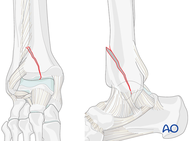
Many pure split fractures of the distal tibia can be approached minimally invasive using stab incisions for the application of reduction forceps and screw fixation. Depending on the fracture pattern, a smaller open approach can be used for the insertion of an antiglide plate.
This latter approach has to be placed in relation to the position of the proximal end of the fracture and can be placed wherever the fracture ends proximally:
- Anteromedial approach
- Anterolateral approach
- Posteromedial approach
- Medial approach
- Posterolateral approach
Interfragmentary lag screws should be inserted from the small fragment to the large intact articular segment of the tibia, providing optimal compression force by the long threaded hole. In the illustrated cases with smaller fractured fragments, plate and screws are inserted from the same direction. With a large fragment, it might be necessary to insert the lag screws at the joint level from the opposite direction of the plate, as shown in the following example. See also the additional material on lag screw principles.
Fracture assessment
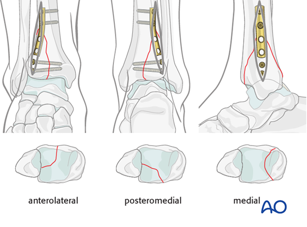
The split fracture can occur in the frontal or sagittal plane, or in between.
The following case demonstrates the surgical management of a partial articular split. The fracture is a large posteromedial fragment of the distal tibia, involving more than 80% of the articular surface. There is a moderate displacement with shortening, resulting in a small intraarticular step and a larger gap. The fracture plane is located between the frontal and sagittal.
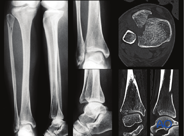
It is combined with a proximal fibular fracture and with a rupture of the anterior syndesmotic ligament.
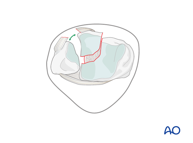
3. Patient preparation
Depending on the approach, the patient may be placed in the following positions:
4. Approach
Posteromedial approach
Since the proximal end of the illustrated tibial fracture is posteromedial, this is where an incision is required. A small posteromedial approach is performed.
After dividing the subcutaneous fat preserving the greater saphenous vein and nerve, the posteromedial tibial crest is exposed by a small longitudinal incision of the fascia of the deep flexor compartment.
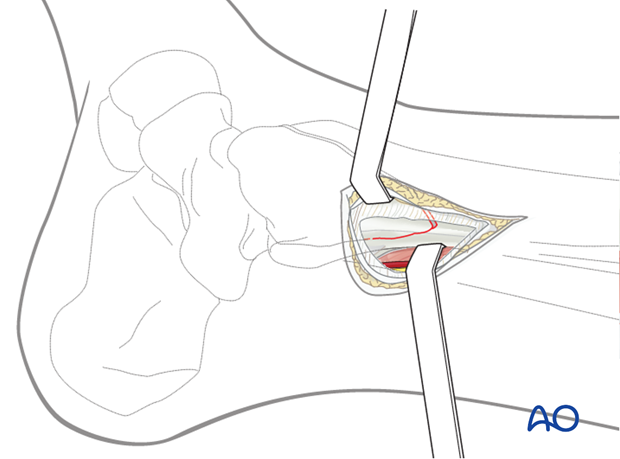
Distal anterolateral approach
A separate small, distal anterolateral approach is helpful to apply a reduction forceps close to the joint and to insert separate lag screws.
Care has to be taken to the superficial peroneal nerve which crosses this approach in a slightly oblique direction.
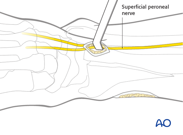
5. Reduction
The fracture line is cleaned.
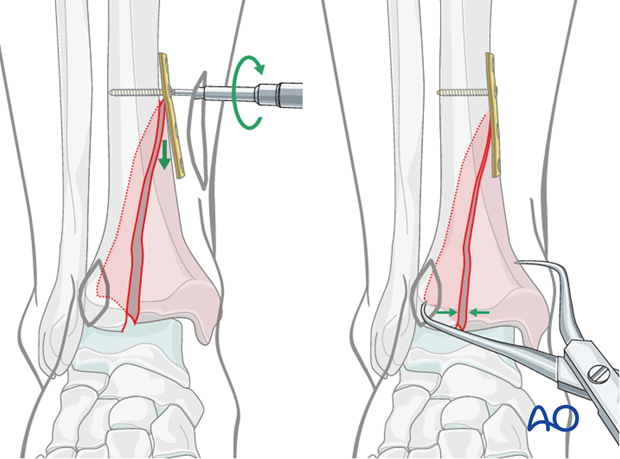
Reduction is achieved by fixation of a one-third tubular plate. The four-hole plate is placed at the level of the proximal end of the fracture, through the posteromedial approach. This plate aids reduction and acts in an antiglide mechanism.
A first screw is placed just proximal to the fracture and tightened, to reduce the fracture by pushing the fractured fragment distally.
The remaining distal gap is reduced with large pointed reduction forceps applied percutaneously. Temporary K-wires can be added if necessary.
The reduction of this large articular piece (red) must be completely anatomical.
Assessment of the reduction can be performed visually at the proximal end of the fracture and by using fluoroscopic control at the joint level. See also the content on assessment of reduction.
6. Insertion of lag screws
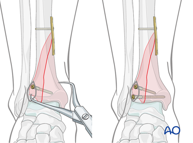
When anatomic position of the fractured fragment is confirmed, lag screws are inserted above the articular surface and perpendicularly to the fracture plane.
In smaller fractured fragments, plate and screws may be inserted from the same side, through a slightly enlarged approach.
See also the additional material on lag screw principles.
Additional stabilization
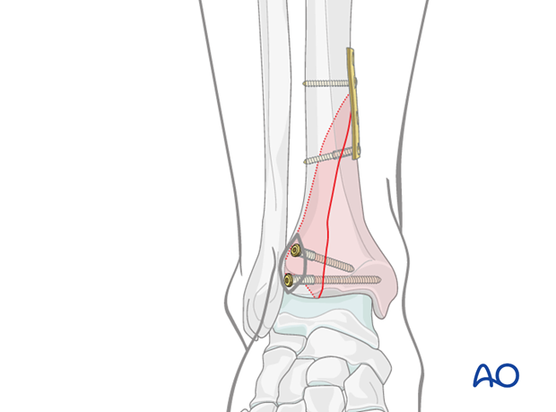
Fracture stabilization is finished with a lag screw through the antiglide plate to prevent a secondary displacement of the proximal end of the large fragment.
7. Assessment of ankle mortise stability
Stability of the ankle mortise (syndesmotic ligaments) has to be checked under fluoroscopic control using the pronation/external rotation test as shown in the illustration. Alternatively, depending on the location and size of the anterolateral approach, the hook test can be performed.
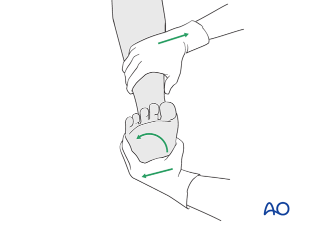
If a syndesmotic disruption is present, there will be rotational instability of the distal fibula with widening, under stress, of the syndesmosis in the anterior part.
Since this is present in the illustrated case, a suprasyndesmotic fibulotibial positioning screw will be added.
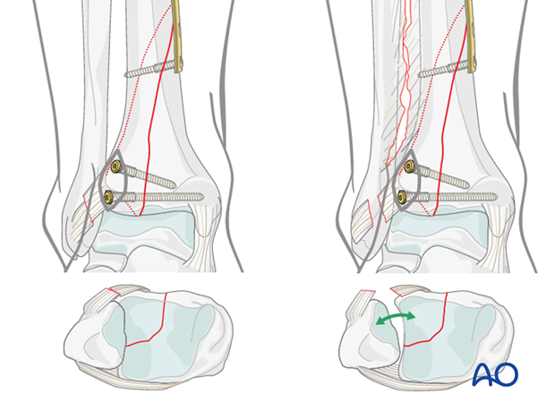
Note: Intraoperative x-rays or image intensification are advised to confirm the position of the screw and the distal tibiofibular joint.
8. Fixation of the syndesmotic complex
After reduction of the fibula at the syndesmosis using either manual compression or percutaneously applied large reduction forceps, introduce the positioning screw through a separate stab incision obliquely from posterior to anterior at an angle of 25–30° and parallel to the tibial plafond. The ankle should be neutral or dorsiflexed during the insertion of this screw.
Place a 3.5 mm cortex screw just proximal to the tibiofibular joint. As this screw is not intended to act as a compressive lag screw, the thread must be tapped in both fibula and tibia.
In complete disruption of the syndesmosis with high instability, two screws are advisable.
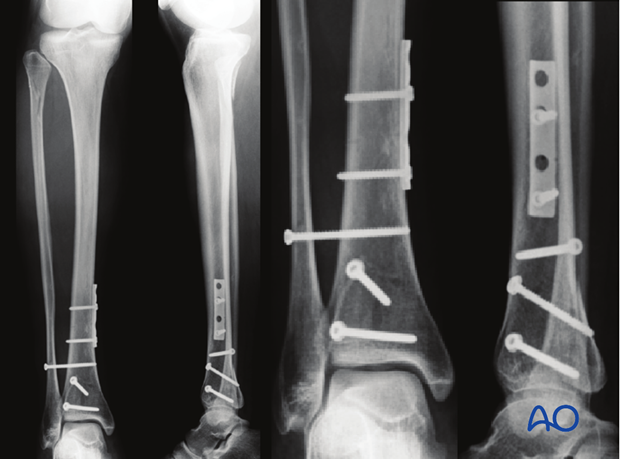
Note: Intraoperative x-rays or image intensification are advised to confirm the position of the screw and the distal tibiofibular joint. See also the content on assessment of reduction.
9. Aftercare
Leg elevation is recommended for the first 2-5 postoperative days. Physiotherapy with active assisted exercises is started at day one.
Mobilization
No immobilization is necessary (in good compliance of the patient). Ambulation with flat foot limited weight bearing (10 kg) (to avoid equinus position of “toe touch”) can be performed after 2-3 days, depending on the soft-tissue swelling.
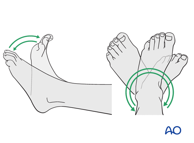
Follow up and implant removal
Follow-up examination after 6 weeks shows still an anatomic position of the tibia and the ankle mortise. At this time, the positioning screw can be removed and increasing weight-bearing with full loading 8-10 weeks after injury can be allowed.
Implant removal may be necessary in cases of soft-tissue irritation by the implant (plate and screws or locking bolts of the nail). The best time for implant removal is after complete remodeling, usually at least 12 months after surgery.
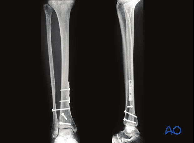
10. Case
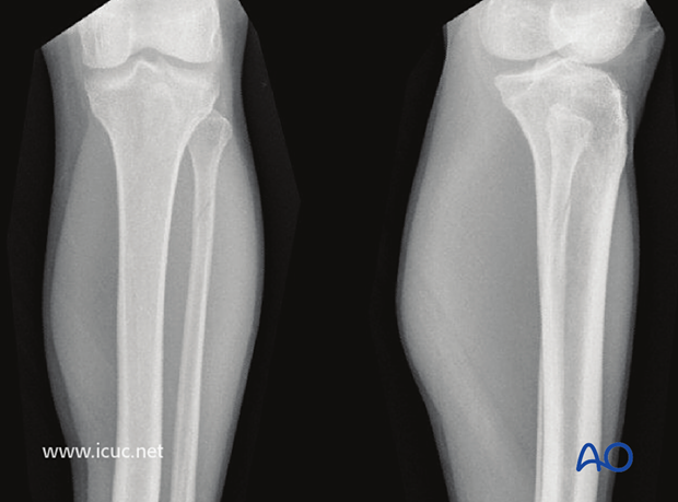
Preoperative AP and lateral X-rays show a Maisonneuve fracture of the proximal fibula in a 25-year-old.
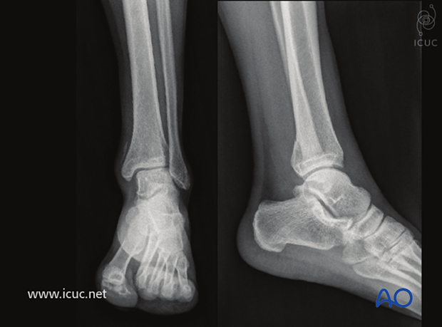
Preoperative AP and lateral X-rays show the posteromedial injury to the distal tibia.
Both the distal and proximal fractures show minimal displacement.
By definition, this fracture pattern involves disruption of the interosseous ligament in the distal tibiofibular joint (syndesmosis). This can be confirmed at the time of fixation, and the syndesmosis should then be stabilized.
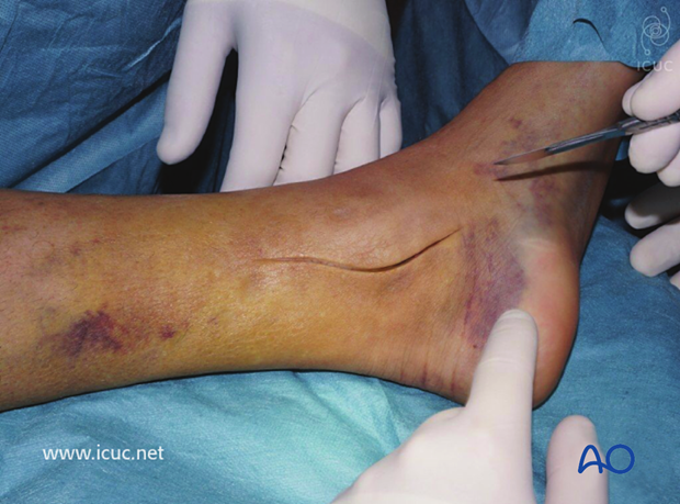
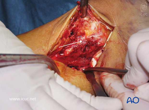
The distal tibia was accessed through a medial incision.
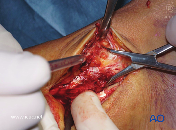
The fracture is not easily seen in this image as a clamp is holding it reduced and it is posterior and hidden by soft tissues.
The non-displaced posteromedial medial malleolar fracture is shown.
A buttress plate was inserted posteriorly.
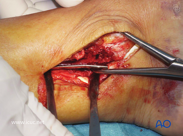
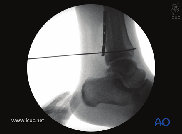
Intraoperative lateral image showing the fracture reduced with the plate in buttressing mode, yet also allowing for screw placement away from the joint.
Proximal screw insertion.
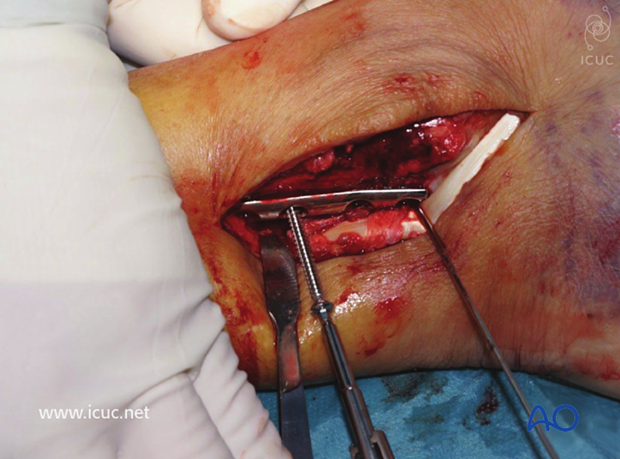
Intraoperative lateral image showing the plate buttressing the posteromedial malleolar fracture.
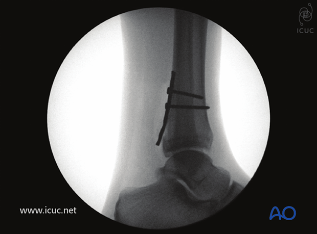
Final lateral image after insertion of distal screw.
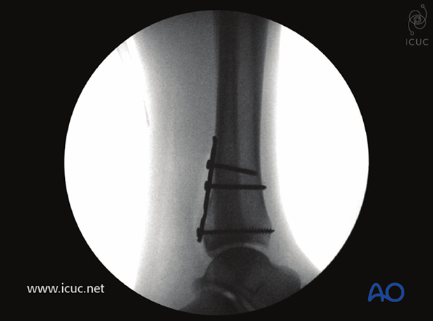
The appropriate location for insertion of a syndesmosis screw was determined using fluoroscopy.
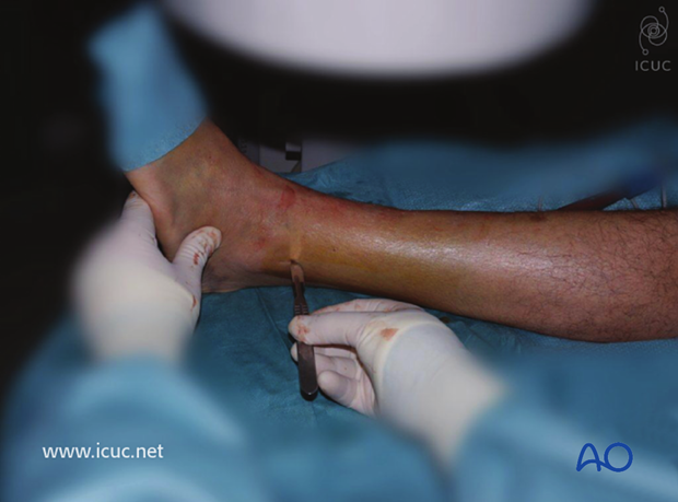
A clamp is placed under fluoroscopy.
It is now advised that the syndesmosis is first visualized open before clamp placement.
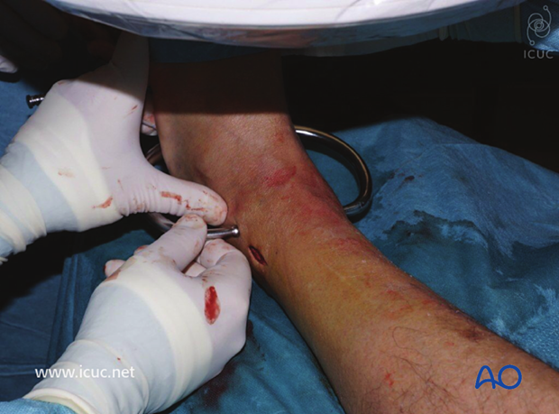
Intraoperative AP image showing the reduced syndesmosis.
The syndesmosis screw is placed about two cm superior to the joint line.
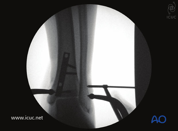
First syndesmotic screw insertion.
The surgeon must be careful not to over compress the syndesmosis when this procedure is performed closed.
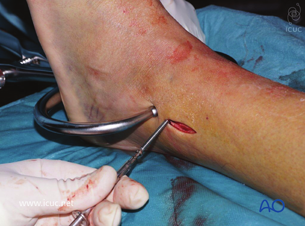
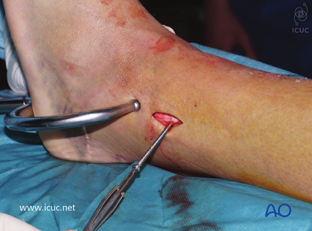
A second syndesmosis screw was inserted.
Intraoperative AP X-ray showing fracture reduction.
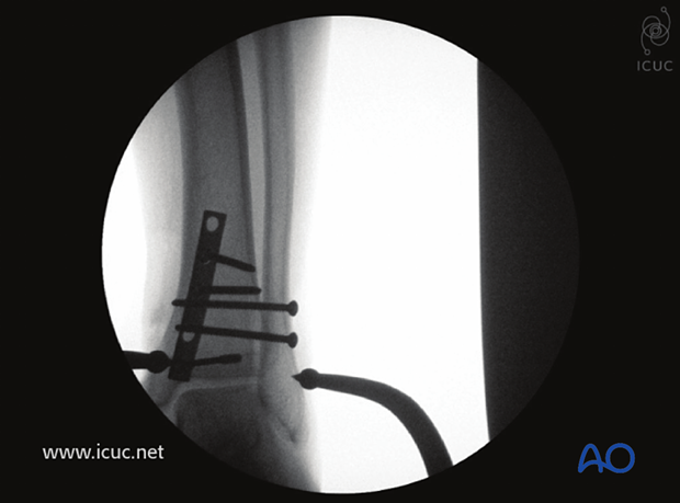
Same as above in lateral view.
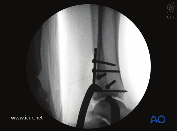
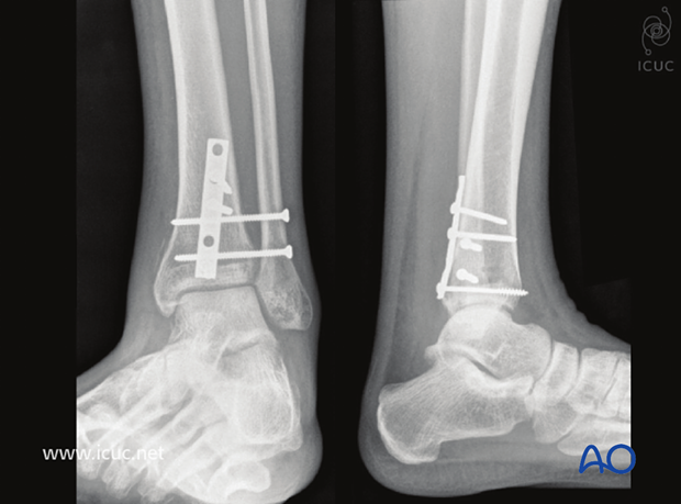
Postoperative AP and lateral view.
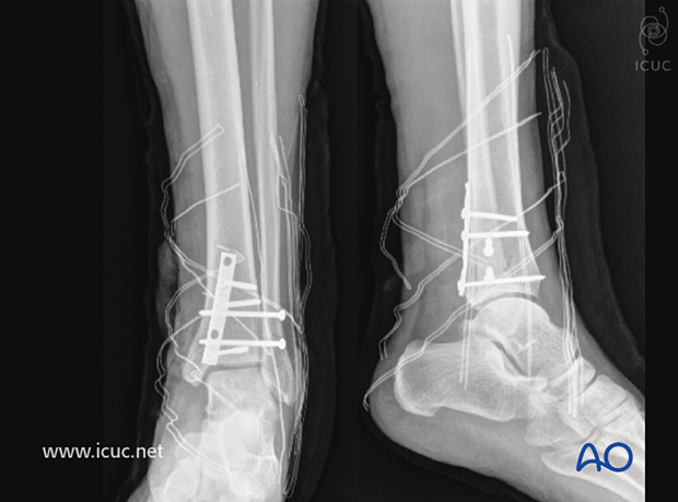
6 weeks postoperative AP and lateral view showing a stable ankle ready for weight bearing.
