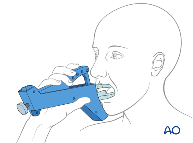
ORIF, two load sharing plates
1. Principles
Plate location
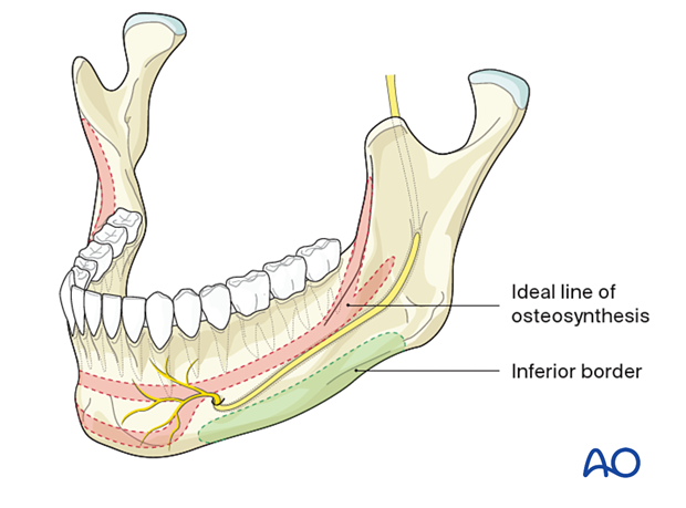
The superior plate is positioned on the ideal line of osteosynthesis.
The inferior plate is located below the course of the mandibular canal (inferior alveolar nerve).
The ideal line of osteosynthesis in the body region runs at the tooth apices' vertical height from the canine region to the oblique line. The line carries into the oblique ridge, which turns into the anterior outer rim of the ramus.
This line is located directly underneath the mucogingival sulcus that can be exposed with ease. The bone thickness of the lateral cortex varies between 6 and 8 mm approximately. Monocortical screws should be less than 6 mm long to avoid injury to the tooth roots.
Biomechanics
Two plates provide more stability than a single plate.
The sequence of plate insertion
The superior plate is inserted first using monocortical screws. This plate stabilizes the fractures and facilitates the inferior plate's fixation, which is more difficult due to poor access.
Special considerations
The following special considerations may need to be considered:
2. Patient preparation
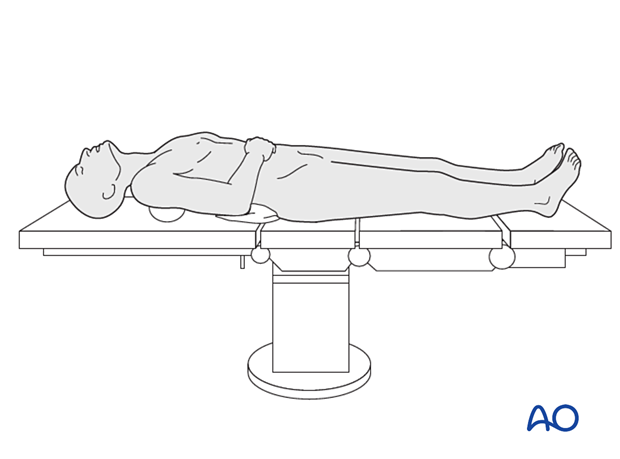
This procedure is typically performed with the patient placed in a supine position.
3. Selection of approach
Surgical approach
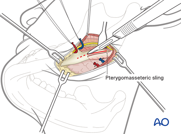
The transoral approach is utilized for the superior plate.
Inferior plate fixation may require a trochar for transcutaneous screw insertion or transoral screw insertion using an angled screwdriver.
Alternatively, a submandibular approach may be used.
4. Choice of implant
Superior plate
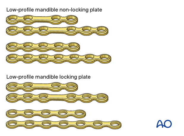
A variety of low-profile mandibular implants can be used superiorly with monocortical fixation:
- 4- or 6-hole mandible locking or non-locking plate with a center space
- 5- or 7-hole mandible locking or non-locking plate without a center space
A locking plate may be used but is usually not required when an inferior locking plate is used.
Inferior border plate
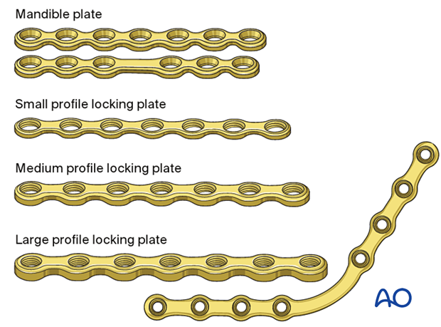
The inferior border plate's profile and type can range from low profile load sharing-plates to larger load-bearing plates (large-sized fracture plates to reconstruction plates).
For simple fractures, the following varieties may be used:
- 5- or 7-hole mandible locking or non-locking plate without a center space
- 4- or 6-hole mandible locking or non-locking plate with a center space
A locking plate will provide better stability and is often used at the inferior mandibular border.
Bicortical screws are used.
Further information
Further information on:
5. Reduction
MMF
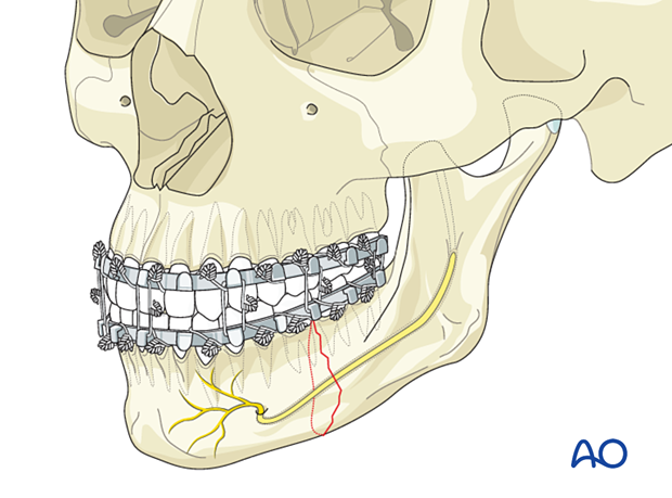
In the isolated mandible body fracture, MMF should be obtained through one of the various means available.
Manual reduction
Reduction of the fragments is performed manually or with the use of elevators or bone hooks. A gross reduction is performed before the MMF application. The precise anatomical reduction is fine-tuned with MMF in place.
Reduction with a conventional bone clamp can be problematic in the posterior region. The clamps can be applied into predrilled holes in the outer cortex that do not interfere with later plate placement.
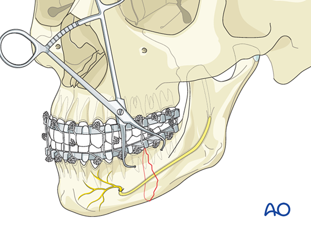
6. Fixation of superior border plate
Plate contouring
Contour the plate according to the surface anatomy of the bone.
Check the plate for precise fitting in situ.
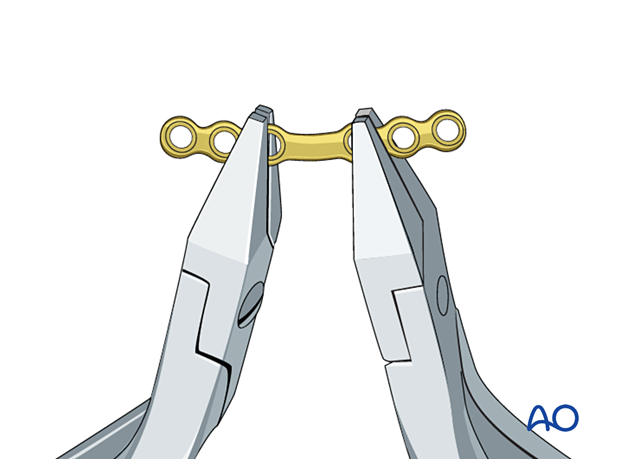
Drill first screw hole
Hold the plate with an appropriate instrument (eg, periosteal elevator or forceps).
Use an appropriately sized drill bit with a 6 mm stop to drill monocortically through the plate hole, next to the fracture line, in the anterior fragment.
The surgeon should be aware that the outer cortex may be very thin. Damage to the tooth roots is still possible even when using a 6 mm drill bit with stop.
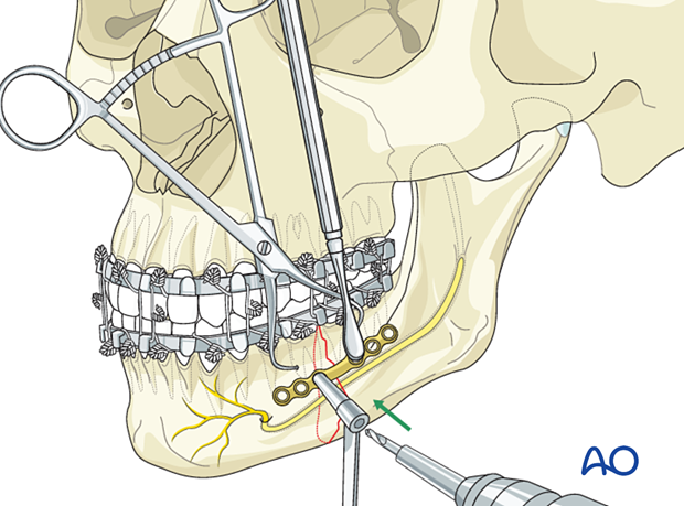
Insert screw
Insert a 6 mm screw. Do not fully tighten it until the final reduction and plate position are confirmed.
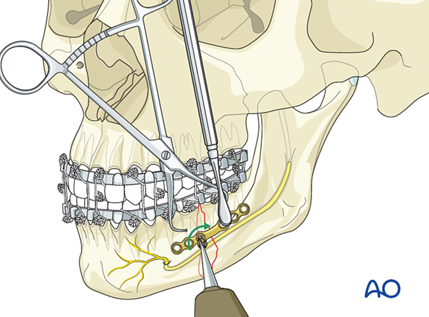
Insert the second screw
Insert the second screw in the hole next to the fracture line in the posterior fragment. The periosteal elevator or any other suitable instrument is used to keep the far end of the plate at the correct vertical level.
Tighten both screws.
If necessary, the clamp can be removed at this stage.
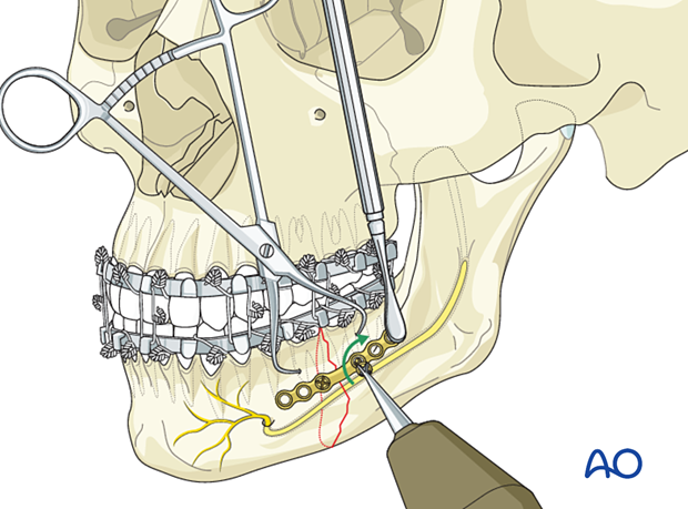
Additional screw insertion
Continue to fill the remaining plate holes in an alternating fashion working your way away from the fracture line.
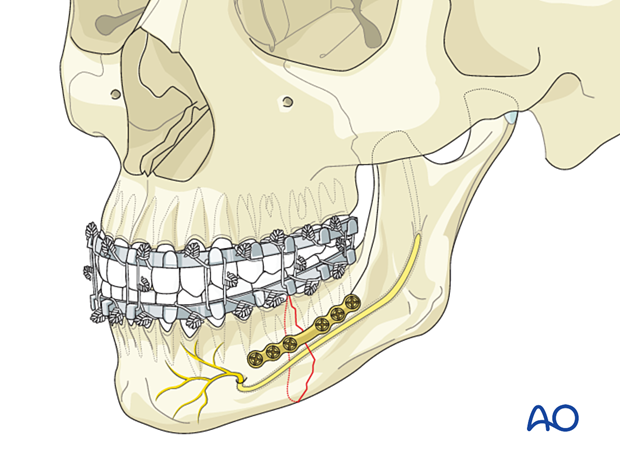
7. Fixation of lower border plate
Plate contouring
According to the profile of the selected plate, the contouring may be more or less technically demanding.
Usually, a straight plate can be inserted at the lower border of the mandibular body. Adjustments to the bony surface must be made by out-of-plane bending.
Using a malleable template or a 3D printed model of the patient's mandible helps contouring larger plate profiles. This approach minimizes the risk of mental nerve injury as repeated plate insertion is avoided.
Correct plate contour and adaptation must be checked either by direct vision or by probing with a blunt instrument.
Ensure the plate's location on the bone over its full length so that all screws will engage in the bone. Improved vision can be obtained using appropriate retractors with fiberoptic lighting or headlights. Alternatively, some surgeons advocate the use of an endoscope.
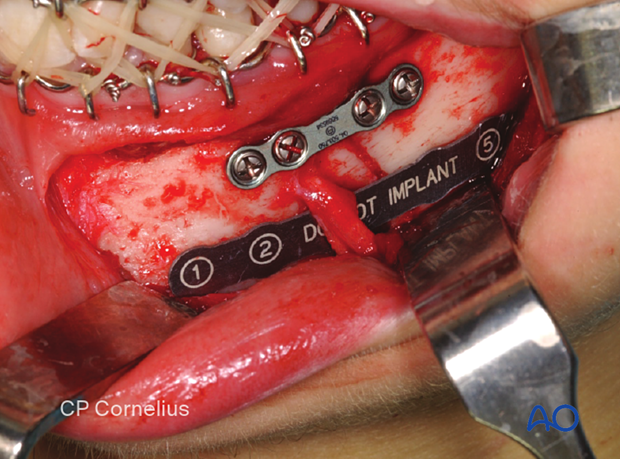
Plate insertion
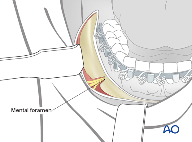
An obstacle to plate insertion is the exiting branches of the mental nerve. The bone region below the nerve branches must be dissected carefully. The plate is positioned in the area below the mental foramen. The nerve branches must be mobilized out of the field during the introduction of the plate. During screw insertion in the mental nerve area, the nerve branches must be protected, and bicortical screws inserted at least 5-6 mm caudal to the mental foramen.
Transbuccal instruments may be needed for proper posterior screw insertion.
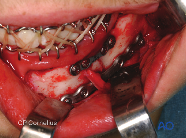
Drill first screw hole
Hold the plate with an appropriate instrument (eg, periosteal elevator or forceps)
Use an appropriate drill bit to drill through the plate hole next to the anterior fragment's fracture line.
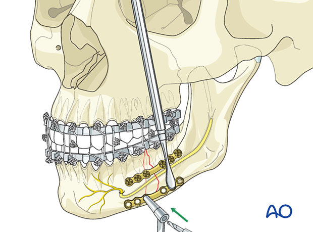
Insert the first screw
Determine the appropriate screw length using a depth gauge. A screw slightly longer than the measured screw length may be used to achieve full screw purchase in the inner cortex.
Insert a screw of appropriate length.
Do not fully tighten it until the final reduction and plate position are confirmed.
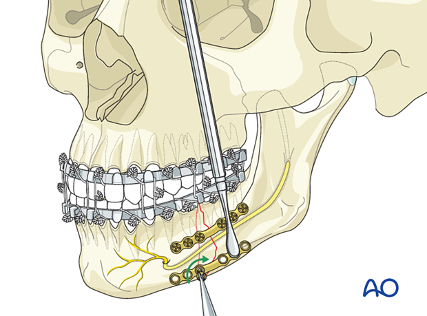
Insert the second screw
Insert the second screw in the first hole on the other side of the fracture line. The elevator is used to keep the far end of the plate at the correct vertical level.
Tighten both screws.
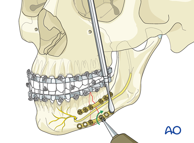
Additional screw insertion
Continue the insertion of the remaining screws in an alternating fashion working your way away from the fracture line.
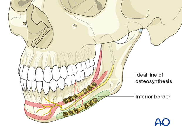
Final check
Release the MMF and check the occlusion for accuracy and the bony surfaces for precise anatomic reduction.
8. Examples of completed osteosynthesis
General remarks
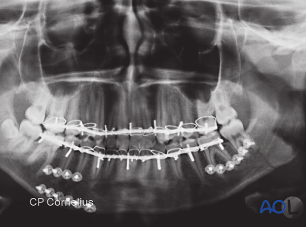
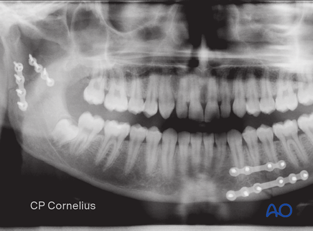
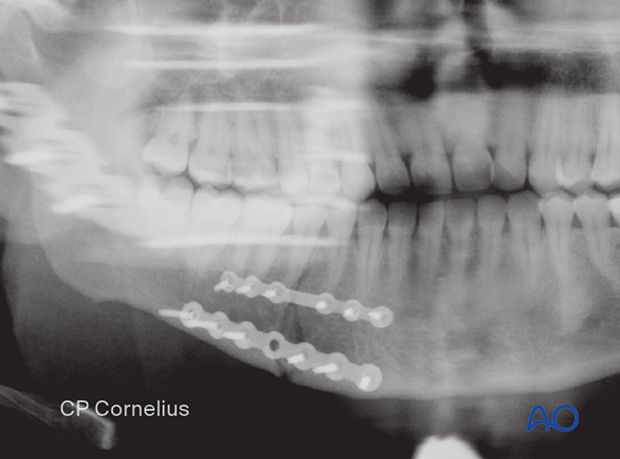
The following X-rays show several completed osteosyntheses in the mandibular body region. In all cases, there are associated fractures in other parts of the mandible.
Case 1:
The right anterior body fracture was fixed with two conventional miniplates.
The left-sided posterior body fracture was stabilized with a single superior border plate and monocortical screws.
Case 2:
Two small profile locking plates were used in this simple left mandibular body fracture.
Note the additional fracture in the contralateral condylar process.
Case 3:
X-ray showing the fixation of a right mandibular body fracture by two locking plates. A small profile plate subapical and a larger one at the inferior border.
9. Aftercare following ORIF of mandibular symphysis, body, angle, and ramus fractures
Use of jaw bra
If significant degloving of the soft tissues of the mandible has occurred, there may be a consideration for using a jaw bra or similar support dressing.
Arch bars
If arch bars or MMF screws are used intraoperatively, they are usually removed at the conclusion of surgery if proper fracture reduction and fixation have been achieved. Arch bars may be maintained postoperatively if functional therapy is required or if required as part of the fixation.
X-Rays
Postoperative x-rays are taken within the first days after surgery. In an uneventful course, follow-up x-rays are taken after 4–6 weeks.
Follow up
The patient is examined approximately 1 week postoperatively and periodically thereafter to assess the stability of the occlusion and to check for infection of the surgical wound. During each visit, the surgeon must evaluate the patient's ability to perform adequate oral hygiene and wound care and provide additional instructions if necessary. Many patients need to be seen regularly for replacement of their intermaxillary elastics and to encourage range of motion in their TMJ in the later course of the treatment.
Follow-up appointments are at the discretion of the surgeon and depend on the stability of the occlusion on the first visit. If a malocclusion is noted and treatable with training elastics, weekly appointments are recommended.
The patient should be warned to continue routine follow up with their dentist. Fractures near the dental roots can often result in delayed loss of tooth viability, requiring periapical films and additional dental procedures.
Malocclusion
If a malocclusion is detected, the surgeon must ascertain its etiology (with appropriate imaging technique). If the malocclusion is secondary to surgical edema or muscle splinting, training elastics may be beneficial. The lightest elastics as possible are used for guidance, because active motion of the mandible is desirable. Patients should be shown how to place and remove the elastics using a hand mirror.
If the malocclusion is secondary to a bony problem due to inadequate reduction or hardware failure or displacement, elastic training will be of no benefit. The patient must return to the operating room for revision surgery.
Basic postoperative instructions
DietDepending upon the stability of the internal fixation, the diet can vary between liquid and semi-liquid to “as tolerated”, at the discretion of the surgeon. Any elastics are removed during eating.
Patients having only extraoral approaches are not compromised in their routine oral hygiene measures and should continue with their daily schedule.
Patients with intraoral wounds must be instructed in appropriate oral hygiene procedures. The presence of the arch-bars and any elastics makes this a more difficult procedure than normal. A soft toothbrush (dipping in warm water makes it softer) should be used to clean the surfaces of the teeth and arch-bars. Any elastics are removed for oral hygiene procedures. Chlorhexidine oral rinses should be prescribed and used at least three times each day to help sanitize the mouth. Chlorohexidine may cause staining of the teeth and should not be used longer than necessary. For larger debris, a 1:1 mixture of hydrogen peroxide (0.25%)/chlorhexidine (0.12%) can be used. The bubbling action of the hydrogen peroxide helps remove debris. A water flosser, providing a water jet, is a very useful tool to help remove debris from the wires. If a this is used, care should be taken not to direct the jet stream directly over intraoral incisions as this may lead to wound dehiscence.
Physiotherapy can be prescribed at the first visit and opening and excursive exercises begun as soon as possible. Goals should be set, and, typically, 40 mm of maximum interincisal jaw opening should be attained by 4 weeks postoperatively. If the patient cannot fully open his mouth, additional passive physical therapy may be required such as Therabite® or tongue-blade training.
