ORIF - Lag screw (epiphysis); MIO - Bridge plate (metaphysis)
1. Introduction
Comment on illustrations
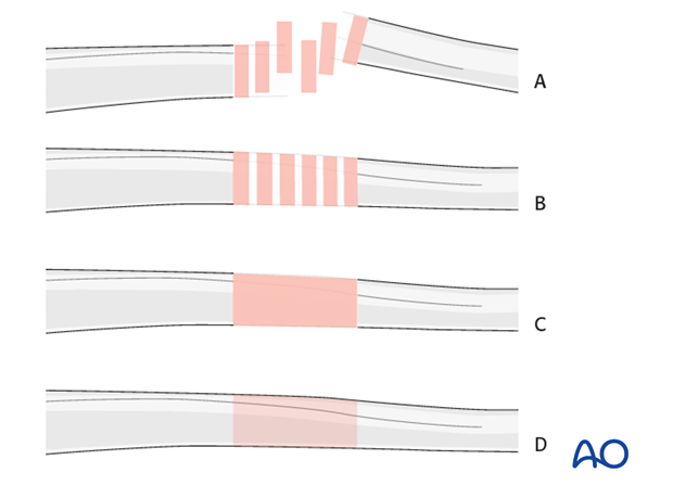
Throughout this treatment option illustrations of generic fracture patterns are shown, as four different types:
A) Unreduced fracture
B) Reduced fracture
C) Fracture reduced and fixed provisionally
D) Fracture fixed definitively
Principles
Complete articular fractures are treated in two main steps.
- Reconstruction of the articular block.
- Reduction and fixation of the articular block to the femoral shaft using the plate.
By placing and fixing the plate in the appropriate position on the distal femur, the correct alignment (varus/valgus) is established when the plate is brought down to the proximal femoral shaft.
For the fragmented diaphyseal component, length, alignment, and rotation must be achieved with bridge fixation independently of which implant is chosen.
Main deformities
In general, three major deformities must be managed when performing fixation of the distal femur with condylar VA-LCP:
- Varus/valgus: The frontal plane alignment is determined by the fixation of the femoral articular block to the condylar VA-LCP with the distal locking screws. If the central 7.3 mm screw in the plate is parallel with the tibiofemoral joint surface, this ensures appropriate varus/valgus alignment.
- Rotation: Careful monitoring of the rotation of the limb is observed throughout the operative procedure. The rotation becomes established once a distal screw and a proximal screw have been inserted.
- Flexion/extension (sagittal plane alignment): The alignment of the Condylar VA-LCP on the lateral aspect of the distal femur establishes the presence or absence of any extension or flexion deformity at the fracture site. After the plate fixation to the distal femur, the flexion/extension relationship becomes established (“locked-in") once a second screw is placed in the proximal main femoral fragment.
Hyperextension deformity
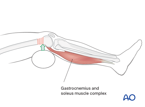
The gastrocnemius typically causes a hyperextension deformity of the distal femoral articular block.
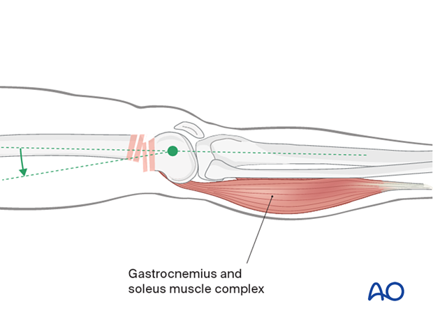
Hyperextension deformity must be corrected before fracture fixation. Aids to correcting this hyperextension deformity include:
- Muscle relaxation of the patient
- A bolster in the supracondylar region
- Flexion of the operating table leg segment
Anatomy of the distal femur
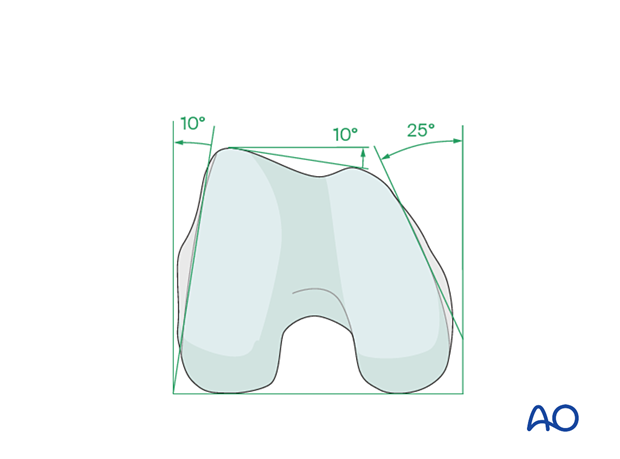
The distal femur has a unique anatomical shape. Seen from an end-on view, the lateral surface has a 10° inclination from the vertical, while the medial surface has a 20–25° slope.
A line is drawn from the anterior aspect of the lateral femoral condyle to the anterior aspect of the medial femoral condyle (patellofemoral inclination) that slopes approximately 10°. These anatomical details are important when inserting screws. In order to avoid joint penetration, these devices should be placed parallel to both the patellofemoral and femorotibial joints planes.
The muscle attachments to the distal femur are responsible for the typical displacement of the distal articular block following a supracondylar fracture, namely shortening with varus and extension deformity. Shortening is due to the pull of the quadriceps and hamstring muscles, while the varus and extension deformity is caused by the unopposed pull of the adductors and gastrocnemius, respectively.
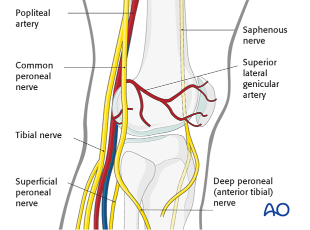
The popliteal vessels, the tibial nerve, and the common peroneal nerve lie near the posterior aspect of the distal femur. Because of this, vascular injuries occur in about 3% and nerve injuries in about 1% of fractures of the distal femur.
There are no significant arteries, veins, or nerves on the lateral side of the knee.
There may be bleeding from the lateral genicular arteries, which will need to be controlled using diathermy.
At the posterior aspect of the knee lie the popliteal artery, nerve, and vein. It must be borne in mind that these structures can be damaged by the injury or can be damaged by the surgeon during the reconstruction.
2. Plate selection
Comparison of distal femur implants
The distal-most fixation for various implants is:
- LISS plate: subchondral
- Condylar variable angle locking compression plate (VA-LCP): subchondral
- 95° angled blade plate: 1.5 – 2 cm from the joint
- 95° dynamic condylar screws: 2 cm from the joint
- Retrograde intramedullary nail: variable depending on the vendor. Please be familiar with the nail you will use to ensure you have sufficient distal fixation.
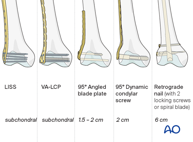
Plate selection
We will here demonstrate the application of the VA-LCP.
Teaching video
Plate length/number of screws
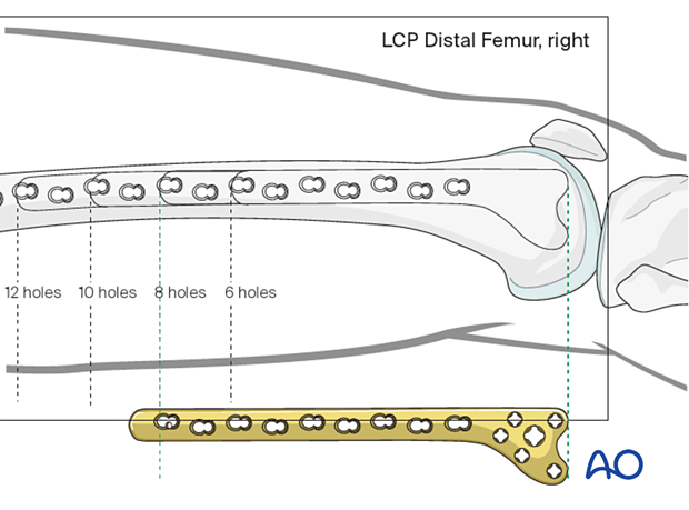
When a relative stability construct is chosen, sufficient proximal fixation of the plate should be obtained. This typically involves four screws.
The number of screws placed in the distal end of the plate should be sufficient to provide appropriate fixation to the distal articular block. A minimum of four screws is typically chosen.
When a relative stability construct is chosen, the plate length should be at least three times as long as the zone of fracture. Nevertheless, most surgeons prefer to apply a plate that spans the entire length of the femur, at least up to the level of the vastus ridge. Bridge plate technique principles should be adhered to where up to 40-50 % of screw holes are filled.
The preoperative x-ray planning template is useful in determining the required length of the condylar VA-LCP and the position of the screws.
3. Patient preparation and approach
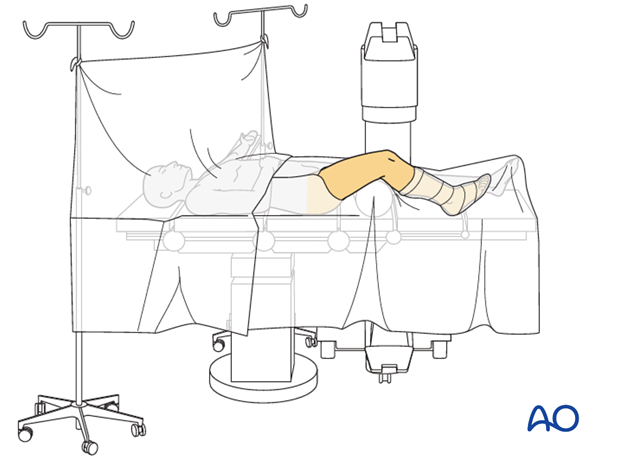
Positioning
This procedure may be performed with the patient in one of the following positions:
- Supine position knee flexed 30°
- Supine position knee flexed 90°
- Lateral decubitus (particularly in obese patients)
Approach
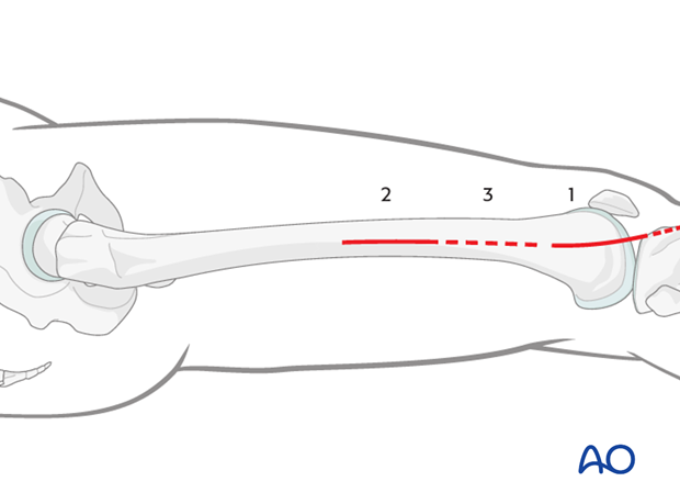
The MIPO approach for complete articular fractures is more complex because the articular block is fractured. Usually, a lateral parapatellar incision allows access to the end segment. In some situations, medial parapatellar or modified parapatellar approach may be used to obtain reduction and insert screws.
Once multiple lag screws are applied (being careful to keep these screws away from the anticipated footprint of the VA-LCP), the plate is inserted through a lateral minimally invasive approach (or the lateral parapatellar approach if this was used for reduction and fixation of the articular block) .
The small opening directly lateral over the end segment should be only as large as to allow the insertion of the VA-LCP implant.
Proximally, small incisions on the side of the thigh laterally are used, but only enough to allow for the insertion of individual screws.
4. Reconstruction of the articular block
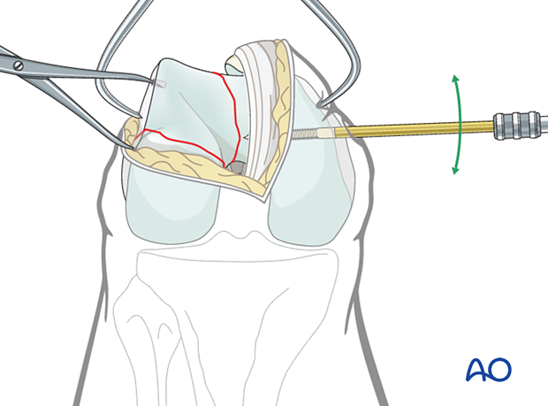
Reduction of the articular block
The chosen approach must adequately expose the articular surface of the distal femoral condyle.
Reduction aids which are helpful include:
- A 5.0 mm or 6.0 mm Schanz pin in the medial and/or lateral femoral condyle to act as a joystick.
- Pointed reduction forceps, or large pelvic reduction clamps, to clamp from medial to lateral across the intercondylar split.
- Modified pointed reduction forceps on the medial or lateral aspect of the femoral condyles to help reduce frontal plane fractures (Hoffa fractures). The pointed reduction forceps are modified by straightening the curved tips. The straightened tips can then be placed in small 2.0/2.5 mm drill holes in the bone. Occasionally fixation must be applied from posteromedial or posterolateral to buttress these Hoffa fractures.
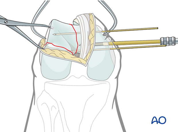
Provisional fixation
Before definitive fixation is undertaken, more than one forceps is applied. Usually, one to two additional K-wires are inserted, either from medial to lateral, or lateral to medial.
If the K-wires are inserted from medial to lateral, they may either go through small stab incisions in the skin or through the parapatellar retinaculum.
Definitive articular surface fixation
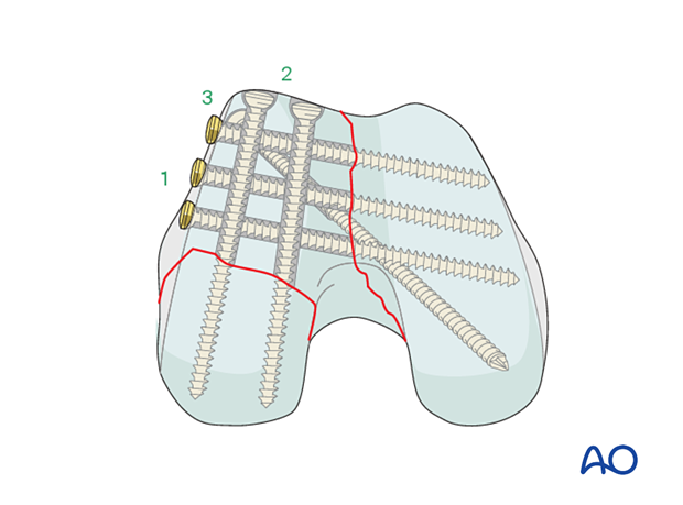
Definitive lag screws may then be inserted in the distal femoral articular block in several directions:
- Screws may be inserted along the periphery of the articular surface of the lateral femoral condyle going from lateral to medial to fix the intercondylar split.
- Screws may be inserted starting just proximal to the articular surface and aimed from anterior to posterior to fix the frontal plane fracture (Hoffa fracture). Buttress plating of the Hoffa fracture or posterior to anterior inserted screws is biomechanically superior.
- A diagonally inserted screw may be used in certain fracture patterns.
These screws may be fully threaded 2.7 or 3.5 mm lag screws (shown with gliding hole), 6.5mm partially threaded lag screws, or 4.0/4.5 mm cannulated partially threaded lag screws.
Insertion of screws in this manner leaves an area free of screw traffic or a „free zone“ of bone into which a laterally based plate system can be inserted (dotted circle). Insertion of screws in this manner allows a „free zone“ of bone into which the plate can be placed (dotted circle).
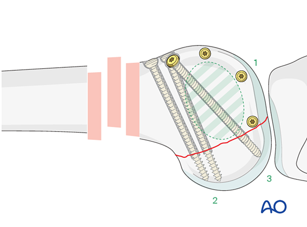
End-on view of the articular block fixation.
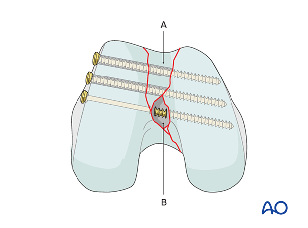
Multifragmentary articular fracture
Multifragmentary articular fractures may also be characterized with or without a Hoffa injury.
In this case, separate osteochondral fragments are ideally reduced and internally fixed by lag screws. However, in certain cases, the fragment may be either too damaged or too small to be reconstructed. In this case, if a fragment is removed, a position screw rather than a lag screw should be used to avoid over-compression of the articular surface.
In the case shown fragment A has been reduced into the appropriate position. This makes it possible to compress the articular surfaces with lag screws. However, fragment B was too damaged and too small to be accurately repositioned. A void is therefore left in the articular surface. In this situation, a fully threaded 3.5 mm standard screw (position screw) is then inserted between the condyles.
Comment on further illustrations
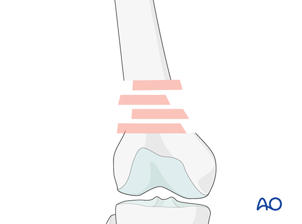
After reconstruction of the articular block, the fracture can be considered a metaphyseal fracture and treated accordingly. In the following illustrations the articular fracture component and it's fixation will not be illustrated.
5. Reduction of the metaphysis/diaphysis
Reduction aids
Closed reduction is aided by:
- Complete anesthetic muscle relaxation
- A bolster in the supracondylar region to reduce the hyperextension deformity of the distal femoral articular block.
- Manual traction
- Femoral distractor

Reduction can also be aided by:
- Use of Schanz pins inserted into the medial, or lateral, femoral articular block to correct varus or valgus angulation of the femoral block.
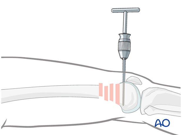
- Insertion of a Schanz pin from anterior to posterior in the distal femoral articular block, which can be used to correct hyperextension.
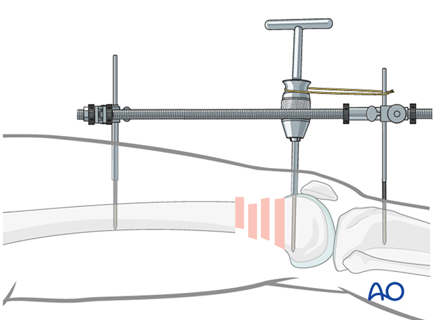
Use of external fixator/femoral distractor
Some surgeons find it useful to use an external fixator (or femoral distractor) from the proximal femur to the proximal tibia.
Due to the pull of the gastrocnemius muscle, the distal fragment tends to be displaced into extension at the metaphyseal fracture area, when distraction is applied.
To avoid this, the knee is brought into full extension, and the distal femoral fragment is stabilized in this position to the tibia. A Schanz screw is inserted in the distal femoral articular block and used to counter the pull of the gastrocnemius. When reduced, a temporary cerclage wire is used to lock the position of the Schanz screw relative to the distractor.
Insert the proximal and distal fixator (distractor) pins carefully in order not to conflict with the later plating procedure. Safe positions would be anterolateral or anterior on the femur.
Verification of successful reduction
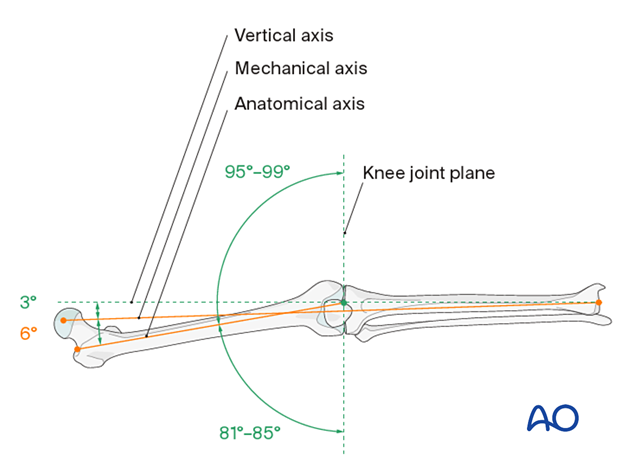
It is very important to restore the biomechanical axis of the lower limb. The normal biomechanical axis follows a line from the center of the femoral head, through the center of the proximal tibia and then through the center of the ankle joint. This axis can be checked intraoperatively by using a piece of cable, such as the diathermy cord. The cord is stretched from the iliac spine across the patella to the cleft between the first and second toes.
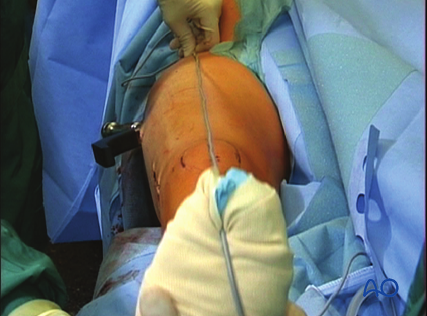
If rotation is correct, this cord will pass over the midline of the patella, and slightly medial to the tibial eminence. The radiological landmarks of the center of the femoral head, the center of the knee and the center of the ankle joint should all be in line if the mechanical axis of the femur is correct.
Another method of assessing rotational reduction is to compare the cortical thickness above and below the fracture. If a shaft fracture is multifragmentary, the image intensifier cannot be used to compare cortical diameters on each side of the fracture.
Not only must the biomechanical axis be restored, but care should be taken to ensure that there is no malrotation of the distal femur on the proximal femur.
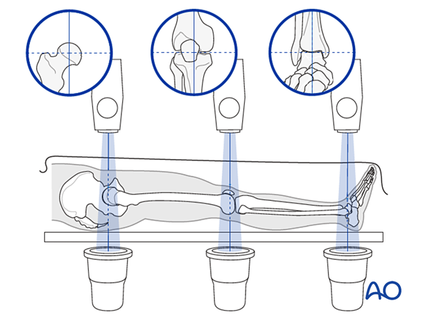
This illustration shows the longitudinal axes of the lower limb.
Confirmation of length
To ensure that femoral length has been restored, many options exist:
- One option involves reducing the fracture fragments anatomically, either directly or indirectly with fluoroscopic control.
- Even in multifragmentary fractures, there are usually a few main fracture segments that can assist the surgeon in ensuring that the appropriate length has been obtained.
- Another option involves taking radiographic images of the contralateral distal femur for comparison.
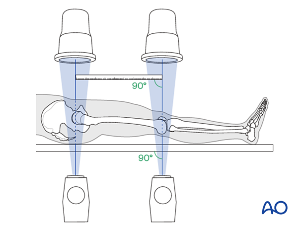
- A radiographic ruler can be used to measure the length of both femora. In this technique, it is important that the x-ray beams are perpendicular to the OR table and that the ruler is parallel to the OR table.
6. Plate insertion
Condylar VA-LCP insertion
Screw the threaded wire guides for the 2.5 mm guide wires into the 5.0 mm and 7.3 mm screw holes of the plate head.
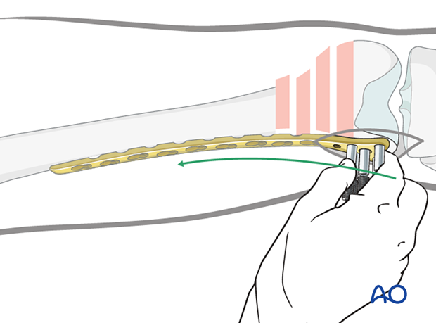
After accurate closed reduction of the metaphyseal fracture, the condylar VA-LCP is ready to be inserted. Slide the condylar VA-LCP into a pre-prepared submuscular tunnel between the vastus lateralis muscle and the periosteum (= epiperiosteal space).
Advance the condylar VA-LCP proximally under the vastus lateralis muscle, ensuring that its proximal end remains in constant contact with the bone. Position the distal end of the plate against the lateral condyle. To identify the correct position, move the condylar VA-LCP proximally and then back distally until the plate perfectly fits the lateral condylar surface.
Proper position check - Position on the distal femur
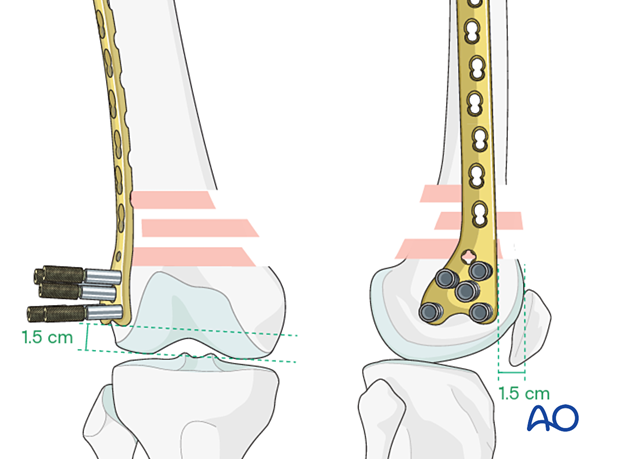
When the plate lies flat on the lateral surface of the condyle, it has been positioned correctly on the distal femoral articular block.
- The anterior edge of the head of the Condylar VA-LCP is usually 1.0-1.5 cm from the anterior aspect of the medial femoral condyle.
- The distal edge of the Condylar VA-LCP is usually 1.5 cm from the distal condylar articular surface.
Readjust plate position if necessary.
Insertion of first guide wire
Insert a guide wire through the central hole of the plate and check it's position by image intensifier in all planes.
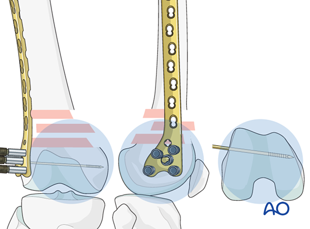
Verification of allignment
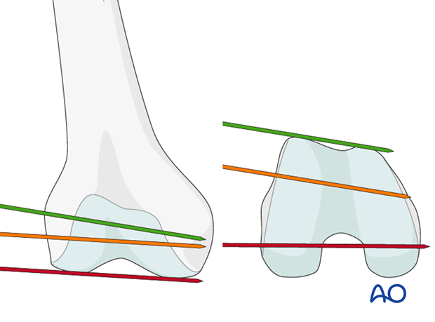
Determine the correct position for the central screw of the LCP with the help of guide wires around the joint. Under image intensifier control, pass one guidewire lateral to medial along the tibio-femoral joint line (red). Pass a second guidewire over the anterior the surface of the knee to indicate the plane of the patellofemoral condyles.
The ideal position of the central screw of the LCP is shown by the yellow wire. Note that it is inserted parallel to both the red wire in the frontal plane and is parallel to the green line on the end-on view on the femur. This latter orientation ensures that the plate comes to lie flush with the lateral cortex.
Insertion of second quide wire
Insert a second guide wire in one of the 5.0 mm screw holes to provisionally fix the plate to the femoral articular block.
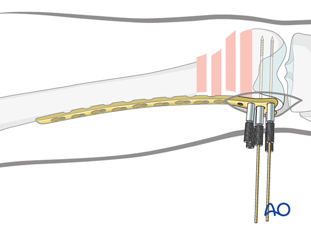
Verification of second guide wire trajectory
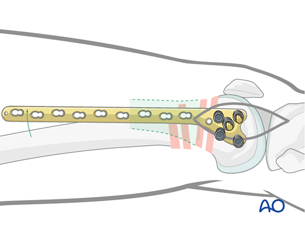
Confirm distal plate placement, using visual examination and an image intensifier. Ensure that the guide wires inserted through any of the four most distal 5.0 mm screw holes in the head of the plate are parallel to the tibio-femoral joint plane.
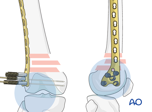
Check that the plate is properly orientated on the lateral femoral condyle. Because the shaft of the femur is frequently out of alignment with the distal femoral articular block, proper plate placement can be determined by matching the shape of the distal portion of the plate to that of the condyle. The position of the plate on the distal femoral articular block at this point will determine the final flexion/extension reduction. This reduction is important because this fracture usually falls into extension; this must be prevented.
7. Preliminary plate fixation
K-wire insertion in proximal fragment
Make an incision over the proximal two holes of the plate. Deepen this incision through the iliotibial band and the vastus lateralis muscle belly (not using the internervous intermuscular plane) to allow palpation of the proximal aspect of the plate on the lateral aspect of the femur.
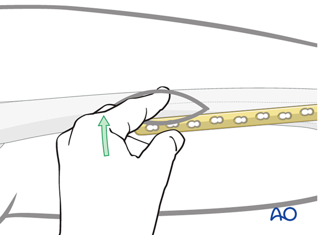
Insert a K-wire through one of the proximal plate holes into the lateral cortex in order to hold the plate loosely on the lateral aspect of the femur.
Screw length measurement in distal femoral articular block
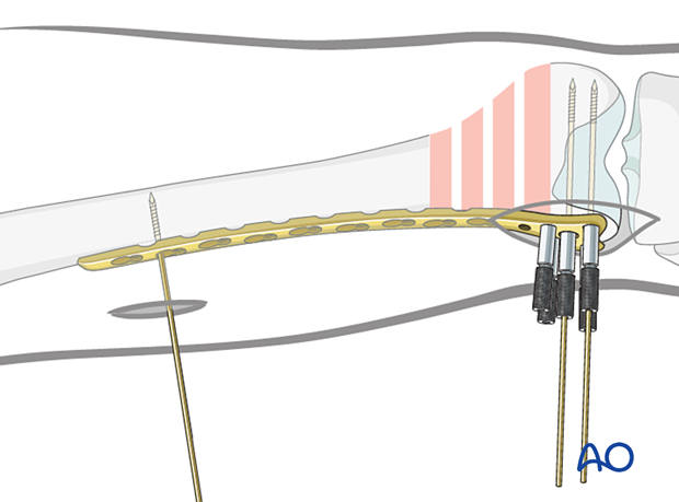
Advance the guide wires until they reach the medial cortex of the femoral condyle, but they should not penetrate the cortex.
Use the measuring device to indirectly measure the lengths of the screws using the guide wires.
For proper measurement, the measuring device must contact the end of the threaded wire guide. This will place the tip of the screw at the tip of the guide wire.
Distal screw insertion
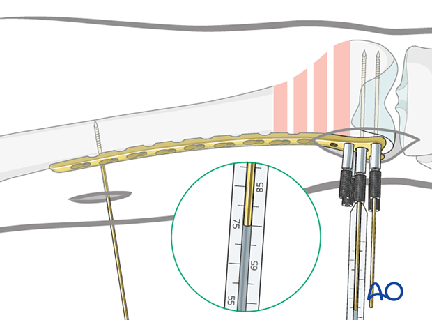
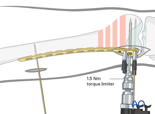
The central wire guide is removed from the plate head and the central screw (7.3 mm) is inserted over the guide wire, using the torque-limiting power screwdriver.
Self-tapping screws are used.
Inserting only one screw at this point allows correction of small deformities in the sagittal plane (on the lateral x-ray).
After confirming that the plate is in the correct position on the distal femur, when viewed on a lateral x-ray, the additional screws (5.0 mm) should be inserted into the distal femoral articular block.
Regular locking screws or variable angle screws may be chosen based on any previously inserted lag screws.
8. Intraoperative radiological assessment
Establishment of rotation
A simple “rule-of-thumb” is that the foot should be externally rotated 10° after fixation of the supracondylar fracture. If the rotation is correct, the anterior superior iliac spine, the center of the patella and the second toe should be in line. Additionally, and more precisely, the rotation can be assessed using the image intensifier with the lesser-trochanter sign or the Bouvier cord method (see above).

Assessment of rotation
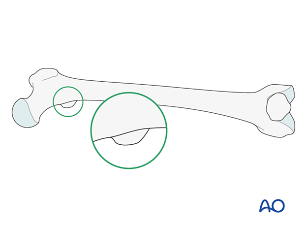
Compare the profile of the lesser trochanter with that of the contralateral leg (lesser trochanter shape sign), holding the leg so that the patella faces anteriorly on both sides.
Before positioning the patient, store the profile of the lesser trochanter of the intact opposite leg (patella facing anteriorly) in the image intensifier.
The illustration shows the lesser trochanteric profile of the intact opposite side.
Malrotation
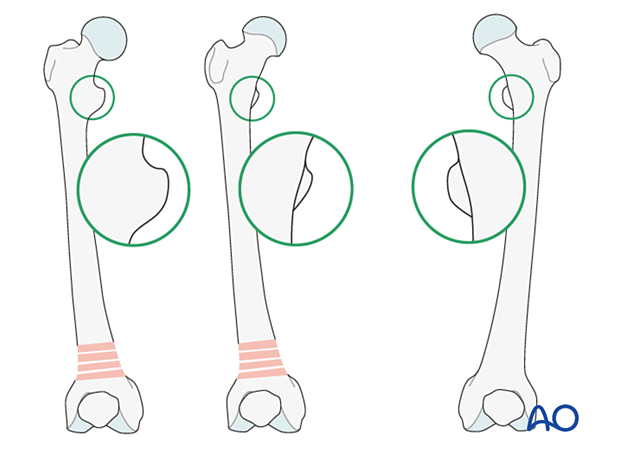
In cases of malrotation, the lesser trochanter is of a different profile when compared to that of the contralateral leg.
Take care to assess rotation with the patella facing directly anteriorly.
Matching of the lesser trochanter shape
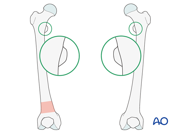
After securing the plate to the distal femur, correct any malrotation by rotating the distal femur. Ensure that the profiles of the lesser trochanters are matched.
Sagittal plane alignment
Check the reduction on the lateral image intensifier image before the second proximal K-wire is placed. A common deformity is that the distal end of the proximal segment is projecting anteriorly and must be pushed down into appropriate reduction. This is often accomplished by pushing with a mallet.
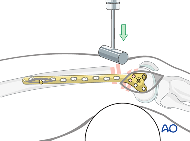
When the correct alignment is achieved, a second K-wire is inserted to fix the sagittal plane alignment.
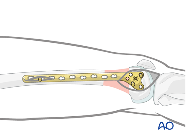
9. Fixation of plate to proximal fragment
First proximal screw insertion (bridging technique)
After ensuring that the appropriate length and rotation have been obtained, insert a standard bicortical screw into the proximal segment. Generally, use the most proximal plate hole through the previously made approach to the femur.
Remove the previously inserted K-wire. Palpate and maintain the position of the plate on the lateral aspect of the femur.
Drill, measure screw length and insert the chosen self-tapping screw in neutral mode through both cortices.
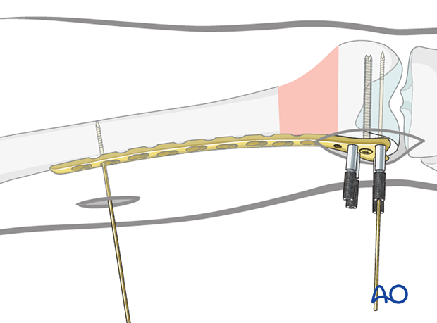
Insertion of further screws in the proximal segment
Under image intensifier guidance (as necessary) insert the chosen self-tapping 4.5 mm screws. (Their lengths can be estimated, but must be checked, and are generally 38 to 42 mm.)
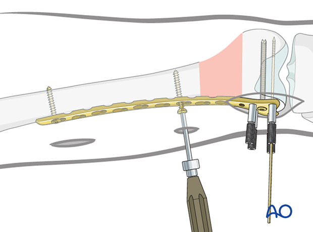
10. Completed osteosynthesis
Additional screw placement
Distal segmentInsert additional screws for a minimum total of 4 screws distally. These may be locking or variable angle locking head screws.
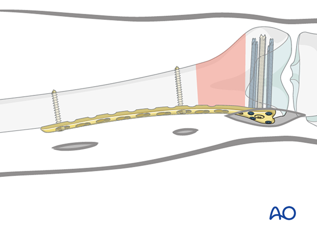
Insert additional screws for a minimum total of 4 proximally, either standard bicortical screws inserted in neutral mode (as illustrated), or locking-head screws may be used. Locking head screws are only useful in osteoporotic bone.
A standard screw is inserted after drilling with a 3.2 mm drill bit.
A 5.0 mm locking-head screw is inserted after drilling with a 4.3 mm drill bit through the threaded drill sleeve.
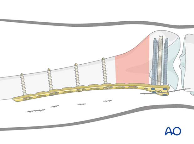
Final check of fracture reduction and fixation
Gently move the knee through a full range of motion. Carry out a clinical assessment of the rotational profile. Finally, perform a radiographic assessment of the frontal-plane alignment (varus/valgus) and sagittal-plane alignment (extension/flexion).
Examine the knee for any ligamentous instability.
Double plating
If the construct is deemed insufficient to guarantee stability, a second plate may be applied medially.
For more details on the application of a medial plate, please see the procedure on double plating.
11. Aftercare
Impediments to the restoration of full knee function after distal femoral fracture are fibrosis and adhesion of injured soft tissues around the metaphyseal fracture zone, joint capsular scarring, intra-articular adhesions, and muscle weakness.
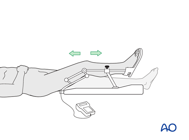
Early range of motion helps restore movement in the early postoperative phase. With stable fracture fixation, the surgeon and the physical therapy staff will design an individual program of progressive rehabilitation for each patient.
The regimens suggested here are for guidance only and not to be regarded as prescriptive.
Functional treatment
Unless there are other injuries or complications, knee mobilization may be started immediately postoperatively. Both active and passive motion of the knee and hip can be initiated immediately postoperatively. Emphasis should be placed on progressive quadriceps strengthening and straight leg raises. Static cycling without load, as well as firm passive range of motion exercises of the knee, allow the patient to regain optimal range of motion.
Weight bearing
Touch-down weight-bearing (10-15 kg) may be performed immediately with crutches, or a walker. This will be continued for 6-10 weeks postoperatively. This is mostly to protect the articular component of the injury, rather than the shaft injury. Touch-down weight-bearing progresses to full weight-bearing gradually, over a period of 2 to 3 weeks (beginning at 6–10 weeks postoperatively). Ideally, patients are fully weight-bearing, without devices (e.g., cane) by 12 weeks.
Follow-up
Wound healing should be assessed at two to three weeks postoperatively. Subsequently 6-week, 12-week, 6-month, and 12-month follow-ups are usually made. Serial x-rays allow the surgeon to assess the healing of the fracture.
Implant removal
Implant removal is not essential but should be discussed with the patient if there are implant-related symptoms after consolidated fracture healing.
Thrombo-embolic prophylaxis
Thrombo-prophylaxis should be given according to local treatment guidelines.
