Cancellous lag screw insertion
1. Principles
The function of the lag screw is to compress one piece of bone against another. This improves the stability of a reduction, so it is commonly used to achieve absolute stability, leading to direct bone healing, as opposed to healing with callus.
2. Screws
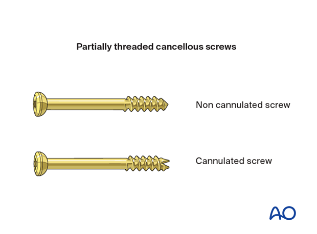
Various screw types are available, and details of the lag screw technique will depend on the type of screw used.
3. Screw axis
Generally, the axis of the screw should be as perpendicular as possible to the plane of the fracture.
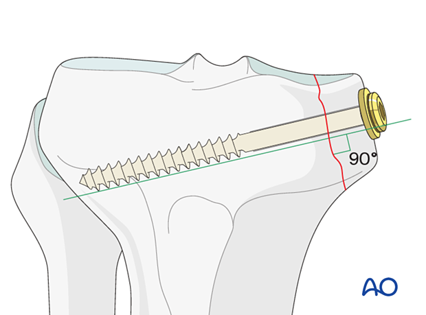
Metaphyseal fractures occur close to joints. A large fragment may include a significant portion of the joint surface. If this is loaded, there will be a tendency for the fragment to displace.
To counter this shearing effect, the orientation of a lag screw may be adjusted so that it is not quite perpendicular to the fracture plane but lies more perpendicular to the long axis of the bone.
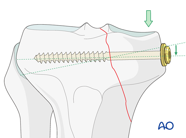
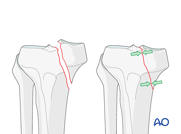
The left panel shows the axis of the screw as perpendicular as possible to the plane of the fracture. In the right panel the screw is far from perpendicular, and as it is tightened there will be a shearing force, which risks displacing the fracture.
- Compressive forces are indicated by arrows
- The animation on the right shows one possible failure mechanism
The compressive effect occurs between the head of the screw and the threads at the far end of the screw as the screw is tightened.
To achieve this effect the screw must be able to move in the near hole without the thread obtaining purchase. A screw with an appropriate unthreaded shaft length should be selected.
The cortex tends to be very thin near the ends of the bone, particularly if osteoporosis is present. As the screw is tightened, stresses at the bone are higher and there is a risk that the head will sink into the bone. This can be prevented by using a washer (left panel).
4. Reduction and temporary fixation
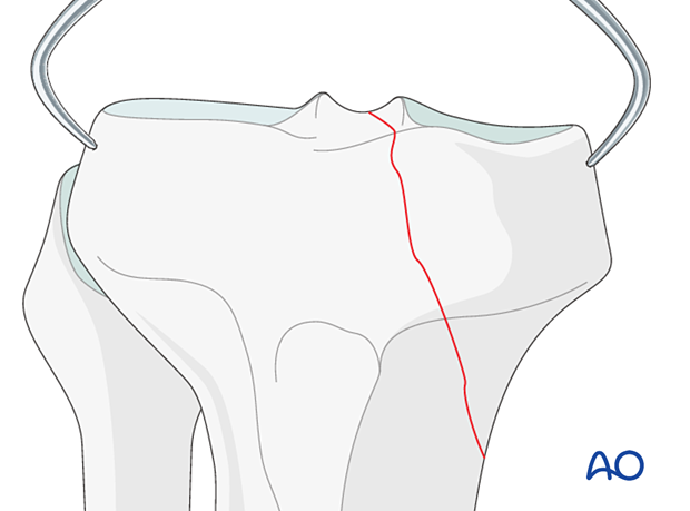
The fracture is reduced, and the reduction temporarily held, eg, with reduction forceps.
5. Pilot hole
The pilot hole is drilled perpendicular to the fracture plane, with a diameter corresponding to the core diameter of the screw.
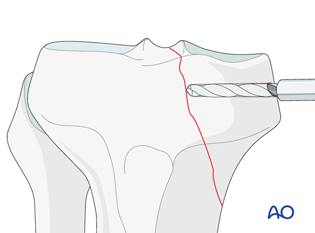
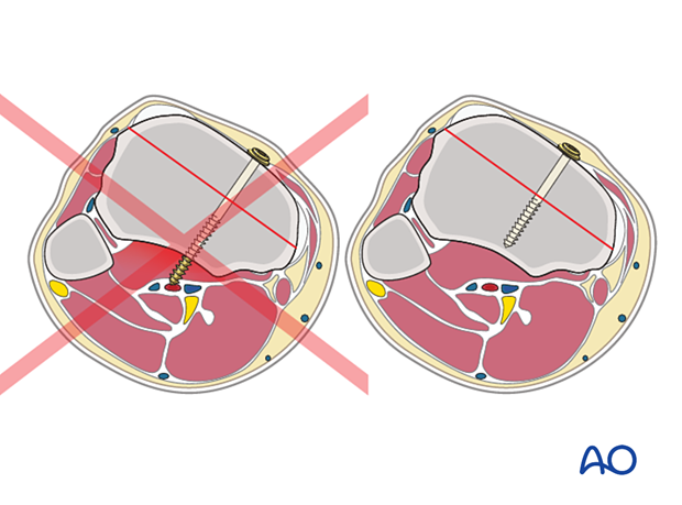
As there is minimal cortical bone in the metaphyseal region, and the threads of the screw are holding in the cancellous bone, there is no need for the screw to penetrate the far side of the bone.
In addition, there are often important soft tissue structures adjacent to the bone in the metaphyseal region, which may be damaged or irritated by a protruding screw.
6. Screw length
Measure the depth of the hole to determine the screw length, taking into account the thickness of the washer, if one is to be used.
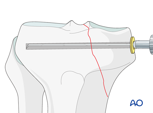
7. Screw selection
A partially threaded screw is selected. The threaded segment should only hold in the far fragment of cancellous bone. None of the threaded segment should remain in the near fragment of bone. Correct screw selection is shown in the left panel.
If threads are present in the near fracture fragment, compressive forces cannot be generated (right panel).
8. Screw insertion
The torque must not exceed the holding power of the threaded segment of the screw in the cancellous bone. Therefore, care must be taken to avoid maximal torque. When using a screwdriver, the surgeon may choose to use a tripod finger grip instead of a power palmar grip.
9. Lag screw with neutralization device
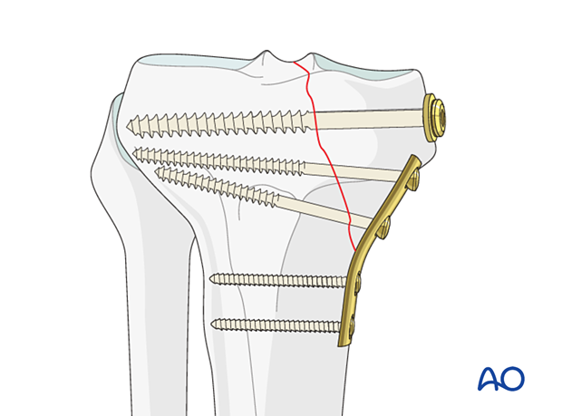
If the hold of lag screws alone is inadequate, a neutralization or buttressing device such as a plate or an external fixator should be used to provide additional stabilization.
The plane of the fracture dictates the position and direction of the lag screw. Anatomic considerations will influence the optimal positioning of the plate.
If the plate position and lag screw insertion site are aligned, the lag screw may be inserted through the plate.
The plate should be contoured and positioned appropriately. Then, with the fracture and the plate fixed to bone distal to the fracture, the lag screw/s is/are inserted through the plate.
If the location of the fracture plane makes it necessary to insert the lag screw from a position where it would be awkward to apply a plate, the lag screw can be inserted outside the plate.
More information about the use of Buttress (antiglide) plates is provided here.
