MIO - Angular stable plate (LISS)
1. Principles
Internal fixators
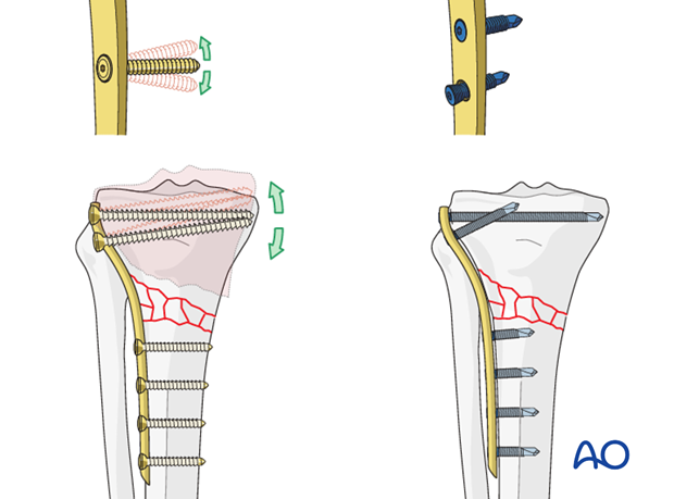
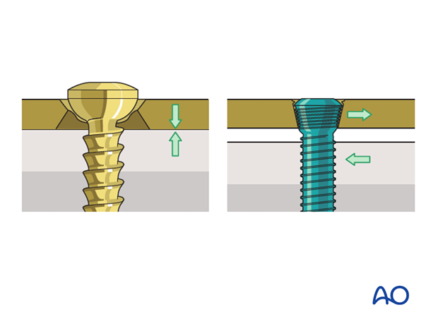
The new generation of plates act as “internal fixators”. This is achieved by locking the screw heads into the plate via a thread in the screw head. In contrast to conventional plates, these implants fix the fractured fragments in the determined position without the screws loosening, which could lead to secondary displacement.
In case of healthy bone structure, monocortical angular stable screws are applied. As an alternative, bicortical angular stable screws can be chosen, especially in case of osteoporosis, or a combination of monocortical and bicortical screws can be chosen.
No direct bone to plate contact
A second advantage of the new angular stable plates is that they do not require firm contact and pressure between plate and bone surface for stability. Even when placed distant to the bone, their fixation strength is superior to conventional plates. This means that blood flow in the periosteum is less compromised than in open conventional procedures.
Load bearing
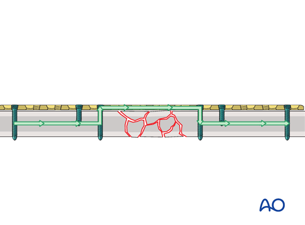
The load from one fracture fragment to the other is completely borne by the implant.
Anatomy
The medial plateau is the larger of the two articular surfaces and is concave in both transverse planes. The lateral plateau is smaller and convex and lies slightly higher than the medial joint surface, which helps in identifying it on the lateral x-ray.
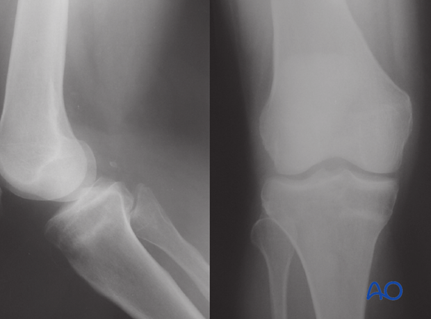
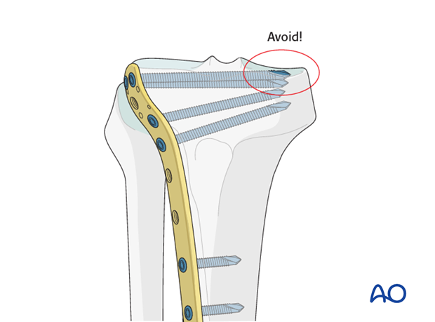
When inserting screws from lateral to medial this fact must be taken into consideration in order to avoid penetrating the concave medial joint surface.
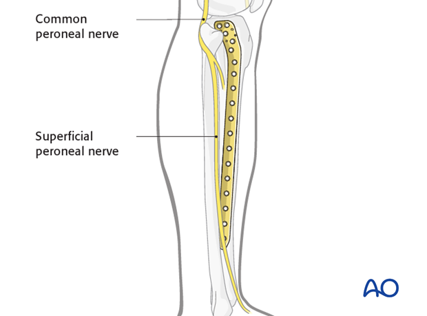
Superficial peroneal nerve
A slightly elongated distal incision is useful both to check plate location and avoid damage to the superficial peroneal nerve. The nerve crosses the tibia in the proximity of the distal part of the 13-hole plate (be careful with short stature patient where this can happen even with a nine hole plate).
Compartment syndrome
Monitor the neurovascular status of the limb carefully not to miss a compartment syndrome.
2. Preoperative planning
Anatomical reduction first
Anatomical reduction of the articular surface is mandatory before fixation of the metaphyseal fracture fragment.
Not all complete articular fractures can be perfectly reduced through a medial and/or a lateral approach. Sometimes fractures with a flexion injury mechanism need to be approached posteriorly as well.
Plate length
Generally speaking, the plates for the bridging technique should be rather long in order to distribute the forces, as well as to provide relative stability
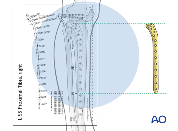
The preoperative x-ray planning template is useful in determining the length of the LISS plate and the position of the screws.
Number of screws
In case of healthy bone structure, five well placed monocortical angular stable screws are applied to secure the LISS to the tibial shaft. As an alternative, three bicortical angular stable screws can be chosen, and are recommended in patients with osteoporosis.
If LISS with “combi” holes is used, regular screws opposed to angular stable screws can be used in good bone stock. In this case four regular bicortical screws were used in the distal fracture fragment.
See also
Gautier E, Sommer C (2003) Guidelines for the clinical application of the LCP. Injury 34(Suppl 2):B63-76. Review
3. Patient preparation
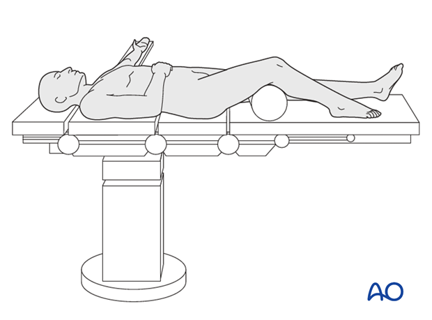
This procedure is normally performed with the patient in a supine position.
4. Approaches
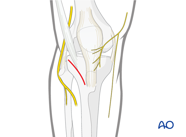
Approach for minimally invasive osteosynthesis (MIO)
For this procedure a MIO approach is used.
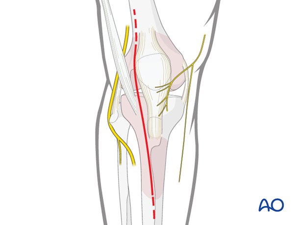
Anterolateral approach
For a more open reduction an anterolateral approach is used.
5. Reduction and fixation of the articular block
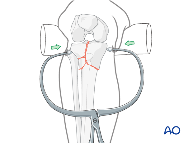
Reduction of the articular block using clamps
Indirect reduction may be achieved by external manipulation of the fracture fragment with clamps. In cases where adequate closed reduction is not achieved, the joint should be opened to allow anatomical reduction.
Control reduction either arthroscopically or under image intensification.
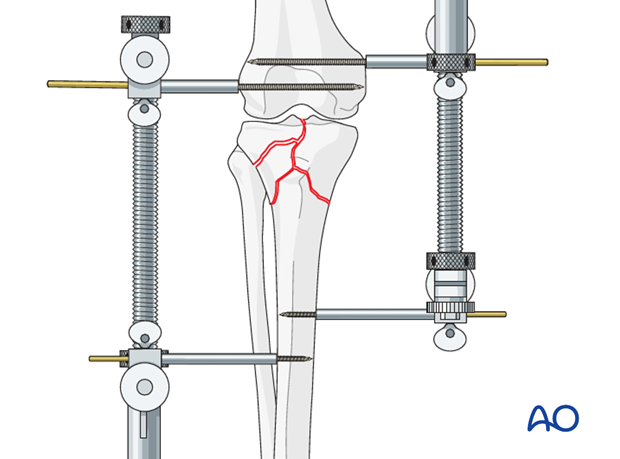
Alternative: single or double distractor
Fracture reduction techniques in the proximal tibia rely on the concept of indirect reduction to realign the fracture fragments where one relies on ligamentotaxis, that is the attachment of soft-tissue hinges such as ligaments and muscle. These techniques require the use of one or two large distractors bridging the slightly flexed knee. Ligamentotaxis can reduce a considerable portion of the fracture, primarily large condylar fragments, as well as realign the diaphyseal-metaphyseal shaft extension of the fracture.
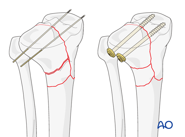
Lag screw principle
Anatomical reduction of the articular surface is mandatory. Use K-wires for temporary and lag screws for definite stable fixation. Remember to make allowances for the position of the plate.
Click here for a detailed description of the lag screw technique.
6. Reduction of the metaphyseal fracture component
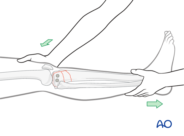
Manual closed reduction
Reduce the metaphyseal component by pulling on the leg and restore axial alignment, length, and rotation.
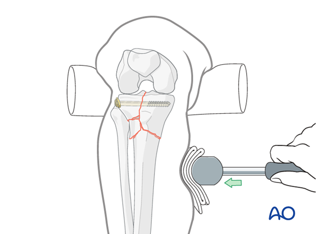
Reduction by use of a mallet
In some cases, reduction may be easier with the help of soft instruments to apply direct forces to the fracture site (eg, hammer with a towel). Care must be taken not to produce additional soft-tissue damage.
Alternative: use or external distractor
If you have used a single or double distractor for reduction of the articular surface, then keep it on for the metaphyseal component.
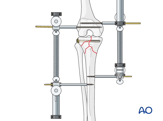
7. Preliminary fixation
LISS insertion
Once the LISS has been assembled and fixed to the guide handle with the fixation bolt and stabilization sleeve inserted through the hole C of the guide you are ready to insert the internal fixator onto the bone.
Insert the assembled internal fixator between the anterior tibial muscle and the periosteum in the epiperiosteal space. The LISS plate is slid in the distal direction, with its distal end in constant contact with the bone. The proximal end of the plate is positioned against the lateral condyle. The correct position of the LISS on the condyle is checked carefully.
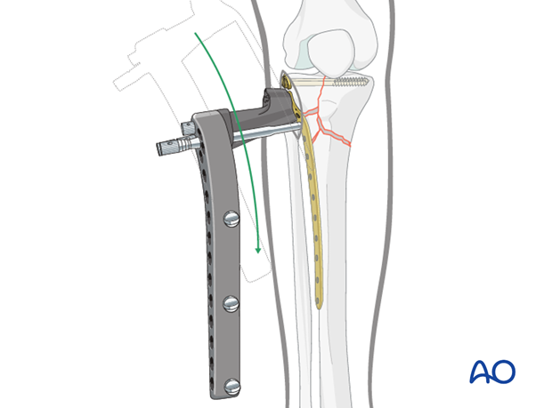
Building a frame - make a small incision over the most distal hole
Once the LISS is properly aligned with the bone, the drill sleeve is removed from hole labeled “C”. Next insert the drill sleeve and trocar though the most distal hole of the drill guide depending on the length of plate you have chosen (5,9, or 13). Before you can reach the plate with the drill sleeve and trocar you must must make a stab incision. If you are using a long plate (9 in a short individual or 13 in a normal individual) dissect down to the plate to avoid injuring the superficial peroneal nerve. Once all is secure insert the drill sleeve and trocar and secure the drill sleeve to the guide handle. Remove the trocar and replace it with the fixation bolt which you thread into the plate. This completes the building of the frame.
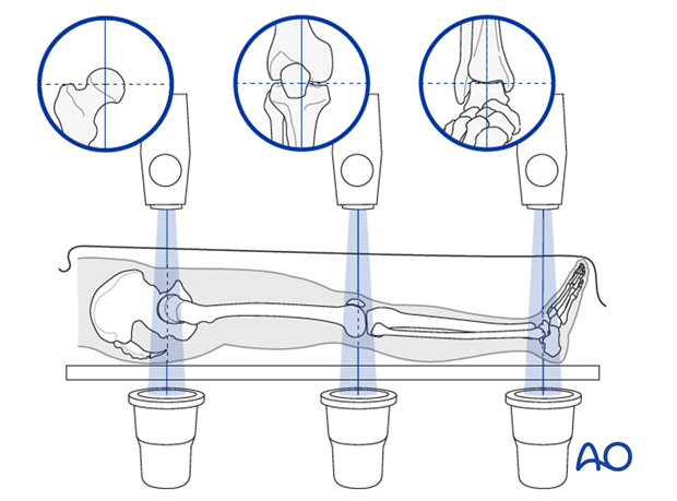
You must check the position of the LISS with the image intensifier in both the AP and lateral position.
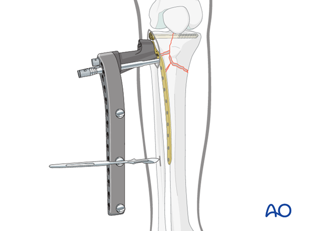
Be aware of the superficial peroneal nerve
If a 13-hole LISS plate is being used or a 9 hole in a short stature individual, careful soft-tissue dissection has to be carried out down to the plate before inserting the trocar and drill sleeve, in order to visualize the superficial peroneal nerve. Once all is secure the position of the drill sleeve is held securely by tightening the fixation screw on the insertion guide. The trocar is then replaced with the stabilization bolt. The stabilization bolt is threaded into the LISS plate to close the frame.
It should be noted that once the bolt has been inserted, it becomes difficult to change the position of the plate–guide assembly, due to the soft tissues around the stabilization bolt.
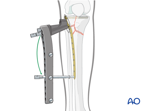
Illustration showing the relationship of the superficial peroneal nerve and the plate.

Preliminary fixation of the LISS
For preliminary fixation of the internal fixator, 2.0 mm K-wires are inserted through the most proximal K-wire hole on the insertion guide (guided only through the aluminum foot part of the insertion guide) and through the stabilization bolt in the most distal hole of the LISS.
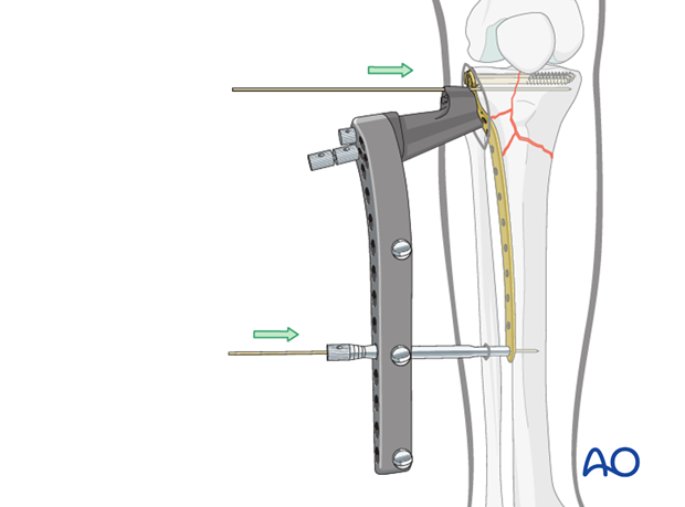
Pitfall: check proper plate alignment of the LISS on the lateral side of the proximal tibia
Be aware of the position of the LISS before you insert the proximal K-wire. The correct position for the LISS is on the lateral aspect of the proximal tibia just anterior to the fibula.
If the plate is positioned too anteriorly the fixation screws may endanger the popliteal artery.
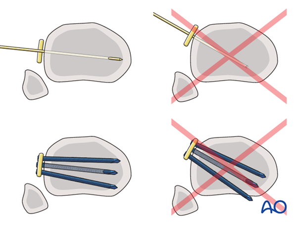
Pitfall: check proper plate alignment of the LISS on the lateral tibial shaft in both the AP and lateral projection
Before fixing the LISS to the bone with the screws in the shaft area, check if they all are in a central position in the lateral cortex. In the event of an eccentric position, there is substantial risk of implant failure with loss of fixation due to the fact that eccentrically inserted screws have a markedly reduced fixation strength. This applies especially to monocortical screws.
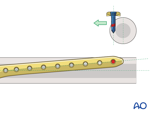
Image showing proper screw position.
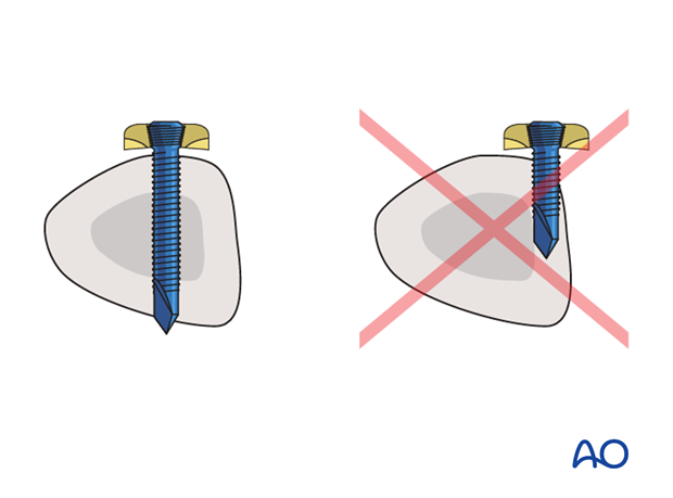
8. Screw placement
General considerations
Screw placement depends on the type of fracture. The positions of the locking head screws should be chosen in accordance with the established biomechanical principles for internal fixation. The locking head screws should be inserted remote from the fracture gap in the main diaphyseal fragment. Three to four plate holes in the region of the fracture zone should remain free of screws to ensure sufficient elasticity of the construct.
It should be noted that once the initial locking head screws have been inserted into each main fragment, length and rotation are fixed. Antecurvatum and recurvatum deformities can still be adjusted within narrow limits. For this reason, it is recommended to start by inserting the first locking head screw in the proximal fragment.
If a screw has to be removed and reinserted, the hand torque limiting screwdriver should be used and not the power tool.
Measuring of screw length for proximal fragment
Use the measuring device with a 2.0 mm K-wire of 280 mm length, placed through the centering sleeve in the drill sleeve. This will allow you to determine the appropriate screw length. Using image intensification, the K-wire is pushed to the desired depth, leaving at least 5 mm between the tip of the K-wire and the medial cortex. The screw length is measured over the K-wire using the measuring device for K-wires while the guide sleeve in place. The length is rounded down to the nearest screw length. This will ensure that the tip of the screw will not protrude through the medial cortex.
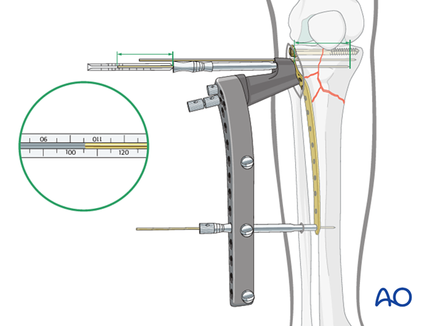
9. Fixation
Insertion of locking head screw in the articular block
To improve visualization of the condyle, the drill sleeves for the two most proximal holes are guided through the aluminum foot part of the insertion guide only. To prevent rotation of the drill sleeve, it is therefore necessary to hold it with two fingers during insertion or removal of the K-wire, as well as during insertion or removal of the two most proximal screws.
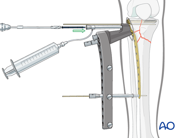
Pearl: fine tuning of the reduction
The shaft fragment has a tendency to drift away from the plate. To fine tune the reduction or the approximation of the LISS to the bone, the Whirlybird may be used. It has a sliding nut on its proximal end which can be tightened against the insertion guide, thus approximating or docking the bone to the LISS.
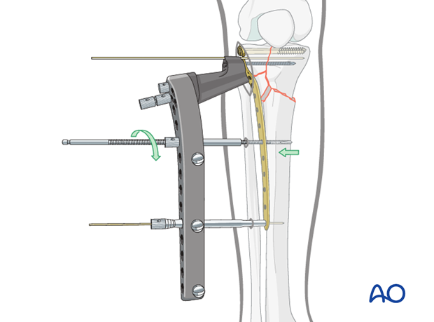
Insertion of the first distal locking head screw
The image intensifier should be oriented obliquely to allow accurate visualization of the point at which the K-wire exits anteromedially or posteromedially.
26 mm or 18 mm locking head screw should be used in the shaft region.
Initially, a stab incision is made and the trocar is inserted through the drill sleeve.
Battery-driven or compressed-air tools are used to insert the self-drilling, self-tapping locking head screw, as only these tools provide the required drill speed.
It is also important to cool the locking head screws with saline solution through the drill sleeve during the drilling procedure, to prevent thermal necrosis. The insertion sleeves have a side nipple to allow irrigation. Use standard tubing and syringes with saline solution.
Both the screwdriver shaft and the torque-limiting screwdriver are equipped with a self-holding mechanism. Slight pressure should be used to ensure that the screwdriver shaft penetrates the socket of the screw head on pick-up.
In case the whirlybird technique was used, the first distal locking head screw should be inserted next to it.
Note: torque-limiting screwdriver
For the final tightening the torque-limiting screwdriver has to be used. The torque-limiting screwdriver is used for final tightening until clicking occurs at 4 Nm.
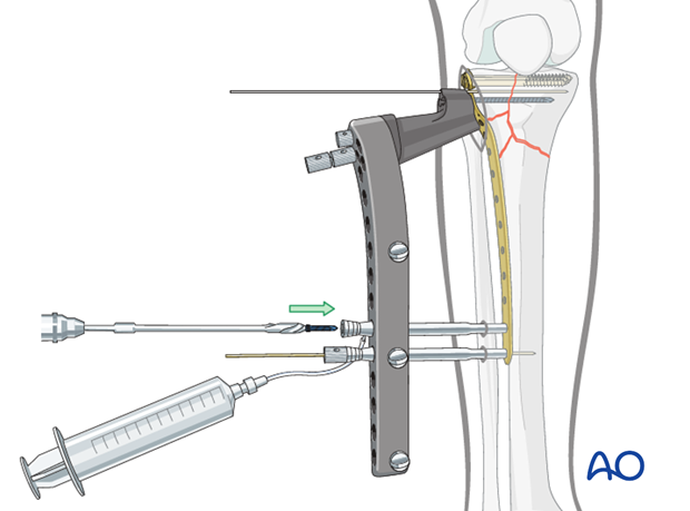
Intraoperative assessment of fracture reduction
Length, alignment, and rotation should be checked clinically. The knee is taken through a full gentle range of motion to ensure appropriate fracture fixation. Fracture reduction and fracture fixation are then assessed using AP, lateral, and oblique x-rays. Specific questions to be answered in this assessment include:
- Is there any sagittal plane deformity?
- How satisfactory is the valgus/varus alignment?
The cable method is recommended for checking the alignment of the limb.
- Length, alignment, and rotation should also be checked clinically.
- How satisfactory is the placement of the LISS fixator on the midlateral aspect of the tibia?
- How satisfactory is the placement of the LISS fixator on the lateral aspect of the tibial condyle.
- If in doubt, take an AP and lateral X-ray from the knee to the ankle.
Additional screw placement
According to preoperative planning additional screws are inserted into the proximal and distal fracture fragment with the both K-wires still in place.

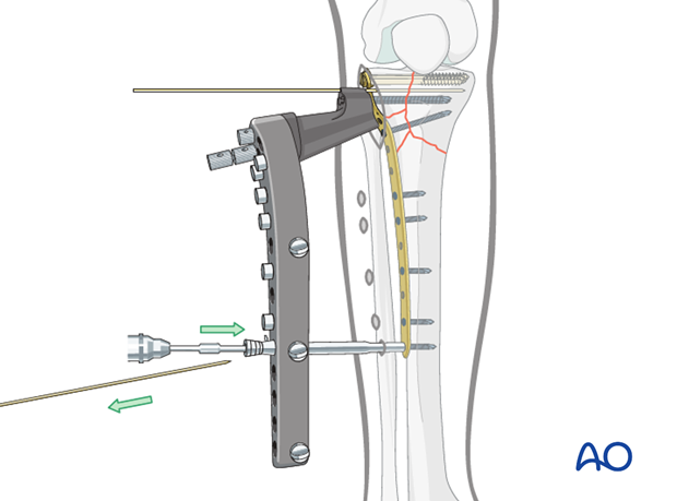
Removal of the K-wire and insertion of a locking head screw in the most distal plate hole
The most distal locking head screw on the fixator should be inserted last, just before removal of the insertion guide, in order to ensure the stability of the construct. The stabilization bolt is then removed and the screw is inserted through the drill sleeve.
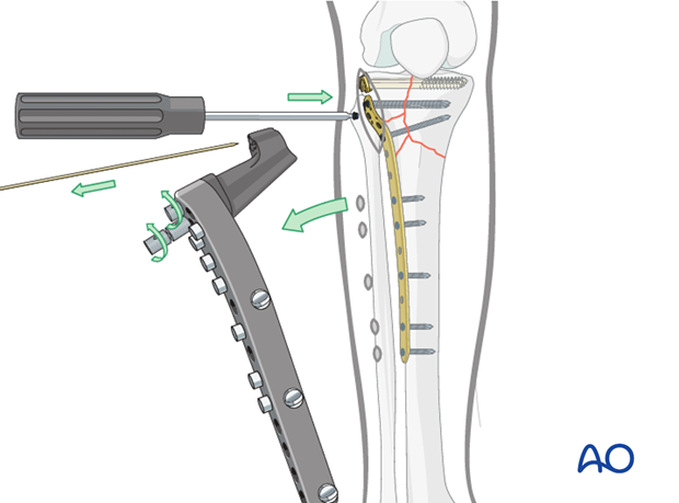
Removal of the insertion guide, and placement of the “A” proximal tibial locking head screw
The insertion guide is then disconnected from the fixator. Insert a locking head screw or a screw hole inserter into the “A” proximal tibial screw position.
Intraoperative assessment of fracture stability after fixation
Specific questions to be answered in this assessment include:
- Are all of the screws really placed monocortically into the bone, or are some positioned too far anteriorly or posteriorly?
- Are any of the locking head screws in the popliteal fossa and endangering the popliteal artery? (Although rare, this can occur with excessive anterior positioning of the fixator or malreduction where the shaft is internally rotated with respect to the proximal fragment.) This can be assessed intraoperatively and by image intensification.
- It should be checked that self-drilling, self-tapping locking head screws have not perforated the medial cortex.
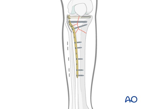
Wound closure
All wounds are irrigated extensively. The reinsertion of the anterior tibialis muscle is performed. Then, the skin is closed in a routine manner.
10. Aftercare
Compartment syndrome and nerve injury
Close monitoring of the tibial compartments should be carried out especially during the first 48 hours after surgery to rule out compartment syndrome.
The neurovascular status of the extremity must be carefully monitored. Impaired blood supply or developing neurological loss must be investigated as an emergency and dealt with expediently.
Functional treatment
Unless there are other injuries or complications, mobilization may be performed on post OP day 1. Continuous passive motion (CPM) splints are very helpful in the early phase of rehabilitation. Static quadriceps exercises with passive range of motion of the knee should be encouraged. Afterwards special emphasis should be given to active knee and ankle movement.
Following any injury, and also after surgery, the neurovascular status of the extremity must be carefully monitored. Impaired blood supply or developing neurological loss must be investigated as an emergency and dealt with expediently. The goal of early active and passive range of motion is to achieve as full range of motion as possible within the first 4 - 6 weeks. Optimal stability should be achieved at the time of surgery, in order to allow early range of motion exercises.
Weight bearing
No weight bearing in the treatment of articular fractures for a minimum of 10 – 12 weeks.
Follow up
Wound healing should be assessed on a short term basis within the first two weeks. Subsequently a 6 and 12 week follow-up is usually performed. If a delayed union is recognized, further surgical care will be necessary and should be carried out as soon as possible.
Implant removal
Implant removal is not mandatory and should be discussed with the patient.
