Lag screw technique
1. Principles
Lag-screw technique
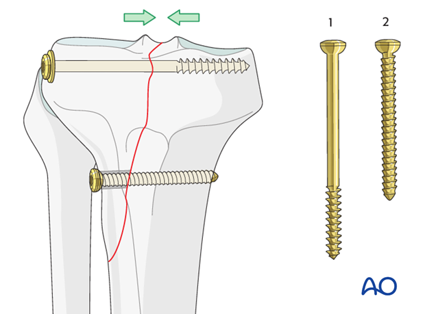
Lag screws / the lag technique compresses the fracture fragments together. There are two screw types by which to achieve this. The cancellous bone screw and the cortical screw through a gliding hole. In the proximal tibia most often cancellous bone screws are used due to the absence of real cortical bone. Nevertheless, there are some indications for cortical lag screws.
1) Cancellous bone screw
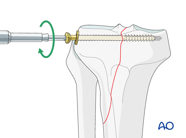
Cancellous bone screws have threads only on the terminal end of the screw. Therefore, when inserted across a fracture, the threads of the tip of the screw engages in the cancellous bone of the metaphyseal area, causing compression of the fracture fragments upon tightening. Because of the weakness of the cortical bone in this area washers are used to prevent sinking of the screw head into the bone.
2) Cortical screw through gliding hole
The application of cortical screws involves overdrilling the near cortex to the external diameter of the screw. When the screw is inserted, it glides through this hole and the threads only engage the far cortex. As the screw is tightened the head of the screw engages the near cortex and the fracture fragments are compressed together.
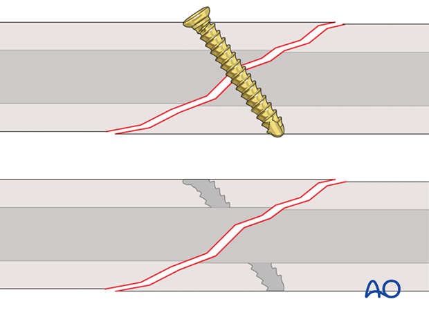
Pitfall: no compression in the fracture when using cortical screws without overdrilling
If the near cortex is not overdrilled, the threads of the screw will engage both near and far cortices preventing compression of the fracture fragments.
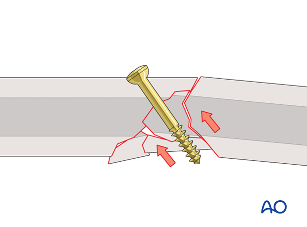
Comminuted fractures
Because lag screws are used to achieve compression and absolute stability, they are usually used for the fixation of simple fractures such as a spiral or oblique fracture but they can also be used under specific circumstances to compress large fracture fragments of a multifragmentary fracture in order to secure added stability.
Perpendicular screw placement
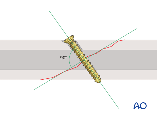
Because lag screws compress the fracture fragments together, they must be placed perpendicular to the plane of the fracture line or the fracture will displace.
In order to reach as much compression in the fracture as possible the lag screw should be positioned perpendicular to the fracture line.
2. Cancellous lag screw application
Drill hole for cancellous screw
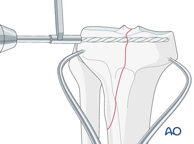
Drill the near cortex of cancellous bone with 3.2 mm drill bit (for a 6.5 mm cancellous screw). Do not perforate the far cortex.
Determine screw length
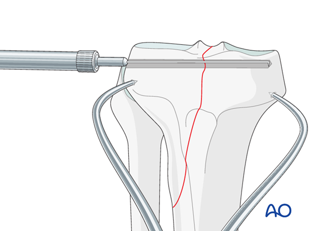
Use a depth gauge to determine the screw length.
Tap
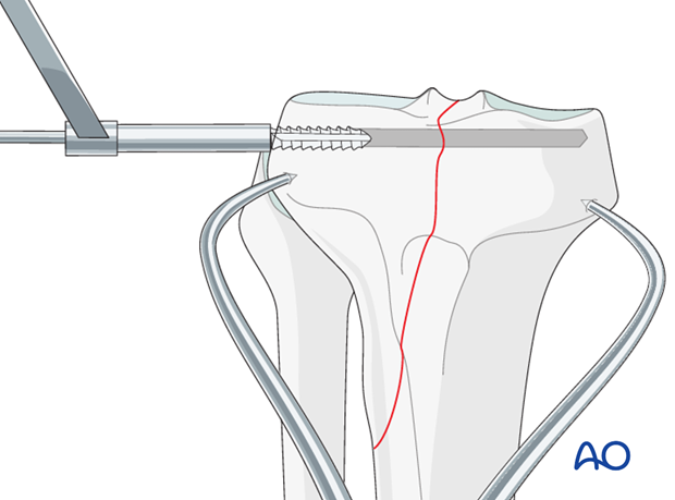
Tap with a 6.5 mm cancellous bone tap only the near cortex. The screw will find its way in the cancellous bone without tapping.
Insert screw
The proper length screw is inserted and tightened. One should observe the near cortex as the screw is tightened to assure that cracking or sinking does not occur from overtightening. Therefore the use of washers is strongly advised in the proximal tibia.
3. Cortical lag screw application
Drill near cortex to external diameter of screw (gliding hole)
The near cortex is perforated using a drill that is the same diameter as the external diameter of the screw.
For example: when using a 4.5 mm cortical screw, the external diameter of the screw is 4.5 mm. The drill that is used to drill the near cortex is therefore 4.5 mm
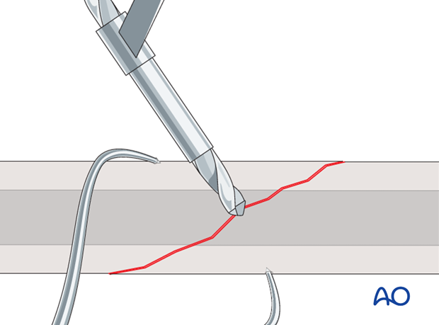
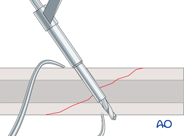
Drill far cortex using “centering” drill guide to inner diameter of screw
A special drill guide is used to drill through the far cortex. This drill guide has an extension on its tip that is the same diameter as the external diameter of the screw. The drill guide fits snugly into the hole previously drilled through the near cortex.
It is imperative that the fracture fragments be properly reduced prior to drilling through the far cortex.
The drill guide centers the drill that will be used to drill the far cortex in order for the two holes to be in line. This drill has the diameter that is similar to the inner diameter or core of the screw. For instance, when using a 4.5 mm screw, a 3.2 mm drill is used to drill the far cortex.
Countersink near cortex
A countersinking tool is used to create a platform in the near cortex.
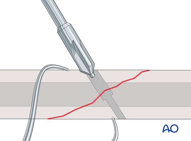
The hole created by the countersinking tool provides a platform for the head of the screw and ensures full contact.
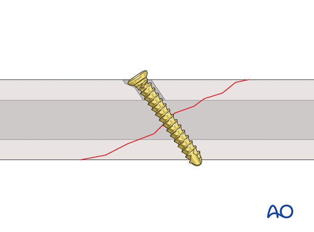
Failure to perform proper countersinking causes an eccentric loading and lessens the degree of compression. In very thin cortex it might also lead to slight displacement of the fragments because of the eccentric force.
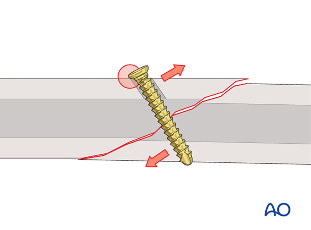
Pitfall: too much countersinking
The medullary canal offers no resistance to the head of the screw. Therefore, it is imperative that countersinking does not remove all of the cortical bone around the circumference of the head of the screw. Otherwise, as the screw is tightened the head of the screw will enter the medullary canal and provide no compression of the fracture fragments.
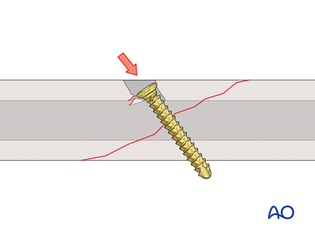
Determine screw length
A depth gauge is used to determine the screw length. It is important that the tip of the screw completely exits the far cortex so that the screw threads engage completely. Therefore, it is always better to select a screw that is slightly longer than slightly shorter than the measurement recorded with the depth gauge.
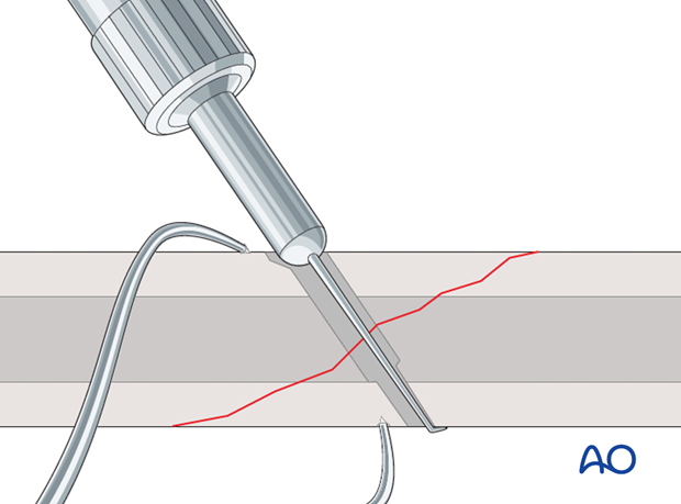
Tap far cortex
If conventional screws are used, tap the far cortex with a 4.5 mm tap. If self-tapping screws are used this step can be omitted.
It is important to push the tap through the gliding hole without turning it in order to avoid a false route of the tap.
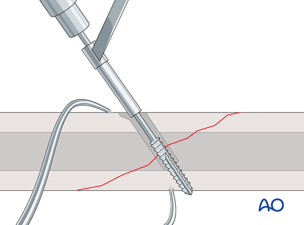
Screw insertion
The screw of appropriate length is inserted and tightened. One should observe the near cortex as the screw is tightened to assure that cracking does not occur from overtightening which might happen in osteoporotic bone.
It is important to push the screw through the gliding hole without turning it in order to avoid starting the screw in a false direction.

