MIO – insertion of condylar locking compression plate (VA-LCP) as neutralization plate
1. Introduction
Anatomy of the distal femur
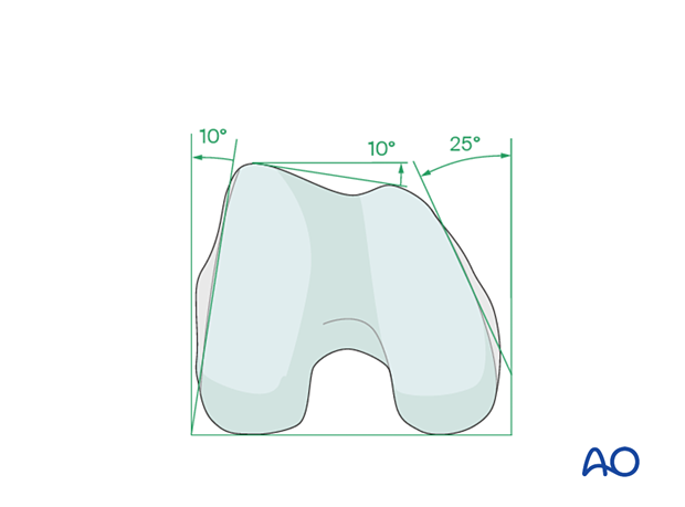
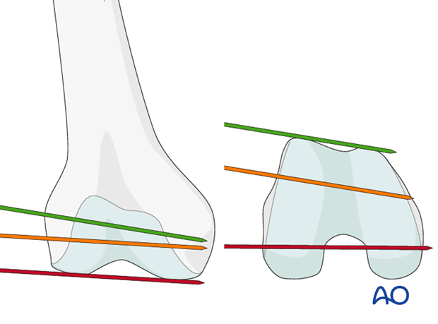
The distal femur has a unique anatomical shape. Seen from an end-on view, the lateral surface has a 10° inclination from the vertical, while the medial surface has a 20–25° slope.
A line is drawn from the anterior aspect of the lateral femoral condyle to the anterior aspect of the medial femoral condyle (patellofemoral inclination) that slopes approximately 10°. These anatomical details are important when inserting screws. In order to avoid joint penetration, these devices should be placed parallel to both the patellofemoral and femorotibial joints planes.
The muscle attachments to the distal femur are responsible for the typical displacement of the distal articular block following a supracondylar fracture, namely shortening with varus and extension deformity. Shortening is due to the pull of the quadriceps and hamstring muscles, while the varus and extension deformity is caused by the unopposed pull of the adductors and gastrocnemius, respectively.
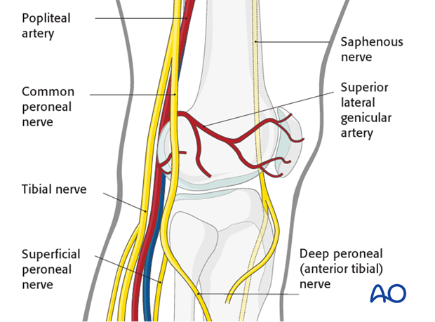
The popliteal vessels, the tibial nerve, and the common peroneal nerve lie near the posterior aspect of the distal femur. Because of this, vascular injuries occur in about 3% and nerve injuries in about 1% of fractures of the distal femur.
There are no significant arteries, veins, or nerves on the lateral side of the knee.
There may be bleeding from the lateral genicular arteries, which will need to be controlled using diathermy.
At the posterior aspect of the knee lie the popliteal artery, nerve, and vein. It must be borne in mind that these structures can be damaged by the injury or can be damaged by the surgeon during the reconstruction.
2. Plate selection
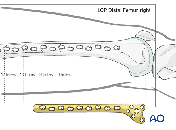
Plate length/number of screws
Whether an absolute or relative stability construct is chosen, sufficient proximal fixation of the plate should be obtained. This typically involves four screws.
The amount of screws placed in the distal end of the plate, should be sufficient to provide appropriate fixation to the distal articular block. A minimum of four screws are typically chosen.
When a relative stability construct is chosen, the plate length should be at least three times as long as the zone of fracture. Nevertheless, most surgeons prefer to apply a plate that spans the entire length of the femur, at least up to the level of the vastus ridge. Bridge plate technique principles should be adhered to where up to 40-50 % of screw holes are filled.
The preoperative x-ray planning template is useful in determining the required length of the condylar VA-LCP and the position of the screws.
3. Patient preparation and approach
Positioning
This procedure may be performed with the patient in one of the following positions:
- Supine position knee flexed 30°
- Supine position knee flexed 90°
- Lateral decubitus (particularly in obese patients)
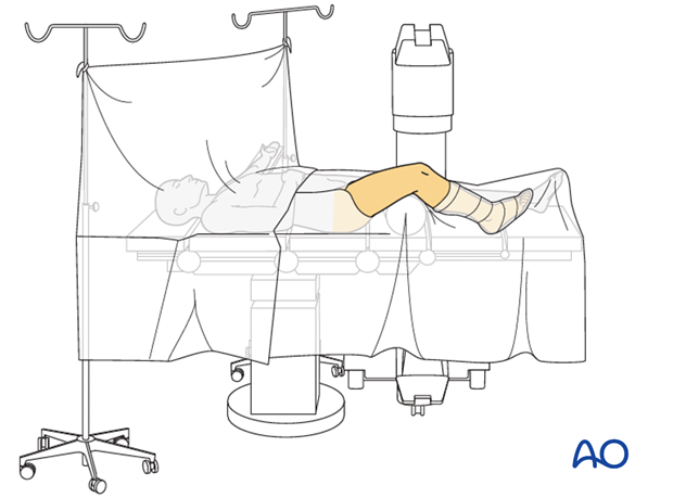
Approach
The MIPO approach for an extra-articular fracture is simple because the articular block is intact. The small opening directly lateral over the end segment should be only as large as to allow the insertion of the implant.
Proximally small incisions on the side of the thigh laterally are used, but only enough to allow for the insertion of individual screws.
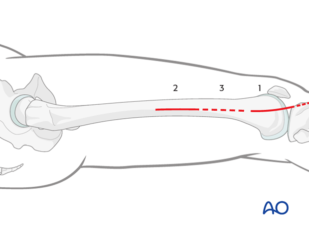
Approach
The MIPO approach for complete articular fractures is more complex because the articular block is fractured. Usually, a lateral parapatellar incision allows access to the end segment. In some situations, medial parapatellar or modified parapatellar approach may be used to obtain reduction and insert screws.
Once multiple lag screws are applied (being careful to keep these screws away from the anticipated footprint of the VA-LCP), the plate is inserted through a lateral minimally invasive approach (or the lateral parapatellar approach if this was used for reduction and fixation of the articular block) .
The small opening directly lateral over the end segment should be only as large as to allow the insertion of the VA-LCP implant.
Proximally, small incisions on the side of the thigh laterally are used, but only enough to allow for the insertion of individual screws.

4. Plate insertion
Condylar VA-LCP insertion
Screw the threaded wire guides for the 2.5 mm guide wires into the 5.0 mm and 7.3 mm screw holes of the plate head.
After accurate closed reduction of the metaphyseal fracture, the condylar VA-LCP is ready to be inserted. Slide the condylar VA-LCP into a pre-prepared submuscular tunnel between the vastus lateralis muscle and the periosteum (= epiperiosteal space).
Advance the condylar VA-LCP proximally under the vastus lateralis muscle, ensuring that its proximal end remains in constant contact with the bone. Position the distal end of the plate against the lateral condyle. To identify the correct position, move the condylar VA-LCP proximally and then back distally until the plate perfectly fits the lateral condylar surface.
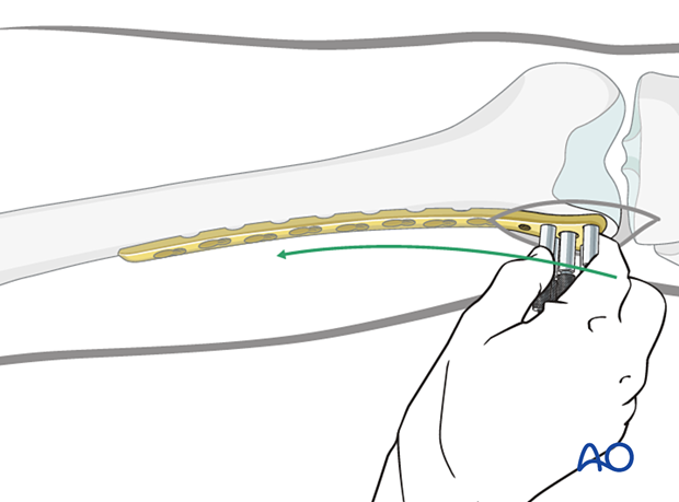
Proper position check - Position on the distal femur
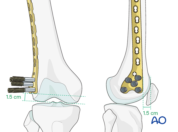
When the plate lies flat on the lateral surface of the condyle, it has been positioned correctly on the distal femoral articular block.
- The anterior edge of the head of the Condylar VA-LCP is usually 1.0-1.5 cm from the anterior aspect of the medial femoral condyle.
- The distal edge of the Condylar VA-LCP is usually 1.5 cm from the distal condylar articular surface.
Readjust plate position if necessary.
Insertion of first guide wire
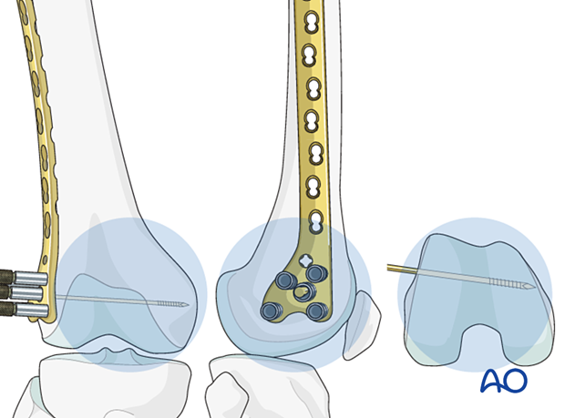
Insert a guide wire through the central hole of the plate and check it's position by image intensifier in all planes.
Verification of allignment
Determine the correct position for the central screw of the LCP with the help of guide wires around the joint. Under image intensifier control, pass one guidewire lateral to medial along the tibio-femoral joint line (red). Pass a second guidewire over the anterior the surface of the knee to indicate the plane of the patellofemoral condyles.
The ideal position of the central screw of the LCP is shown by the yellow wire. Note that it is inserted parallel to both the red wire in the frontal plane and is parallel to the green line on the end-on view on the femur. This latter orientation ensures that the plate comes to lie flush with the lateral cortex.
Insertion of second quide wire
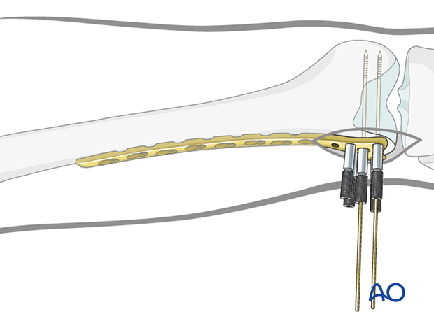
Insert a second guide wire in one of the 5.0 mm screw holes to provisional fix the plate to the femoral articular block.
Verification of second guide wire trajectory
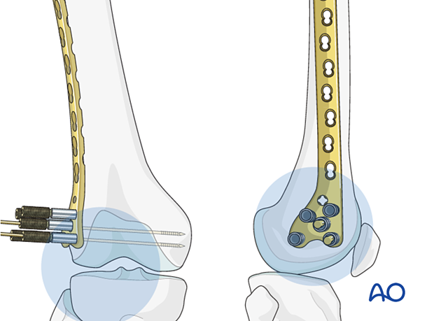
Confirm plate head placement, using visual examination and an image intensifier. Ensure that the guide wires inserted through any of the four most distal 5.0 mm screw holes in the head of the plate are parallel to the tibio-femoral joint plane.
5. Preliminary plate fixation
K-wire insertion in proximal fragment
Make an incision over the proximal two holes of the plate. Deepen this incision through the iliotibial band and the vastus lateralis muscle belly (not using the internervous intermuscular plane) to allow palpation of the proximal aspect of the plate on the lateral aspect of the femur.
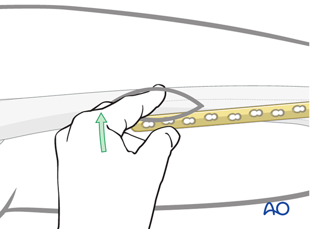
Insert a K-wire through second most proximal plate hole into the lateral cortex in order to hold the plate loosely on the lateral aspect of the femur.
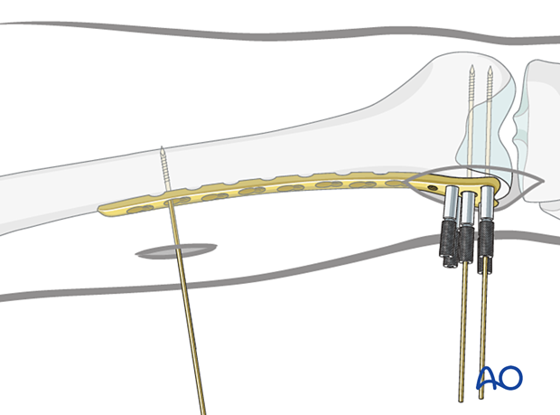
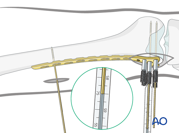
Screw length measurement in distal femoral articular block
Advance the guide wires until they reach the medial cortex of the femoral condyle, but they should not penetrate the cortex.
Use the measuring device to indirectly measure the lengths of the screws using the guide wires.
For proper measurement, the measuring device must contact the end of the threaded wire guide. This will place the tip of the screw at the tip of the guide wire.
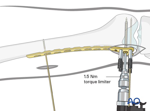
Distal screw insertion
The central wire guide is removed from the plate head and the central screw (7.3 mm) is inserted over the guide wire, using the torque-limiting power screwdriver.
Self-tapping screws are used.
Inserting only one screw at this point allows correction of small deformities in the sagittal plane (on the lateral x-ray).
After confirming that the plate is in the correct position on the distal femur, when viewed on a lateral x-ray, the additional screws (5.0 mm) should be inserted into the distal femoral articular block.
Regular locking screws or variable angle screws may be chosen based on any previously inserted lag screws.
6. Fixation of plate to proximal fragment
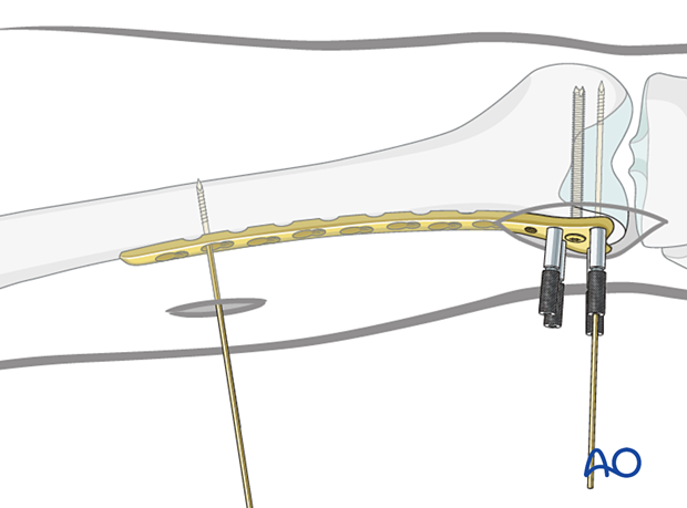
First proximal screw insertion (bridging technique)
After ensuring that the appropriate length and rotation have been obtained, insert a standard bicortical screw into the proximal segment. Generally, use the most proximal plate hole through the previously made approach to the femur.
Remove the previously inserted K-wire. Palpate and maintain the position of the plate on the lateral aspect of the femur.
Drill, measure screw length and insert the chosen self-tapping screw in neutral mode through both cortices.
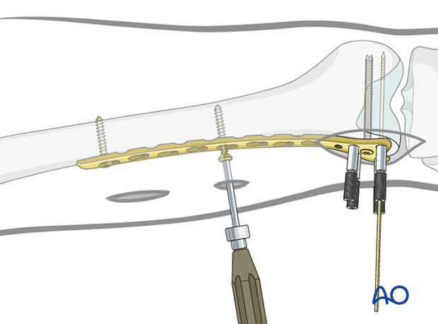
Insertion of further screws in the proximal segment
Under image intensifier guidance (as necessary) insert the chosen self-tapping 4.5 mm screws. (Their lengths can be estimated, but must be checked, and are generally 38 to 42 mm.)
7. Completed osteosynthesis
Additional screw placement
Distal segmentInsert additional screws for a minimum total of 4 screws distally. These may be locking or variable angle locking head screws.
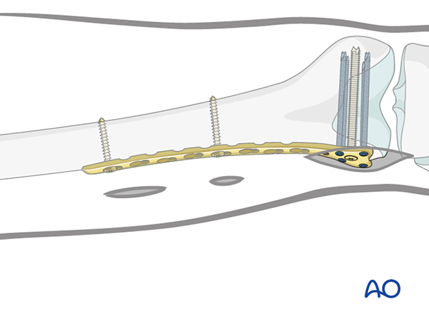
Insert additional screws for a minimum total of 3 proximally, either standard bicortical screws inserted in neutral mode (as illustrated), or locking-head screws may be used. Locking head screws are only useful in osteoporotic bone.
A standard screw is inserted after drilling with a 3.2 mm drill bit.
A 5.0 mm locking-head screw is inserted after drilling with a 4.3 mm drill bit through the threaded drill sleeve.
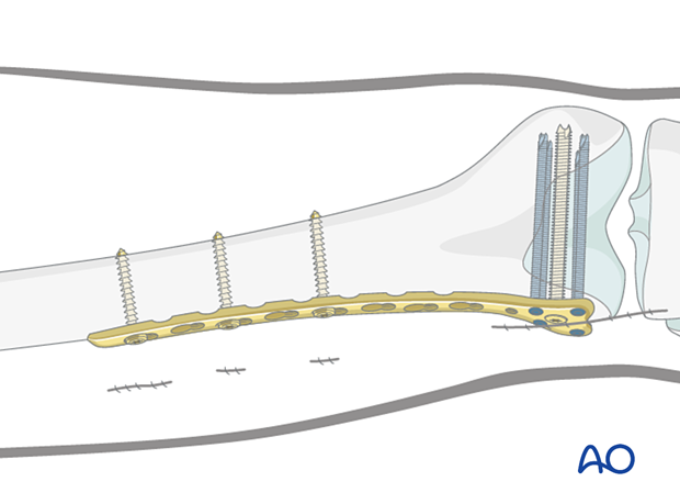
Final check of fracture reduction and fixation
Gently move the knee through a full range of motion. Carry out a clinical assessment of the rotational profile. Finally, perform a radiographic assessment of the frontal-plane alignment (varus/valgus) and sagittal-plane alignment (extension/flexion).
Examine the knee for any ligamentous instability.
