Nailing
1. General considerations
Introduction
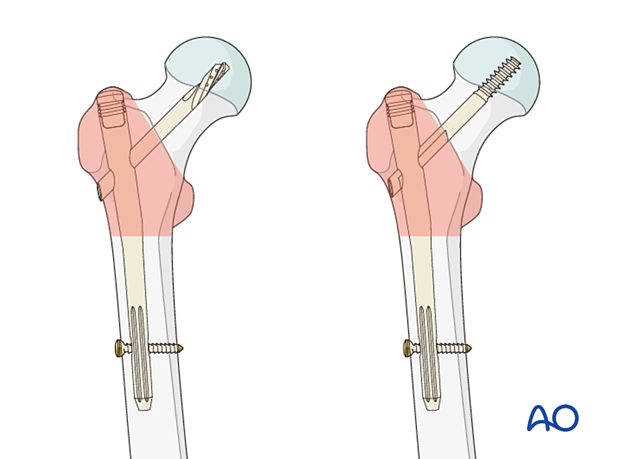
A pertrochanteric fracture without a distal extension or without another fracture distally can be treated successfully with a short intramedullary nail.
A longer nail is required for fractures with subtrochanteric extension or associated femoral shaft fracture, and some surgeons prefer them routinely. Some manufacturers provide intermediate-length nails.
The trochanteric femoral nail advanced (TFNA) device is an intramedullary nail that uses a spiral blade or lag screw to obtain fixation in the femoral head.
The operative technique for other cephalomedullary devices is generally similar, but it is important to review the manufacturer’s guides for details.
Some systems offer the option to insert cement through the implant for augmentation in case of poor bone quality.
Another option is fracture compression/reduction along the helical blade/lag screw. This may be helpful if fracture gaps need to be closed after implant insertion.
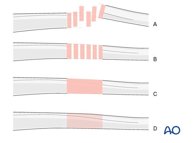
Throughout this treatment option illustrations of generic fracture patterns are shown, as four different types:
A) Unreduced fracture
B) Reduced fracture
C) Fracture reduced and fixed provisionally
D) Fracture fixed definitively
Closed vs open reduction
Fracture reduction should start with a closed attempt.
If manipulation does not lead to a satisfactory reduction, a percutaneous reduction technique should be performed.
The definitive decision for the treatment will be made after positioning the patient and an initial closed reduction. Since emergency department x-rays are often of suboptimal quality, verifying the preoperative diagnosis using image intensification is necessary.
Spiral blade vs lag screw
There is not yet a clear indication of when to use a spiral blade and when to select a lag screw in the elderly patient. It is, therefore, often surgeon’s preference.
In a young patient with hard bone, a blade is relatively contraindicated, and a screw should be used instead (with tapping).
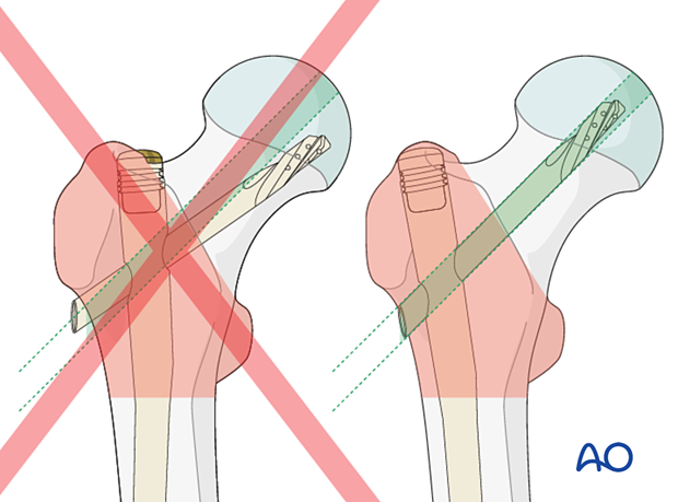
Correct position of lag screw or blade
The thread of the lag screw (or tip of the spiral blade) needs to end in the trabecular bone structures to gain enough purchase. Therefore, it is important that the lag screw comes to lie in the center of the head-neck axis or slightly inferior to it. This allows for increased depth of the screw.
Distal locking
Short nails should be routinely interlocked distally to ensure stability. Static or dynamic distal locking is at surgeon’s preference.
Imaging
If the trauma plain films show a potentially unstable fracture but do not give enough detail about the fracture morphology, 3-D CT is a powerful tool for better diagnosis and planning a strategy for a successful surgery.
Preoperative planning
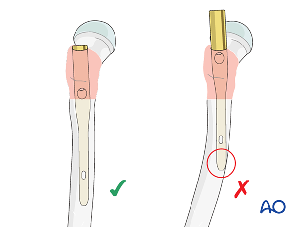
Anterior bow of the femurCheck the degree of the anterior bow of the femur on an x-ray of the uninjured extremity.
If there is excessive anterior bowing, the risk for anterior impingement is high and should be considered when choosing the entrance site.
AO teaching video
Femur, proximal – Fractures – Intramedullary fixation using the TFN-Advanced (TFNA) proximal femoral nailing system
(28 minutes)
2. Patient positioning
Position the patient supine on the fracture table with the uninjured leg placed on a leg holder.
Unlike positioning to employ a DHS, it is important to ensure that the ipsilateral hip is adducted to allow nail entrance. To facilitate this, push the torso 10°–15° to the contralateral side.
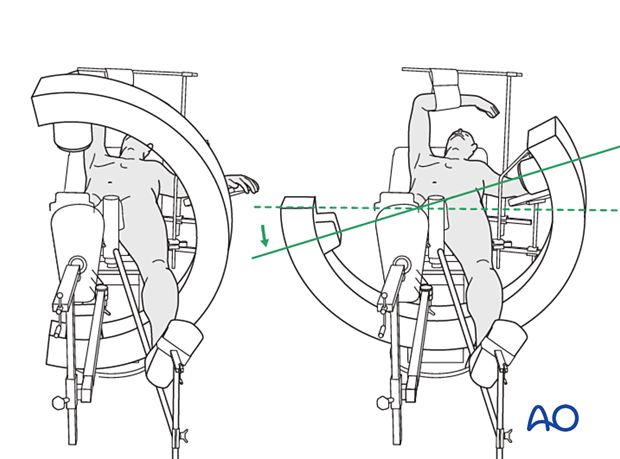
For C-arm positioning to acquire optimal AP, lateral, and axial views, read the additional material on:
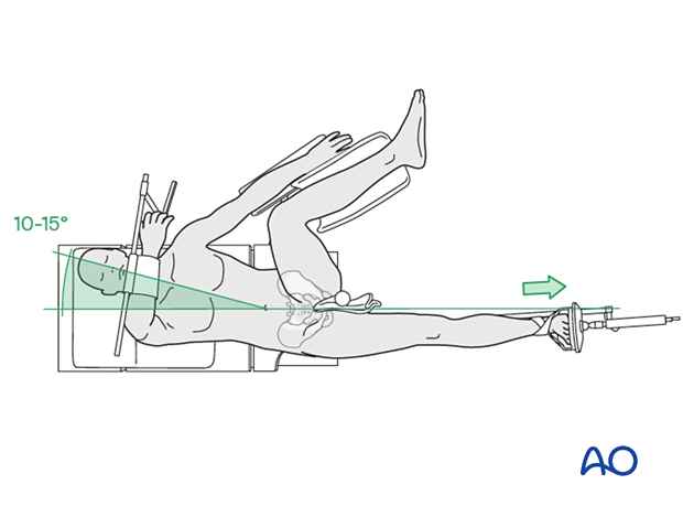
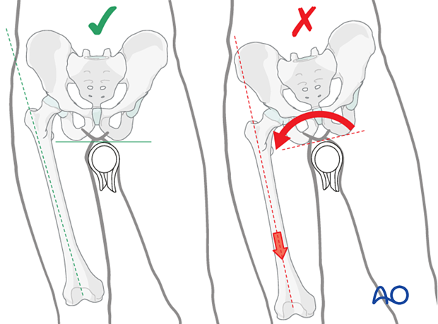
Placing both legs in traction prevents pelvic rotation that leads to abduction.
Flex the injured hip slightly and adduct it to allow nail entrance. Extend the hip on the uninjured side and abduct it to allow lateral imaging.
3. Reduction
Closed reduction
Closed reduction is usually achieved by:
- Pulling in the direction of the long axis of the leg to distract the fragments and regain length
- Adjustment of internal rotation of the femoral shaft ...
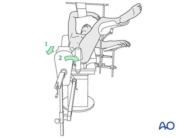
... until the patella is facing forward on an AP view of the knee joint
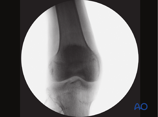
Check the reduction in both the AP and lateral view with an image intensifier.

Assessment of reduction quality
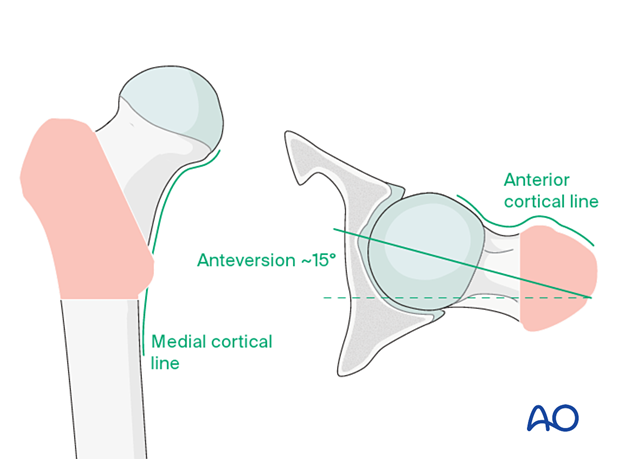
Read the fracture line on the image intensifier views. Identify gaps or increased density due to overlapping of fragments.
Follow the medial cortical line on AP view and the anterior cortical line on the axial view. Identify any translational or angular malalignment.
Acceptable reduction quality shows the following patterns:
- No gap or increased density visible along the fracture line
In the AP view:
- Continuous medial cortical line
- No varus angulation
In the lateral view:
- Anteversion approximately 15°
- Continuous anterior cortical line
For more details, see the additional material on assessment of reduction quality.
Percutaneous reduction
If closed reduction is not satisfactory, carry out a percutaneous reduction technique.
Open reduction
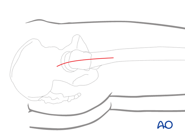
If percutaneous reduction fails, carry out a limited open reduction through a lateral approach.
Enlarge the lateral incision as necessary, splitting the fascia lata along its length and retracting the vastus lateralis anteriorly and medially. Direct visualization of the anterior fracture is mandatory.
4. Implant selection
Shaft-neck angle
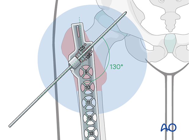
If possible, determine the most appropriate neck-shaft angle (angle subtended between the femoral-neck and shaft axes) using an AP view of the uninjured hip.
In most cases, an implant with a neck-shaft angle of 130° will be appropriate.
Confirm this angle intraoperatively after reduction.
If not possible preoperatively, determine the angle intraoperatively after reduction. Place the radiographic ruler and K-wire over the proximal femur and take an AP view.
Determination of nail diameter
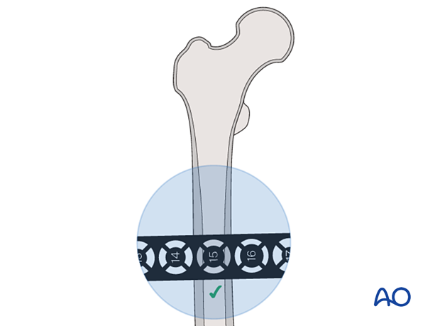
Determine the intramedullary diameter by placing the radiographic ruler over the injured femur at the level of the nail tip and reading the diameter where the indicator fills the canal.
The distance between ruler and bone influences the correct estimation of diameter and needs to be considered.
5. Approach to the entry point
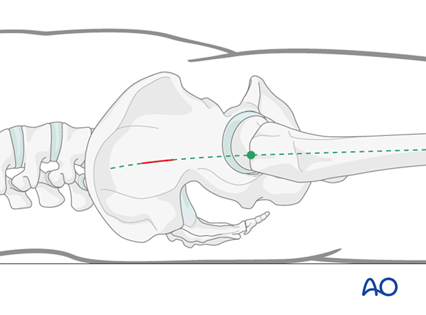
To approach the entry point, incise the skin in line with the femoral shaft axis and about 5 cm proximal to the tip of the trochanter.
6. Nail insertion
Determining the entry point
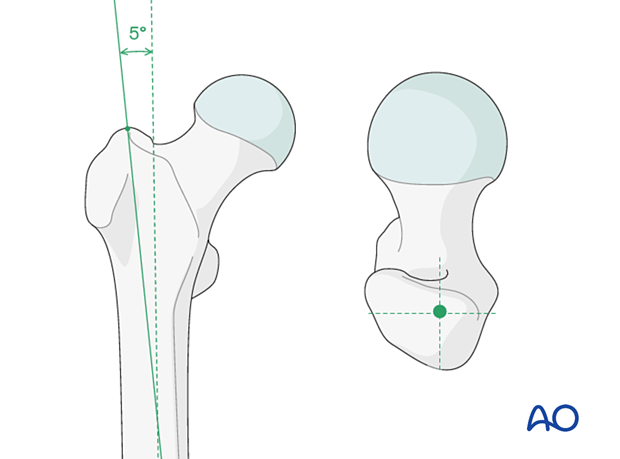
The entry point is on the tip of the greater trochanter or slightly medial to it. This deviates about 5° from the axis of the medullary canal, consistent with the nail geometry. Take great care to avoid a lateral entry or reamer migration into the soft bone lateral to the tip, both of which force varus malalignment when the nail is ultimately inserted.
Guide-wire insertion
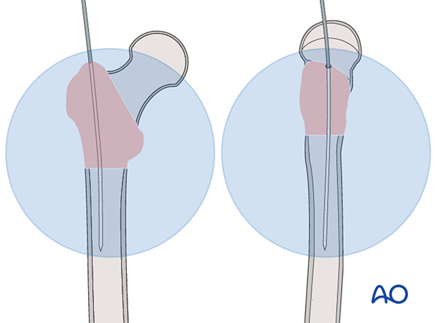
Insert the guide wire through the tip of the greater trochanter and in line with the middle of the femoral neck, and slightly lateral to a line corresponding to the anatomical axis of the shaft.
Advance the guide wire in the femur shaft.

Checking guide-wire position
Check the position of the guide wire using the image intensifier.
Ideally, the guide wire’s position in the femoral shaft should be central and deviate slightly proximally according to the degree of the lateral bend of the implant in the AP plane. In the axial view, it must be in line with the middle of the femoral neck.
Opening of the femur
Insert the protection sleeve with its trocar over the guide wire and push it through the soft tissues until it abuts against the greater trochanter. Withdraw the trocar and insert an appropriate drill bit or reamer over the guide wire.
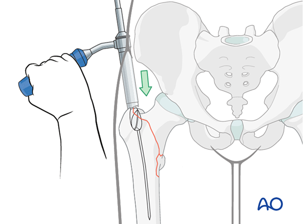
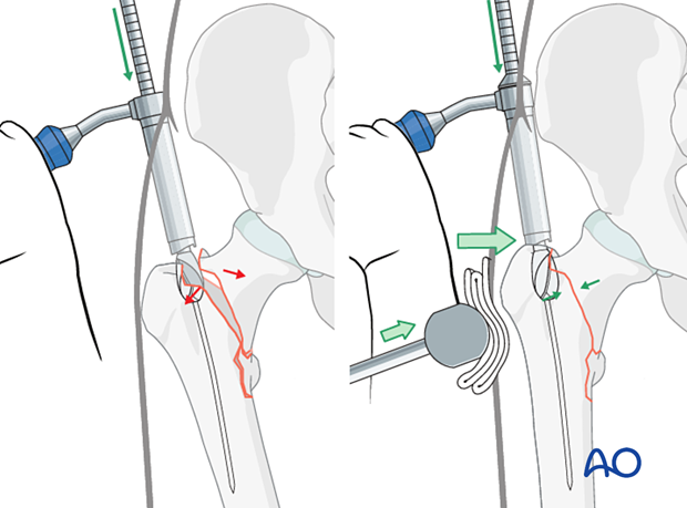
As the nail entry site is usually close to or runs through the fracture line, introducing the reamer may result in displacement of the fragments without creating a channel for the nail (“fish-mouth” deformity).
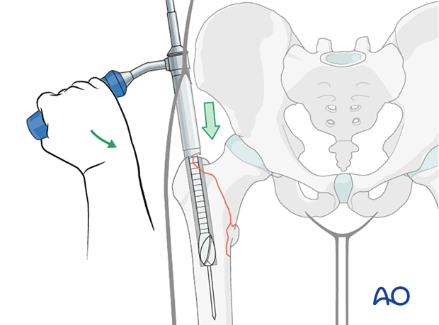
To avoid this, apply a medially directed force to the lateral trochanteric region and close the fracture gaps. This force may be applied with the handle of the soft-tissue protection sleeve or a hammer by an assistant. Pay attention to ream with power the dense medial bone of the channel and avoid lateral migration.
Reaming of the medullary canal
Insertion of the nail
Mount the nail on the insertion handle.
In most patients, the nail can be inserted manually.
Insert the nail over the guide wire.
Once the nail engages with the medullary canal, remove the guide wire and advance the nail fully.
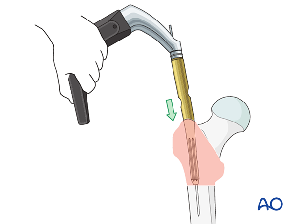
Insert the nail to such a depth that it will allow the blade or lag screw to be placed in the center of the femoral head.
With the aiming arm on the insertion handle, check correct insertion depth of the nail on AP view with a wire placed on the skin parallel to the guide-wire track.
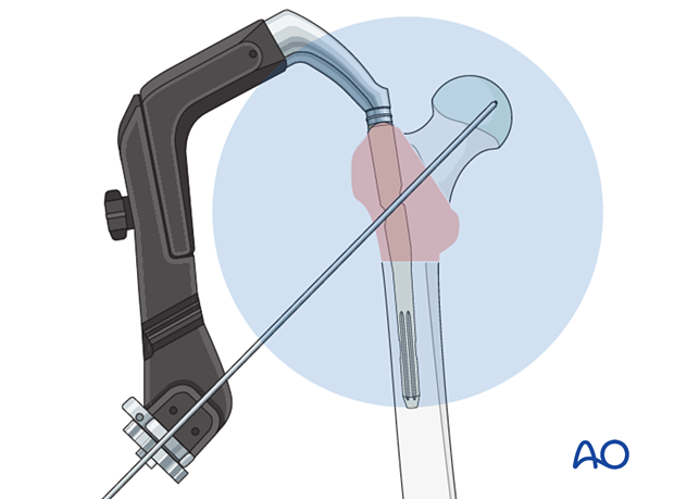
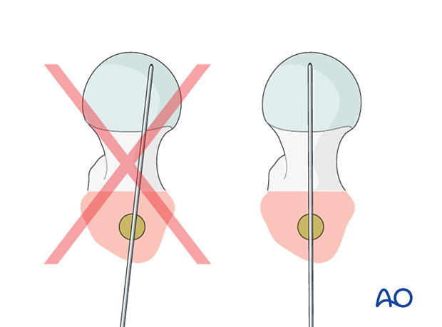
Check the axial view for alignment of the aiming arm with the head-neck axis. Adjust the rotation of the nail if necessary. A wire placed through the insertion handle parallel to the planned blade axis helps with identifying malrotation.
7. Guide-wire insertion
Positioning of the guide wire
Insert the drill-sleeve assembly through the aiming arm and advance it through the soft tissues to the lateral cortex.
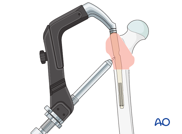
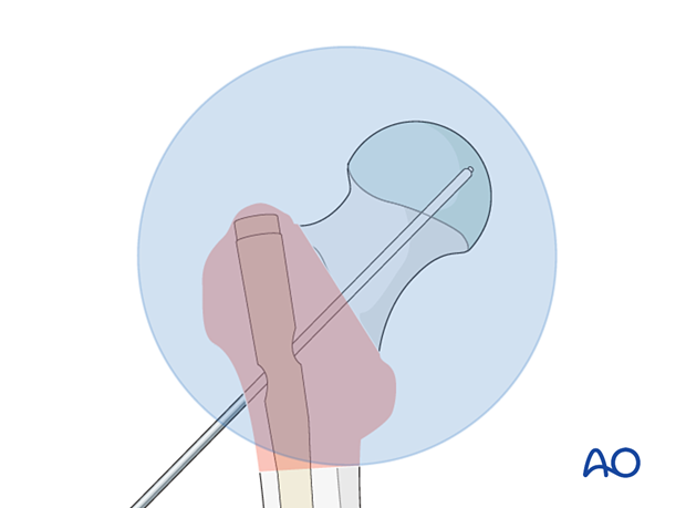
Advance the guide-wire tip deeply across the dense trabecular bone of the head and into the subchondral bone of the femoral head, stopping 5 mm before the joint.
The ideal position of the guide wire in the AP plane is in line with the axis of the neck. In the lateral and axial views, it should be in line with the axis of the neck.
This ensures that the subsequent blade or lag-screw thread fully engages the very strong primary compressive trabecular bone.
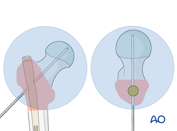
A wire position slightly inferior to the center of the femoral head is also acceptable. Further peripheral malposition prevents deep lag screw or blade placement and introduces rotational instability when axial load is applied.
Measuring length of the blade/screw
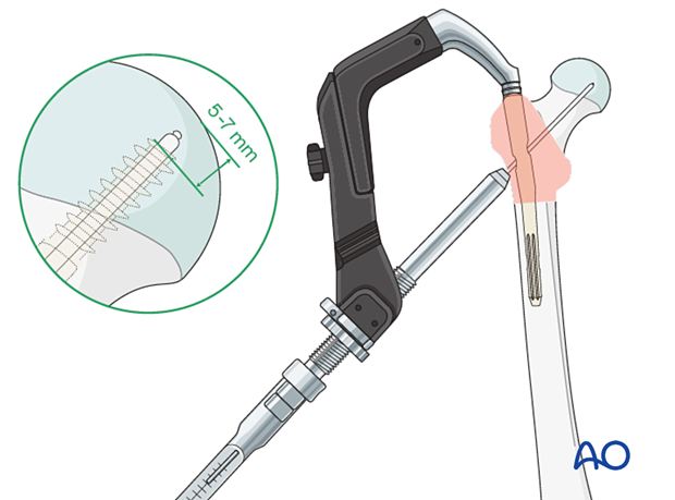
Measure the insertion depth of the guide wire. Choose a blade/screw length as indicated.
The goal is to place the tip of the blade/screw centrally and within 5–7 mm from the joint.
8. Blade insertion
Drilling hole for the blade
Open the lateral cortex with the 11.0 mm drill bit.

Insertion of blade
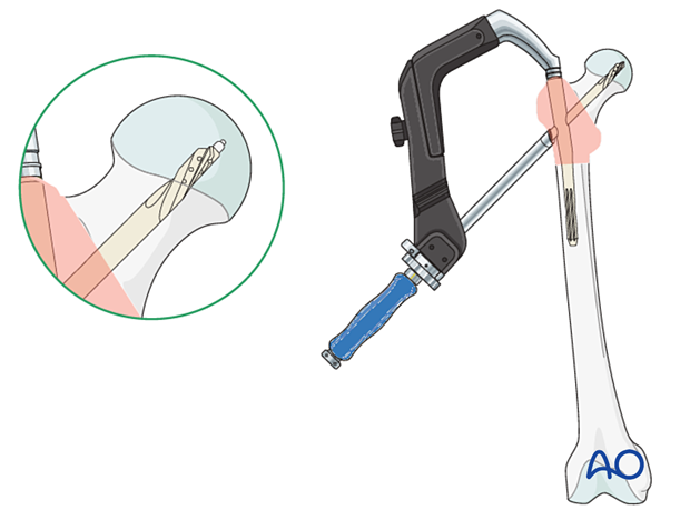
Connect the blade to the inserter.
Insert the blade over the guide wire to the stop.
Locking of rotation
Tighten the locking mechanism in the upper part of the nail to lock the blade rotation.
By turning the screw half a turn counterclockwise, sliding of the blade in the nail will be allowed again.
Remove the guide wire.
Remove the inserter handle and drill sleeve.

Option: augmentation
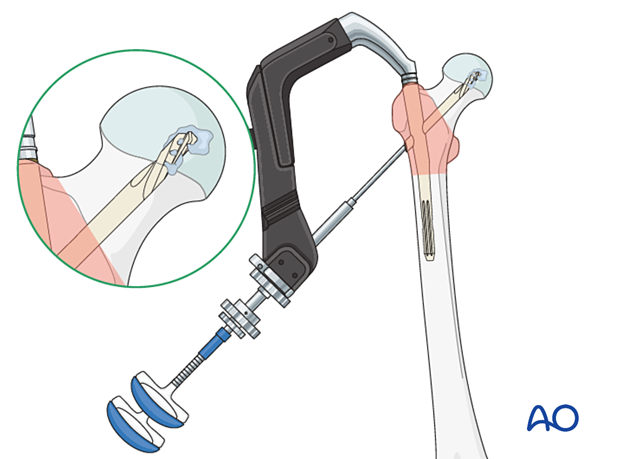
In severe osteoporotic bone, if not enough resistance is felt during blade insertion, consider cement augmentation before removing the inserter and drill sleeve.
Follow the instructions of the manufacturer’s technical guide.
9. Lag-screw insertion
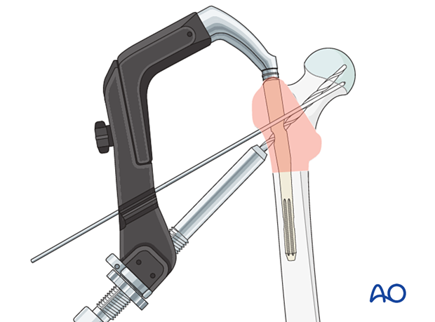
Insertion of an antirotation wire
To avoid inadvertent rotational displacement during lag-screw insertion, add an extra K-wire through the designated hole in the aiming arm.

Drilling hole for lag screw
Open the lateral cortex with the 11.0 mm drill bit.
Predrill the screw track up to 10 mm short of the tip of the guide wire with the stepped reamer. Otherwise, the guide wire may fall out when the drill bit is removed.
Insertion of lag screw
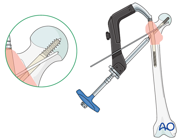
In young, dense bone, tap the screw track to the desired screw depth.
Connect the screw to the inserter.
Insert the lag screw over the guide manually until the marking on the screw inserter reaches the guide sleeve.
In this implant, the inserter handle should be in line with the aiming arm to allow proper locking. Other systems may have different locking alignments.
Locking of rotation
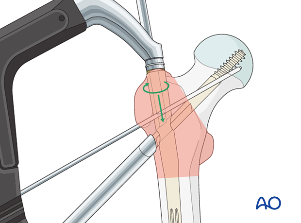
Tighten the locking mechanism in the upper part of the nail to lock the lag-screw rotation.
By turning the screw half a turn counterclockwise, sliding of the lag screw in the nail will be allowed again.
Remove the inserter handle and drill sleeve.
Remove the wire(s).
Option: Interfragmentary compression
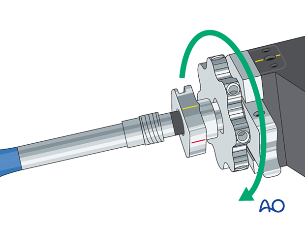
If, after rotational locking of the lag screw, a fracture gap needs to be closed, interfragmentary compression may be performed by turning the compression nut clockwise before removal of the inserter handle and drill sleeve.
Take care not to overcompress. This may lead to pull-out of the lag screw, especially in osteoporotic bone.
10. Distal locking
Static vs dynamic distal locking
For simple and multifragmentary pertrochanteric fractures, static locking is sufficient. This should be inserted according to the manufacturer’s instructions.
Drilling hole for distal locking
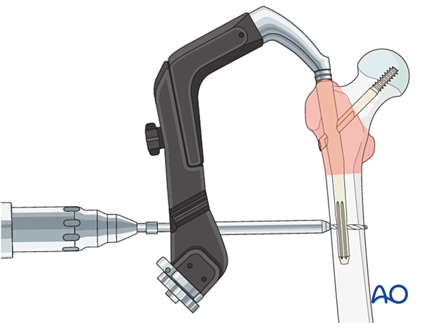
Make a stab incision and insert the drill sleeve and trocar through the selected locking hole in the aiming device. Make sure the sleeve rests on the bone to avoid drill migration.
Drill both cortices.
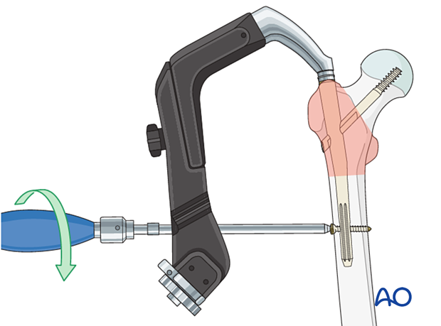
Insertion of locking screw
Insert a cortical screw of appropriate length bicortically.
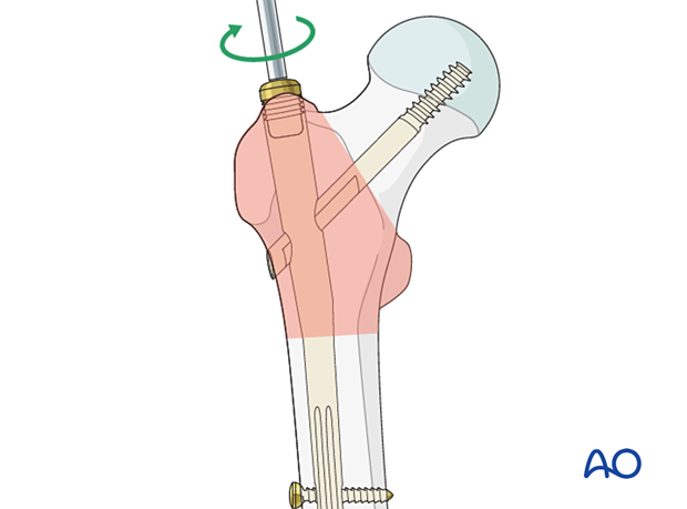
11. Insertion of end cap
Insert an end cap if indicated.
As nearly none of the implants will be removed, this step is generally unnecessary and is up to surgeon’s preference.
12. Final assessment
Check the reduction and final position of the nail in AP and lateral views.

13. Aftercare
Postoperative mobilization
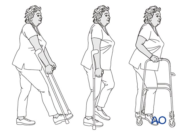
The elderly patient may start with weight bearing as tolerated with walking aids the day after surgery.
Initial restricted weight bearing is required for the young patient. This can be reassessed at 6 weeks.
Unrestricted range-of-motion exercises of the hip joint are allowed.
Pain control
To facilitate rehabilitation and prevent delirium, it is important to control the postoperative pain properly, eg, with a specific nerve block.
VTE prophylaxis
Patients with lower extremity fractures requiring treatment require deep vein prophylaxis.
The type and duration depend on VTE risk stratification.
Follow-up
Follow-up assessment for wound healing, neurologic status, function, and patient education should occur within 10–14 days.
At 3–6 weeks, check the position of the fracture with appropriate x-rays.
Recheck 6 weeks later for progressive fracture union.
Longer follow-up, at 6 months and 1 year, is indicated to assess the development of posttraumatic arthritis and/or avascular necrosis.
Implant removal
Implant removal is not necessary unless clinically indicated.
Prognosis of proximal femoral fractures in elderly patients
For prognosis in elderly patients, see the corresponding additional material.


