Plating
1. General considerations
Introduction
Articular fractures, simple or comminuted, of a metacarpal head may be fixed with a T-, Y- or an anatomical neck plate.
The articular fragments are reduced and fixed using the transverse part of the plate. In a second step, the extraarticular fracture component is reduced and fixed.
Noncomminuted fracture components, eg, between the articular fragments or between the articular block and the diaphysis, may be fixed with compression.
The reduction can be assisted with arthroscopy if skill and equipment are available.
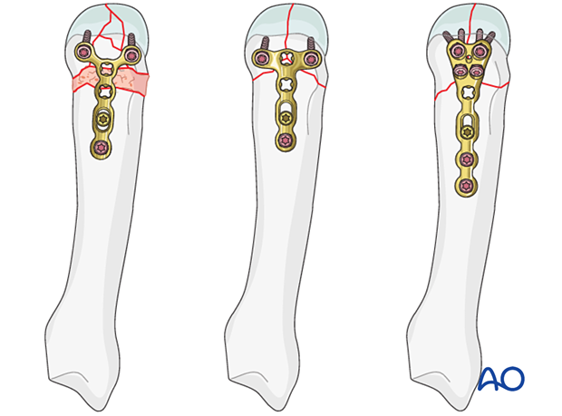
Plate selection
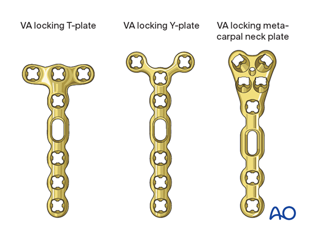
Select a plate according to the size of the bone, fracture geometry, and surgeon’s preference. A T-shaped plate may be used. Other shapes may also be applied.
A plate with variable-angle (VA) locking-head screws has the advantage to allow insertion of two or three screws in variable angles into the articular block. The rounded plate edges avoid soft-tissue irritation and adhesion.
The plate needs to be contoured to fit the anatomy of the end segment.
2. Approach
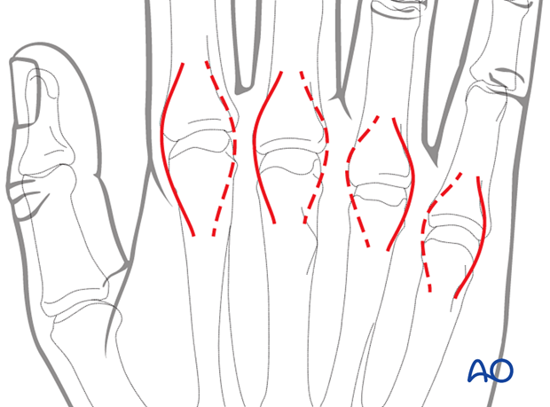
For this procedure, the following approach may be used:
3. Reduction and fixation of the articular block in a simple T- and Y-shaped fracture
If the fracture line allows, eg, in a T- or Y-shaped fracture with the articular fracture line running from palmar to dorsal, a lag screw may be inserted to stabilize the articular fracture. This converts a three-part fracture to a two-part fracture.
Make sure the screw track is not interfering with later plate application.
4. Reduction of a comminuted fracture
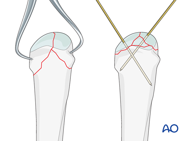
Manipulate the articular fragments with a dental pick, small K-wires, or a small periosteal elevator.
Small K-wires can also be used for preliminary fixation. Depending on fracture configuration, pointed forceps may be useful for reduction.
Impaction
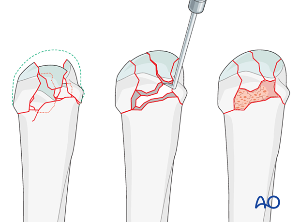
In impacted fractures, reduce the articular surface, and fill the bony defect under the fragments with bone graft. This helps to keep the fragments in place when the screw fixation is performed.
Buttressing small fragments
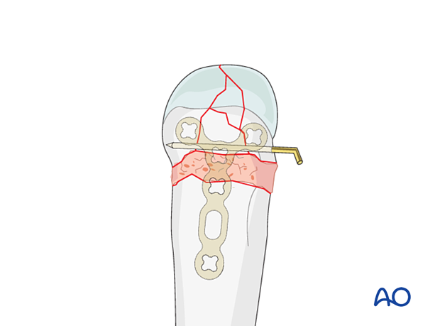
Additionally, a periarticular K-wire may be used to reposition and support impacted articular fragments.
The end of the K-wire may protrude through the skin, which facilitates removal after consolidation of the fracture.
Confirming anatomical reduction
Check anatomical reduction of the joint surface under direct view or arthroscopy and image intensification.
Maximally flex the MCP joint to gain a view of the palmar aspect of the metacarpal head.
5. Checking alignment
Identifying malrotation
At this stage, it is advisable to check the alignment and rotational correction by moving the finger through a range of motion.
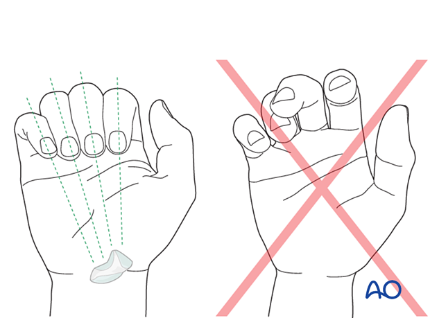
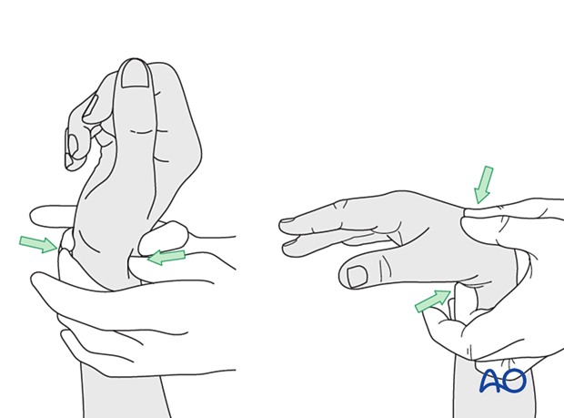
Rotational alignment can only be judged with flexed metacarpophalangeal (MCP) joints. The fingertips should all point to the scaphoid.
Malrotation may manifest by an overlap of the flexed finger over its neighbor. Subtle rotational malalignments can often be judged by a tilt of the leading edge of the fingernail when the fingers are viewed end-on.
If the patient is conscious and the regional anesthesia still allows active movement, the patient can be asked to extend and flex the finger.
Any malrotation is corrected by direct manipulation and later fixed. Flexing the MCP joints while preventing overlap of the fingers will reduce rotational displacement.
Using the tenodesis effect when under anesthesia
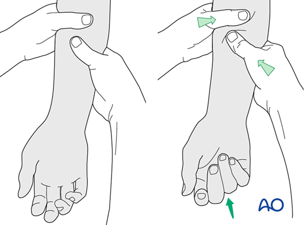
Under general anesthesia, the tenodesis effect is used, with the surgeon fully flexing the wrist to produce extension of the fingers and fully extending the wrist to cause flexion of the fingers.
Alternatively, the surgeon can exert pressure against the muscle bellies of the proximal forearm to cause passive flexion of the fingers.
6. Plate preparation
Plate trimming
Adapt the plate length to the length of the metacarpal. Avoid sharp edges, which may be injurious to the tendons. There should be at least 3 plate holes proximal to the fracture available for fixation in the diaphysis. At least two screws need to be inserted into the diaphysis.
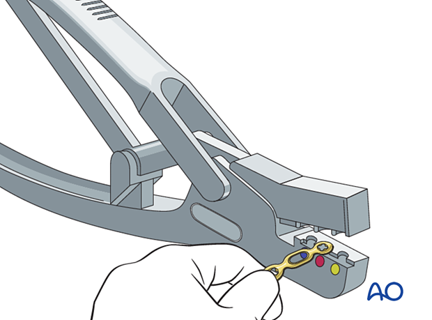
Contouring
Contour the plate exactly to fit the surface of the metacarpal, including any necessary twisting.
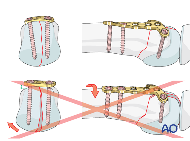
7. Bridge plating
Plate application
Place the plate exactly so that the articular fragments can be fixed using screws through the distal plate holes. Often, it is not possible to insert a screw into each fragment. Small fragments should be supported by adjacent large fragments or bone graft.
Be careful to ensure that the screws do not perforate the joint surface.
Keep the plate in place with the atraumatic forceps.
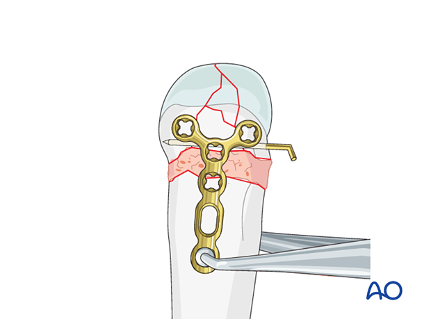
If using a metacarpal neck plate, position it with the distal end proximal to the cartilage.
This plate may be applied ulnarly in the 5th metacarpal.
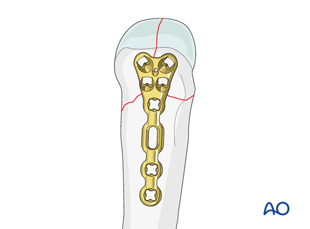
Begin fixation with the most critical articular fragment.
Drill carefully not to displace the fragments and penetrate the articular surface.
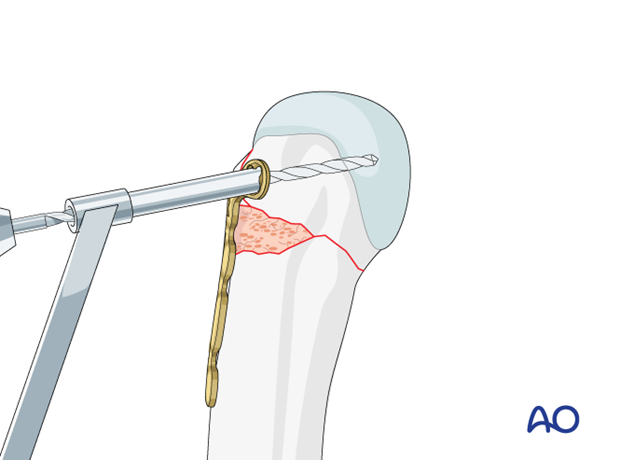
Insert the first screw.
Confirm the reduction and correct screw position using image intensification.
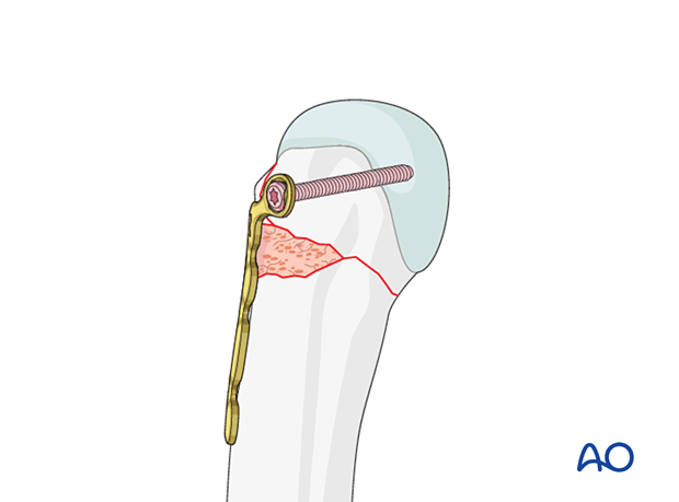
Align the plate along the shaft and bring the bone out to length.
Insert the VA locking head screws into the diaphyseal part of the plate without compression.
Check rotational alignment clinically and with an image intensifier.
Insert the second VA locking screw in the other end of the T-shape.
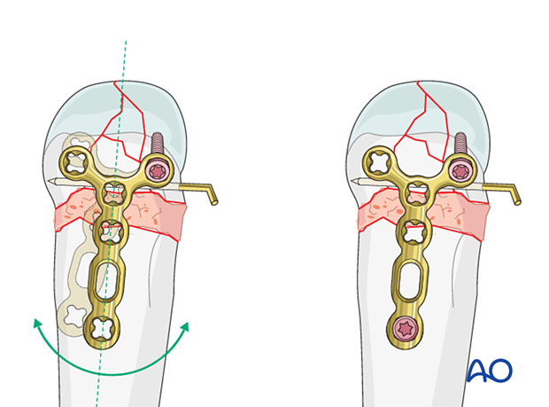
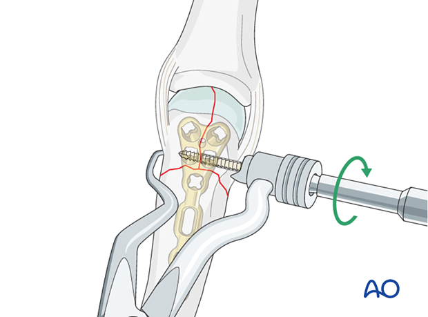
Extrinsic compression
If the articular fracture allows, apply extrinsic compression.
Compress the fracture with reduction forceps. Position one tip of the forceps on the plate with the first screw to avoid damage of the bone cortex.
Insert the second VA locking screw to hold the compression.
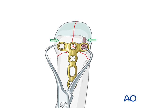
Sagittal articular fracture of the 2nd and 5th metacarpal head
It is helpful to apply the neck plate radially on the 2nd and ulnarly on the 5th metacarpal to allow for extrinsic compression with reduction forceps of a sagittal articular fracture and hold the compression with the distal VA locking-head screws.
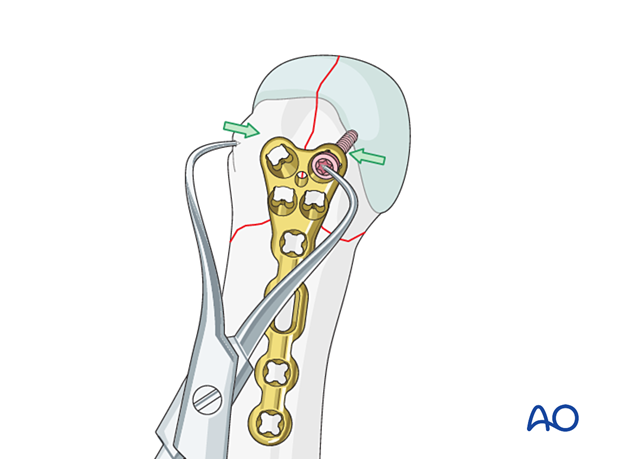
Insertion of further diaphyseal screws
Insert the second and, if possible, a third screw into the diaphyseal fragment and tighten them.
When the fixation is completed, remove the external fixator and K-wires, other than those needed to buttress small articular fragments.
Cover the plate with periosteum to avoid adhesion between the tendon and the implant leading to limited finger movement.
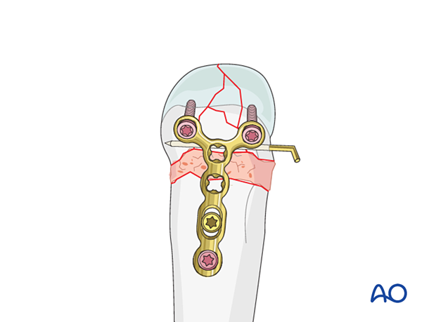
Fixation of further fragments
If additional large metaphyseal fragments need fixation, insert screws through the plate, or insert an independent lag screw.
If needed, use additional bone graft to fill any defect.
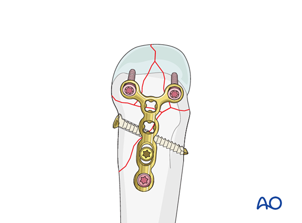
8. Compression plating of a simple metadiaphyseal fracture
Insert the first cortical screw in the oblong hole in compression mode to compress the extraarticular fracture component.
Check again rotational alignment clinically and with an image intensifier.
Insert a second screw into the diaphyseal segment to finalize the fixation.
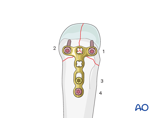
9. Final assessment
Confirm correct rotational alignment by clinical examination.
Image intensification may be used to confirm anatomical reduction and correct placement of implants in two views.


