Cortical lag screw insertion
1. Principles
The function of the cortical lag screw is to compress one piece of bone against another. This improves the stability of a reduction, so it is commonly used to achieve absolute stability, leading to direct bone healing, as opposed to healing with callus.
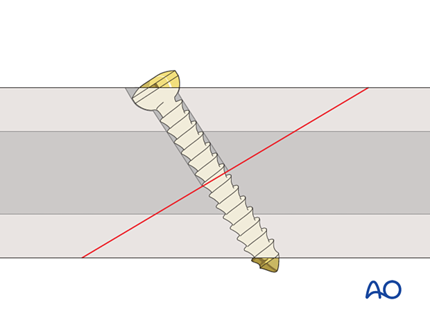
Various screw types are available, and details of the lag screw technique will depend on the type of screw used.
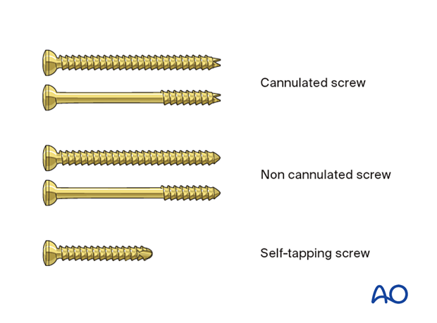
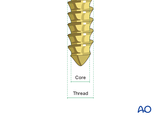
A screw has a specific core diameter and an outer or thread diameter. To facilitate clear communication, screws are named by their thread diameter.
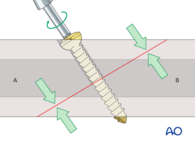
As the screw is tightened, the compressive effect occurs between the head of the screw in segment A and the threads at the far end of the screw in segment B.
To achieve this the screw must be able to move in the near hole (gliding hole) without the threads obtaining purchase, so a thread-diameter hole must be drilled in segment A.
For the screw threads to obtain purchase in the far cortex, a pilot hole of the core diameter must be drilled in segment B.
This 3D model shows cortical lag screw fixation.
The axis of the screw should be as perpendicular as possible to the plane of the fracture.
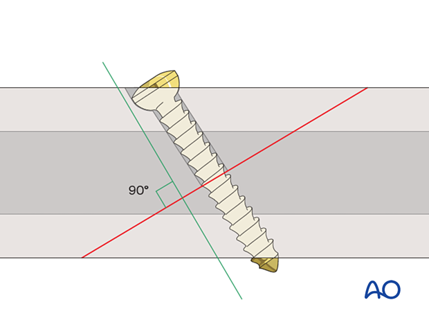
If the screw is far from perpendicular, there will be a shearing force as it is tightened, which risks displacing the fracture.
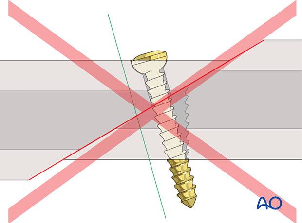
These 3D models show the biomechanical behavior of the construct. In the top animation, the lag screw is correctly positioned perpendicular to the fracture plane. In the bottom panel, the screw is not perpendicular to the fracture plane, and as it is tightened there will be a tendency for the fragments to displace.
AO Teaching Video
Lag screw technique
2. Reduction and temporary fixation
Reduce and hold the fracture temporarily.
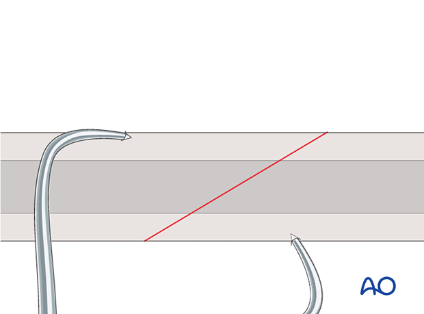
3. Insertion of cannulated screws
If a cannulated screw is to be used, insert a guide wire and use cannulated drill bits. Further steps are identical to what is described for fully and partially threaded screw insertion.
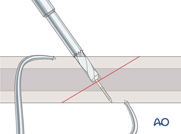
4. Insertion of fully threaded screws
Drilling
Gliding holeDrill the gliding hole in the near piece of bone using a drill bit with the same diameter as the threads of the screw.
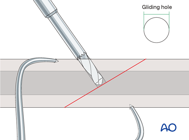
These 3D models show the effect of drilling a thread-diameter hole in the near cortex. To achieve fracture gap compression (top animation), it is essential to drill a thread-diameter hole in the near cortex. If this is not done, the screw threads will engage both cortices which prevents the compression of the fracture fragments (bottom panel).
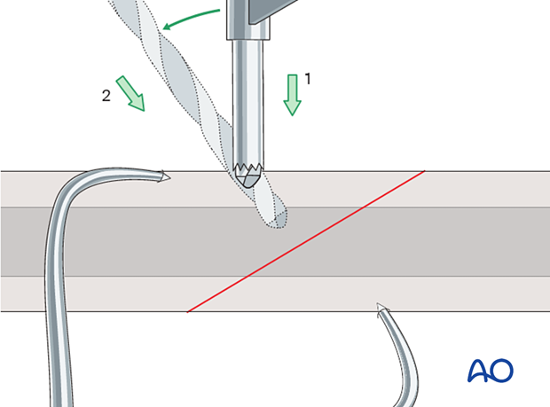
To ensure that the pilot hole has the same axis as the gliding hole, insert a drill sleeve that has the outer diameter of the gliding hole and the inner diameter of the intended pilot hole. For the threads to engage in the pilot hole, the diameter of the distal hole must correspond to the core diameter of the screw.
Drill the pilot hole. The drill bit should penetrate the far cortex.
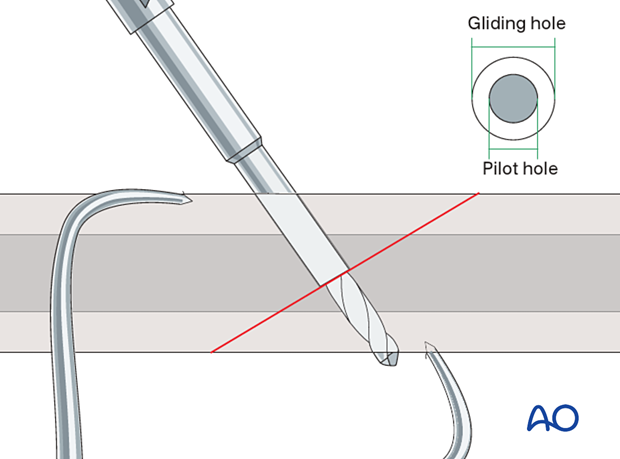
It is possible to drill both holes with the smaller drill bit first, then to use the larger drill bit to create the gliding hole in the near cortex.
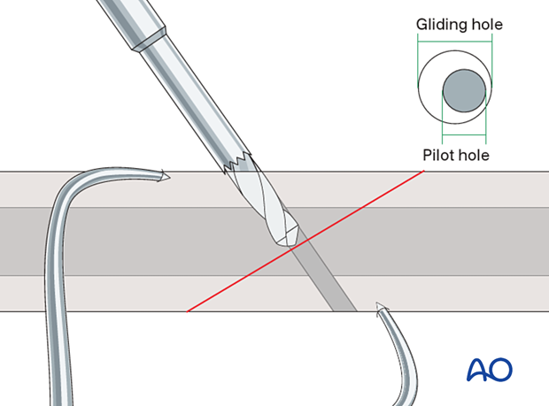
Countersinking
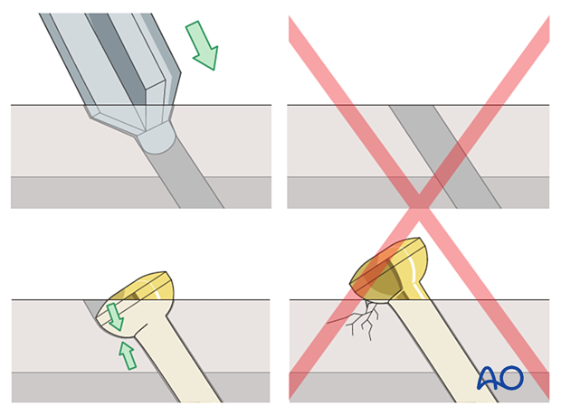
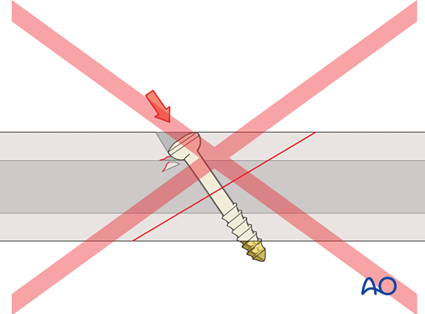
To reduce the high pressure of the hemispherical screw head contacting the flat cortical bone countersink the gliding hole. This distributes force over a greater contact area, helping to avoid microfracture.
This also results in the head of the screw being less prominent, which may be desirable in subcutaneous bone.
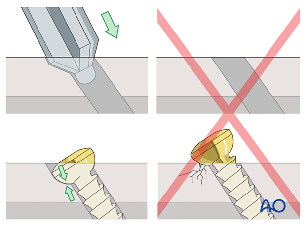
These 3D models show the effect of countersinking. In the top animation the countersinking is properly executed, allowing a homogenous force distribution on the bone. The bottom animation shows insufficient countersinking, causing an eccentric and concentrated loading on the bone, which decreases the degree of compression and might lead to bone resorption due to the high stresses.
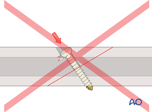
These 3D models show the effect of excessive countersinking. In the top animation the countersinking is performed correctly. In the bottom animation, there is excessive countersinking and the bone stock of the near cortex below the screw head (shown in red) might become too weak to sustain the screw force required to compress the bone fragments, causing sinking and potential failure.
Use of a dished washer
An alternative to countersinking is to use a dished washer. This has a flat underside to apply the force evenly on the bone surface and a dished or concave surface on the top which matches the shape of the screw head.
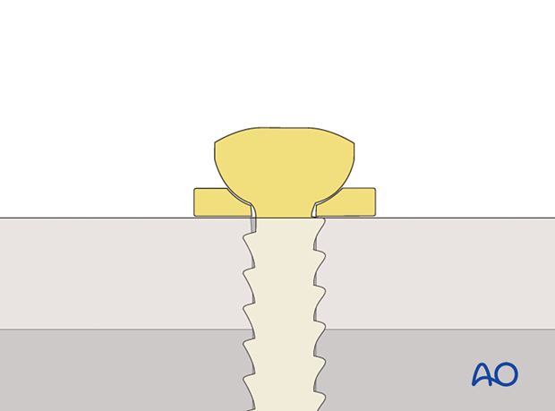
These 3D models show the effect of a washer. In the top animation, a washer is placed between the bone and the screw head to help distribute the load over a larger area. The bottom animation shows the problem of stress concentration when countersinking is not possible.
Determination of screw length
The depth of the hole is measured.
It is better for the hook on the depth gauge to catch on the longer side of the drill hole, as shown.
Alternatively, if it is not possible to engage the hook, measure the shorter side of the drill hole, but this will tend to underestimate the required screw length. The surgeon must make an allowance for this.
To ensure full thread purchase the tip of the screw should protrude 1–2 mm through the opposite cortex.
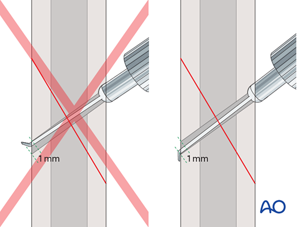
Insertion of non-self-tapping screws
TappingWhen non-self-tapping screws are used, tap the distal hole.
As the near hole is a gliding hole, the tap should pass through this freely.
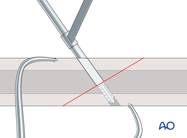
The screw is inserted at about 2/3 of the possible torque. Note that the screw should protrude 1–2 mm through the opposite cortex.

Insertion of self-tapping screws
If self-tapping screws are used, the distal hole does not need to be tapped, and the screw is inserted directly.
As the near hole is a gliding hole, the screw should pass through this freely.
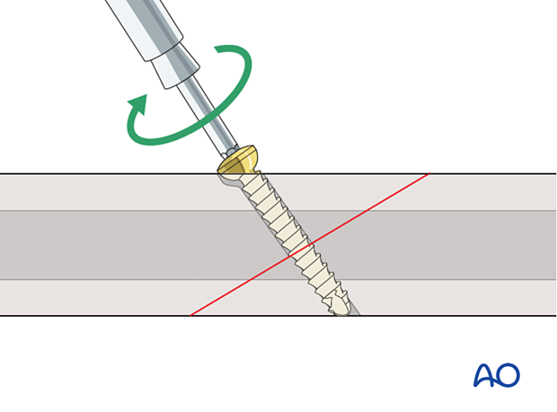
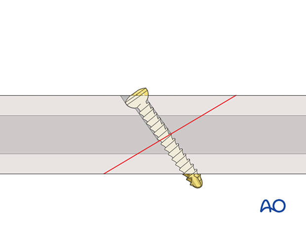
The tap portion of a self-tapping screw should lie outside of the screw hole when the screw is tightened, so a slightly longer screw is required.
However, too long a screw may cause soft-tissue irritation.
The screw is inserted at about 2/3 of the possible torque.
5. Insertion of partially threaded screws
Drilling
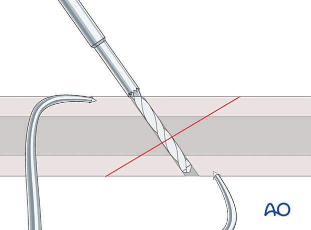
When partially threaded screws are used, a gliding hole is not necessary. Drill the screw hole through both cortices using a drill bit with the same diameter as the core diameter of the screw.
The drill bit should penetrate the far cortex.
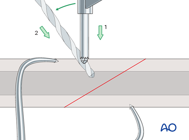
Countersinking
To reduce the high pressure of the hemispherical screw head contacting the flat cortical bone countersink the gliding hole. This distributes force over a greater contact area, helping to avoid microfracture.
This also results in the head of the screw being less prominent, which may be desirable in subcutaneous bone.
Determination of screw length
The depth of the hole is measured.
It is better for the hook on the depth gauge to catch on the longer side of the drill hole, as shown.
Alternatively, if it is not possible to engage the hook, measure the shorter side of the drill hole, but this will tend to underestimate the required screw length. The surgeon must make an allowance for this.
To ensure full thread purchase the tip of the screw should protrude 1–2 mm through the opposite cortex.

Insertion of non-self-tapping screws
TappingWhen non-self-tapping screws are used, tap both cortices.
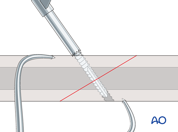
The screw is inserted at about 2/3 of the possible torque. Note that the screw protrudes 1–2 mm through the opposite cortex.
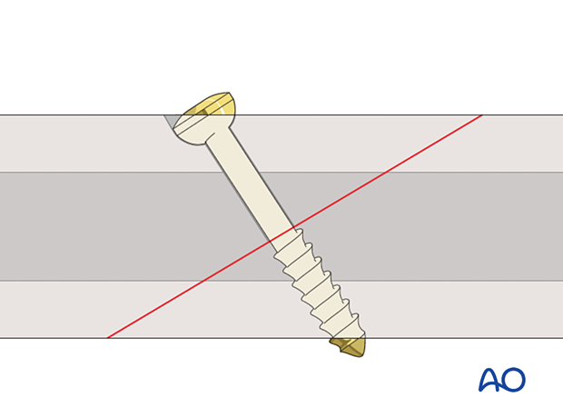
This 3D model shows the placement of a partially threaded cortical lag screw. In this case, a gliding hole is not needed.
Insertion of self-tapping screws
If self-tapping screws are used, tapping should be omitted, and the screw inserted directly.
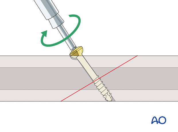
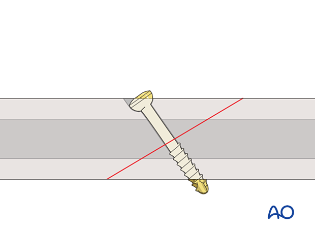
The tap portion of a self-tapping screw should lie outside of the screw hole when the screw is tightened, so a slightly longer screw is required.
However, too long a screw may cause soft-tissue irritation.
The screw is inserted at about 2/3 of the possible torque.
6. Lag screw with neutralization device
If the hold of lag screws alone is inadequate, a neutralization device such as a plate may be used to provide additional stabilization.
The plane of the fracture dictates the position of the lag screw. Anatomic considerations will influence the optimal positioning of the plate.
If the plate position and lag screw insertion site are aligned, the lag screw may be inserted through the plate.
The plate should be contoured and positioned appropriately. Then, with the fracture reduced, the lag screw is inserted through the plate first. The remaining screws are then inserted through the plate in neutral (not dynamic compression) mode.
If the location of the fracture plane makes it necessary to insert the lag screw from a position where it would be awkward to apply a plate, the lag screw should be inserted outside the plate, as shown in the illustration.
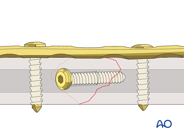
This 3D model shows a lag screw with a neutralization plate fixed in an orthogonal orientation to the screw.
By placing the neutralization plate in a plane rotated 90° to the plane of the lag screw, torsion and bending forces acting on the screw are reduced. The overall stability of the construct is increased.


