Screw insertion in compression mode
Introduction
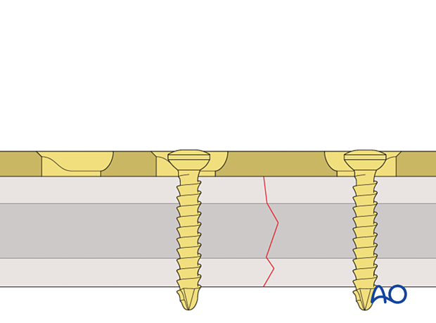
The principle of applying dynamic compression depends on relative movement between the bone and the plate as the screw is tightened.
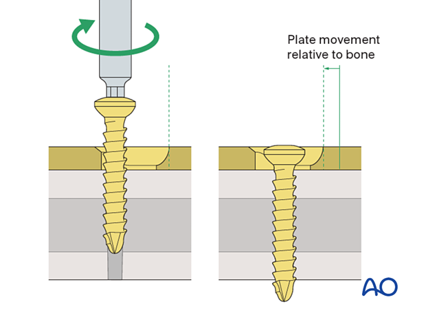
This 3D model shows relative movement between plate and bone
As the screw is advanced, the screw head engages on the sloping aspect of the plate combination hole and must displace the plate away from the fracture. Since the screw is fixed in the bone, the bone must also move in an opposite relation to the plate. As the screw is displaced towards the fracture gap by the plate the bone is also moved towards the fracture, thus obtaining contact and then compression of the bone fragments.
This 3D model shows screw insertion in compression mode with an overbent plate (Step 1)
To compress both the near and opposite (far) cortices, the plate should be slightly overbent before application, resulting in a convex shape, so there is a small gap between plate and bone at the fracture. Before the screws are inserted, the fracture is reduced. With the insertion of the first screw eccentrically in the screw hole, the overbent plate is pressed onto one bone fragment which causes slight displacement of the reduced fracture. The displaced fragment will be relocated with the insertion of the second screw in compression mode.
This 3D model shows screw insertion in compression mode with an overbent plate (Step 2)
The displaced fragment is reduced with the insertion of the second screw eccentrically in compression mode, straightening the plate and closing the gap at both near and far cortices.
Technique
For one-third tubular plates, the universal spring-loaded dynamic compression plate (DCP) drill guide is used without pressing it against the bone. The guide is placed against the edge of the plate hole, distal to the fracture.
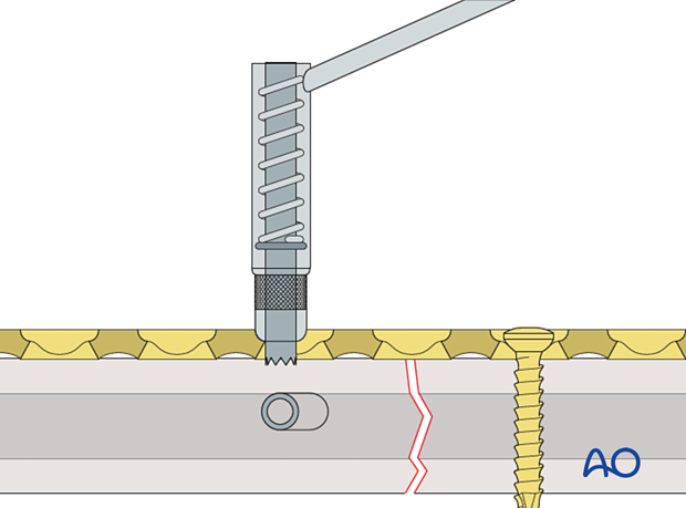
For dynamic compression plates with limited bone contact (LC-DCP plates), the DCP drill guide with a gold collar is used. The arrow on the drill guide should point in the direction of the fracture.
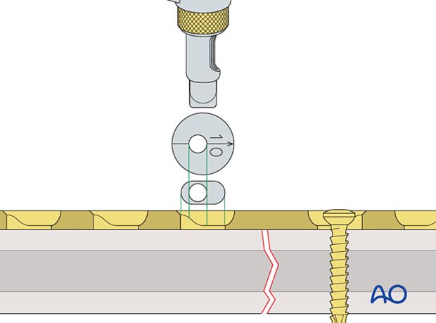
In locking compression plate (LCP) combi holes, the universal spring-loaded DCP drill guide can be used
without pressure against the bone in the non-threaded portion of the hole.
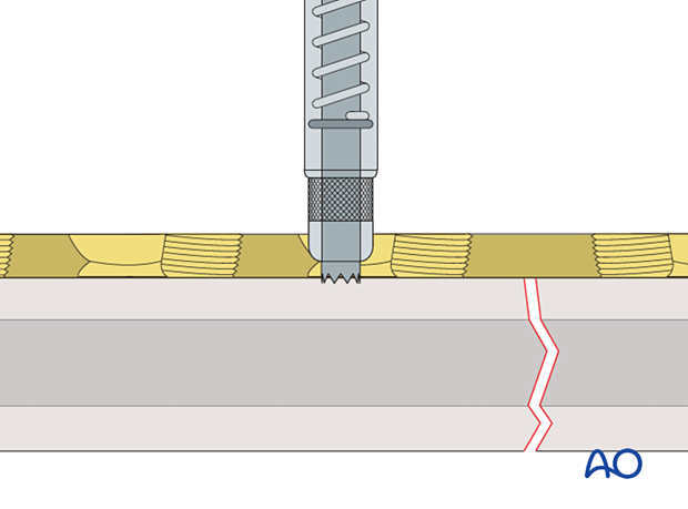
The hole is drilled through both cortices.
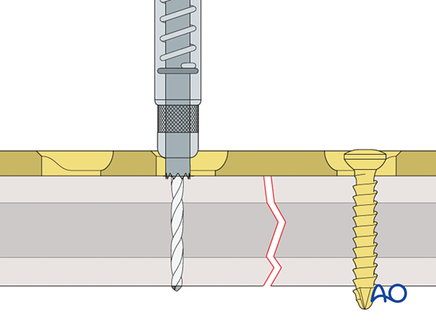
A depth gauge is used to determine the screw length.
If self-tapping screws are used add 2 mm to the screw length to make sure that the portion of the screw in the far cortex is fully threaded.
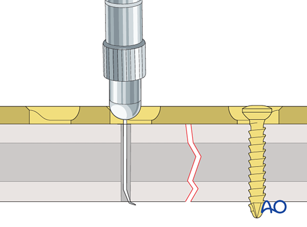
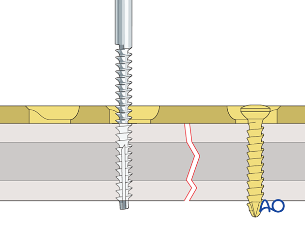
The hole is tapped.
If self-tapping screws are used, this step should be omitted.
As the screw is advanced the plate displaces in relation to the screw, moving the bone sideways with it in relation to the plate.
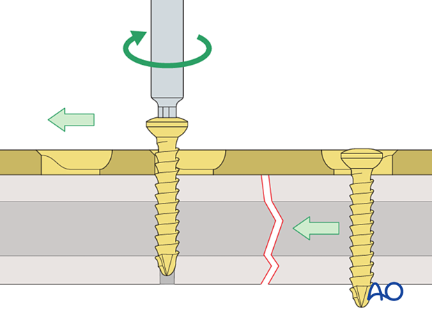
Once the screw is tightened, the fracture gap should be closed and compressed.
Teaching video
This technique can be used to treat transverse fractures and oblique fractures.
AO teaching video: Insertion of screw in compression mode for transverse fracture (application of compression plate)
Teaching video
AO teaching video: Insertion of screw in compression mode for oblique fracture (application of compression plate)


