ORIF - Lag screw and plate fixation
1. Principles
Options for fixation
For oblique forearm shaft fractures, interfragmentary compression can be achieved either by using an independent primary lag screw, protected by a plate (A), or by using a compression plate as the primary loading device with the addition of a subsequent lag screw through the plate (B).
Note: The first principle (A) will be described using two different techniques.Absolute stability
Absolute fracture stability, which is defined as the complete abolition of interfragmentary movement, is achieved by interfragmentary compression. It results in direct bone healing (in simple fracture configurations).
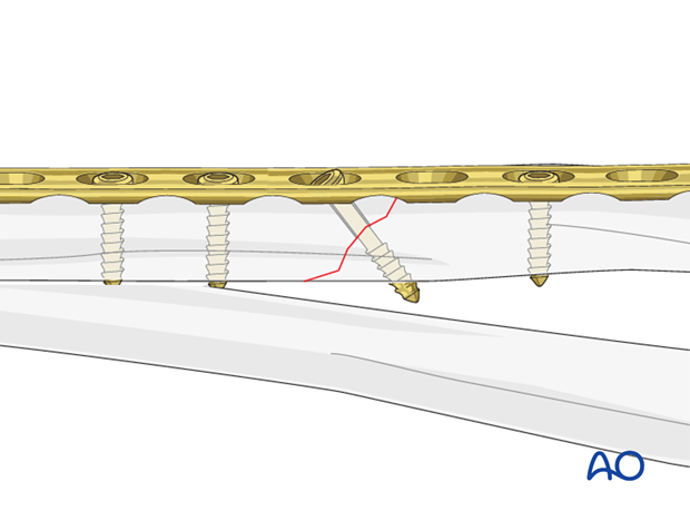
Interfragmentary compressionInterfragmentary compression can be achieved by a lag screw, inserted either through a plate hole (1), or separate from the plate (2).
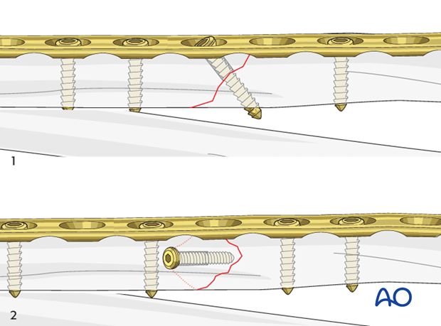
If available, a partially threaded cortical lag screw (shaft screw) can be used to accomplish interfragmentary compression.
Dynamic compression principle
The holes of the plate are shaped like an angled cylinder. The spherical undersurface of the screw head slides down the inclined cylinder as the screw is tightened.
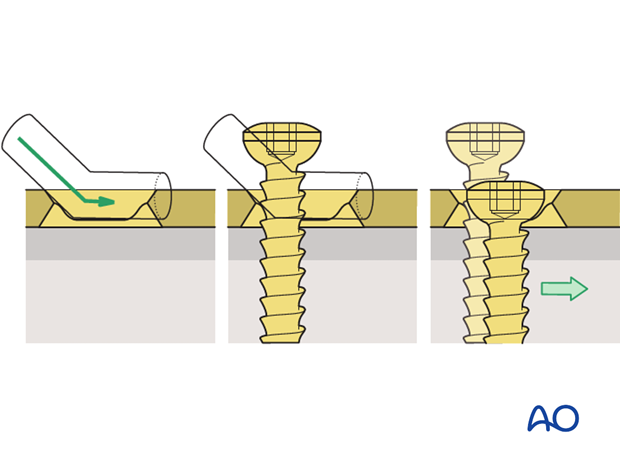
The horizontal movement of the head, as it impacts against the angled side of the hole, results in movement of the bone fragment relative to the plate, and leads to compression of the fracture.
Axial compressionInterfragmentary compression can be achieved by loading the oblique fracture site axially, using specific techniques.
Axial compression, using self-compressing plates (DCP, LC-DCP, LCP, etc.), is achieved by eccentric screw placement.

Plate position
Depending on the procedure chosen, the plate will be applied to either the anterior or posterior surface of the radius.
In the following example, we illustrate the plate applied to the posterior surface.
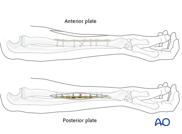
For proximal radial shaft fractures, the anterior approach (Henry) is most often used to minimize the risk of damage to the posterior interosseous nerve, which crosses the proximal radius within the supinator muscle.
In mid and distal radial shaft fractures, either the anterior approach (Henry) or posterolateral approach (Thompson) can be used, depending on surgeon’s preference.
2. Patient preparation
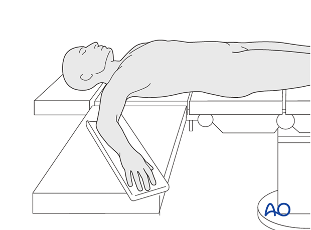
This procedure is normally performed with the patient in a supine position.
3. Reduction
Open and anatomical reduction
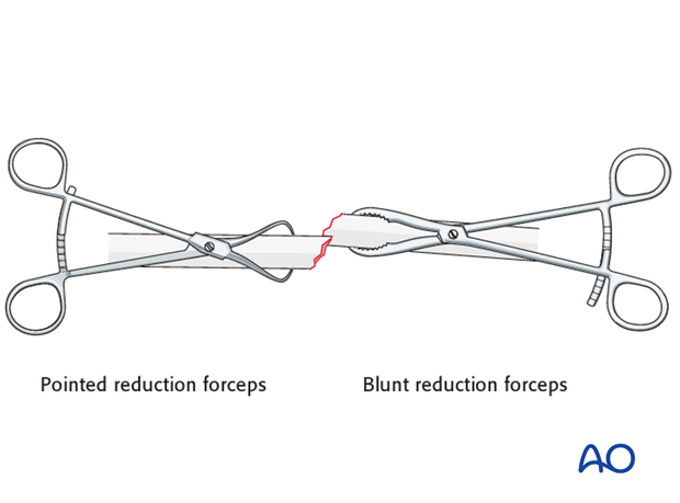
Reduce the fracture anatomically, using a reduction forceps on each main fragment. The use of blunt, as opposed to pointed, reduction forceps can be helpful, particularly if greater forces are required.
Pearl: leverage technique for oblique fractures
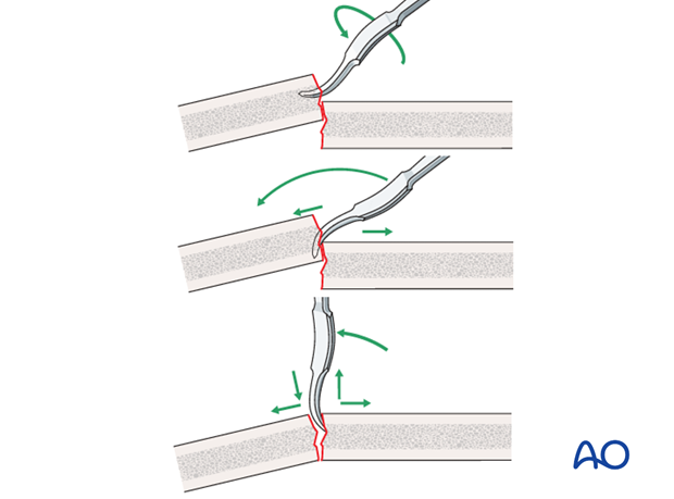
A small bone lever can be used to reduce the fragments.
Pearl: lengthening by twisting of reduction forceps
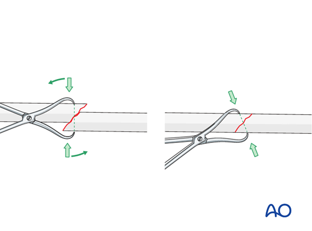
Reduction of overlapping oblique fractures can sometimes be achieved by twisting a reduction forceps, thereby lengthening the fracture.
Maintain fracture reduction
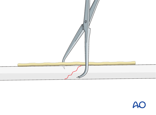
Maintain the fracture reduction with pointed reduction forceps. Place the forceps such that it will not interfere with the planned plate position.
4. Plate length and number of screws
In the forearm, in addition to any lag screw, three bicortical plate screws are required in each main fracture fragment due to the high torsional stresses. For biomechanical reasons, not every plate hole needs to be occupied by a screw. Therefore, plates with at least 8 or 9 holes are usually used.
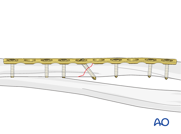
5. Fixation – lag screw as primary fixation device separate from plate
If the fracture morphology dictates that the interfragmentary lag screw be positioned separate from the plate, the plate then acts as a neutralization (protection) plate and axial compression should not be applied.
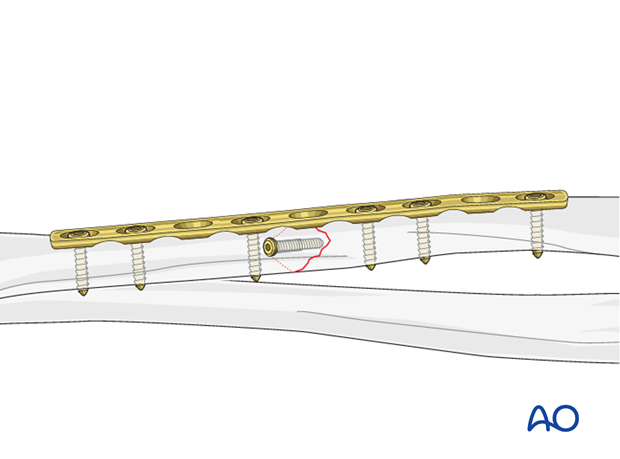
Drill gliding hole
Ensure that the direction of the drill is as perpendicular to the fracture plane as possible.

Thread hole: guide in gliding hole
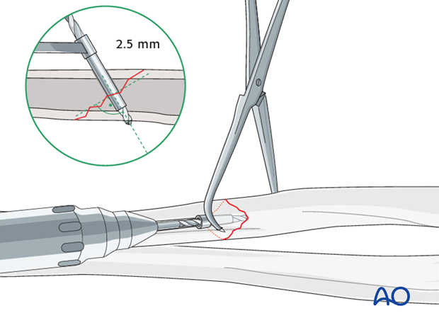
Insert the 3.5 mm / 2.5 mm drill guide into the gliding hole. Check that the anatomical reduction is maintained and use a 2.5 mm drill bit to drill a pilot hole just through the far cortex.
Measure for screw length
Use a depth gauge to measure for screw length.
Measure the longer side of the oblique drill hole, as shown, to ensure sufficient screw length.
The lag screw should protrude 1-2 mm through the opposite cortex to ensure maximal thread purchase. However, too long a screw may be tender, or injure soft tissues.
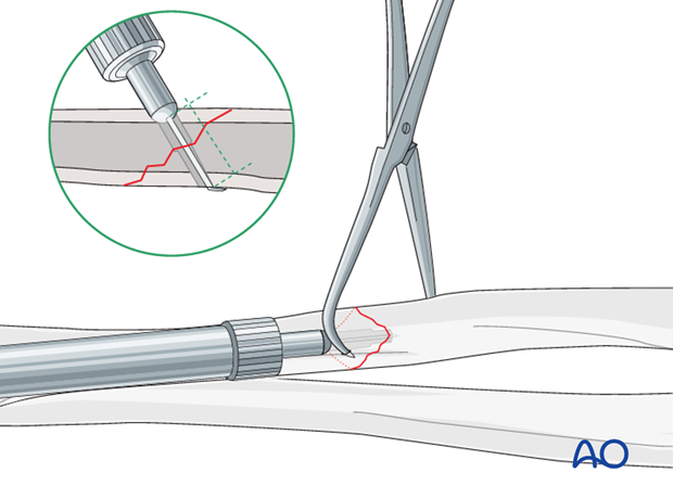
Tap the thread hole
This maneuver is not necessary when using self-tapping screws.
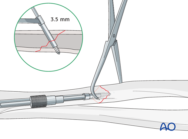
Lag screw insertion
Help to maintain the reduction by leaving the pointed reduction forceps in situ.
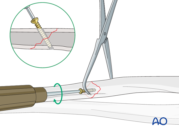
Neutralization (protection) plate
The pointed reduction forceps can then be removed.

6. Fixation – lag screw as primary fixation device through the plate
If this technique is used, then axial compression must not be applied via the plate.
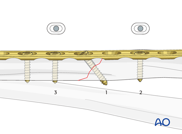
Drill gliding hole through plate
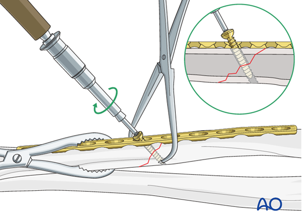
A perfectly contoured plate is now applied to the surface of the anatomically reduced fracture and fixed to one main fragment, either with a neutral screw, or with a bone forceps as illustrated. The interfragmentary lag screw can then be inserted through the appropriate plate hole.
Using a 3.5 mm drill sleeve and a 3.5 mm drill bit, drill a gliding hole in the near cortex.
Ensure that the direction of the drill is as perpendicular to the fracture plane as possible.
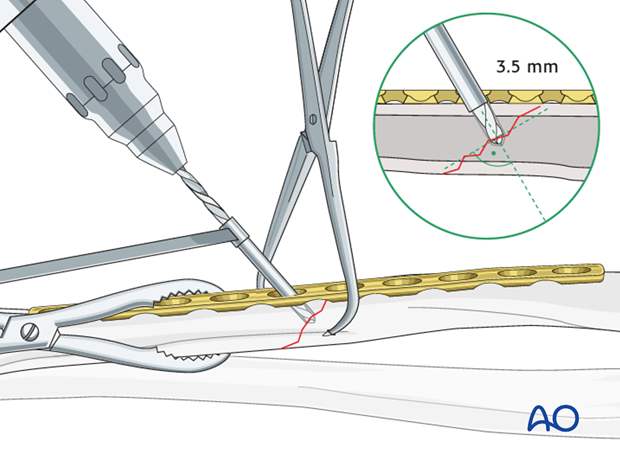
Thread hole: guide in gliding hole
Insert the sleeve of the 3.5 mm / 2.5 mm drill guide through the plate and into the gliding hole. Check that the anatomical reduction is maintained and use a 2.5 mm drill bit to drill a pilot hole just through the far cortex.
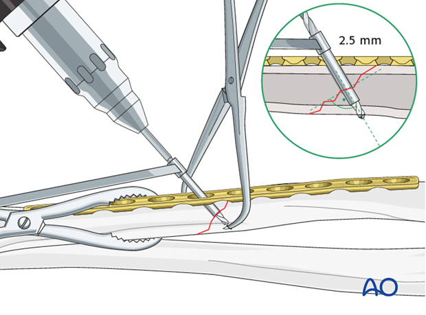
Measure for screw length
Measure the longer side of an oblique drill hole, as shown, to ensure sufficient screw length.
A screw should protrude 1-2 mm through the opposite cortex to ensure maximal thread purchase. However, too long a screw may be tender, or injure soft tissues.
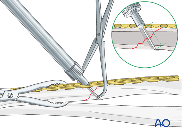
Tap the pilot hole
This maneuver is not necessary when using self-tapping screws.
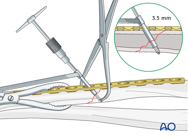
Lag screw insertion
Insert the lag screw through the plate and carefully tighten it, making sure that the fracture stays reduced, is compressed, and that the plate sits accurately on the bone surface.
Insert the plate screws
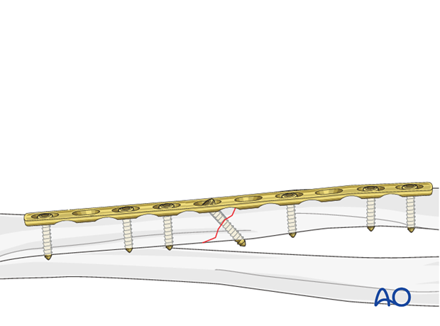
Complete the fixation by inserting the plate screws in neutral mode, usually alternately, in both main fragments.
7. Fixation – compression plating with an additional lag screw
Prebending the plate
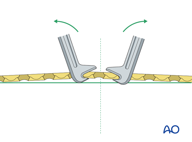
The solution to this problem is to “over-bend” the plate so that its centre stands off 1-2 mm from the anatomically reduced fracture surface.
When the neutral side of the plate is applied to the bone, slight gapping of the cortex will occur directly underneath the plate.
As the load screw is tightened, the tension generated in the plate compresses the fracture evenly across the full diameter of the bone.

Prebend the plate
After the plate has been contoured anatomically to the reduced bone surface, prebend the plate with the handheld bending pliers, or a pair of bending irons.
Insert 1st screw
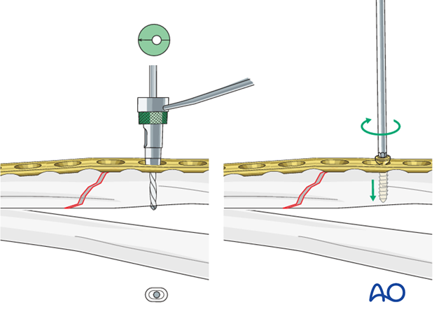
The aim of this maneuver is to create an “axilla” into which the other fragment can be compressed and locked either with a compression screw or using a push-pull technique.
Note: Because of the design of the LC-DCP holes, the neutral drill guides for the LC-DCP have a very slightly eccentric hole and an arrow, which needs always to point towards the fracture line.
Maintain reduction
A reduction forceps is placed on the opposite fragment to hold it in the reduced position against the plate.
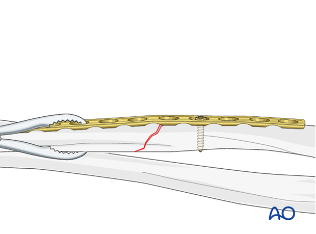
If reduction proves difficult, a bone spreader, placed between the end of a plate and an independent cortical screw, can be used to distract the fracture for reduction. Once reduced, the reduction forceps is tightened.
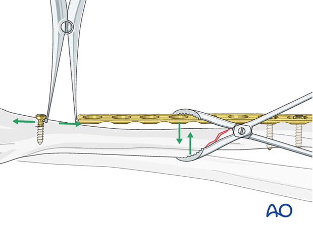
Then, using the same independent screw, axial compression can be obtained by pulling the plate end towards the screw with a small Verbrugge clamp.
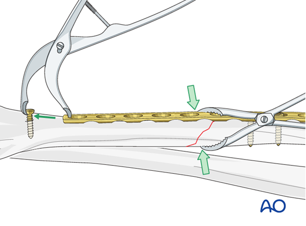
Insert 2nd screw eccentrically
Once reduced, a second screw is inserted eccentrically (yellow drill sleeve) into the reduced fragment.
Note: the arrow on the drill sleeve has to point towards the fracture line.
Tighten screw
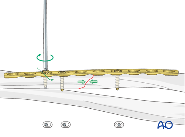
By tightening the eccentrically-inserted screw, axial compression is achieved.
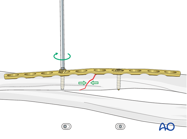
Insert additional screws
As the second eccentric screw is tightened, the first eccentric screw in the same fragment needs to be loosened slightly to allow the plate to slide on the bone.
Pearl: alternative drill sleeve
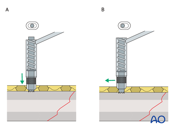
For inserting screws into the limited contact dynamic compression plate (LC-DCP), the Universal Drill Guide can be used as well. When this drill guide is pressed into the plate hole, the screw position will be neutral (A). When it is held against the end of the plate hole, without exerting downward pressure, the screw position will be eccentric (B).
Lag screw
The stability of a plate fixation in oblique fractures can be greatly increased by inserting a lag screw through the plate after primary axial compression has been achieved.
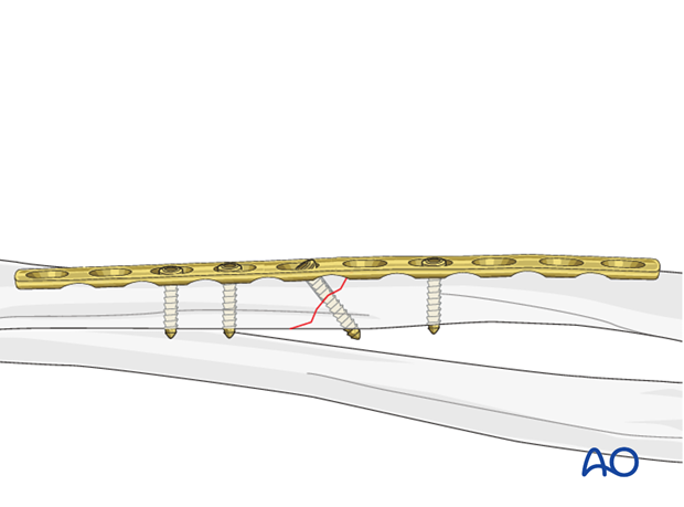
All other plate screws are now inserted in a neutral position (green drill sleeve) and do not serve further to increase compression.
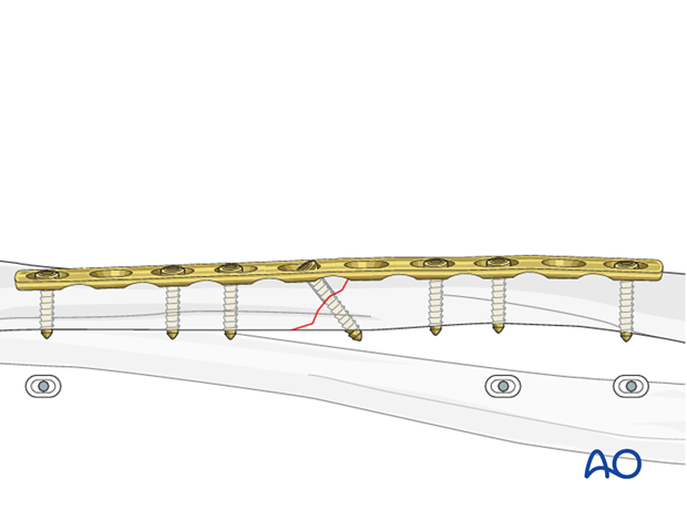
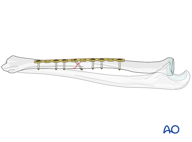
Completed osteosynthesis
This illustration shows the completed compression plate osteosynthesis of a oblique fracture with additional lag screw fixation.
8. Check of osteosynthesis
Check the completed osteosynthesis by image intensification. Make sure that the plate is at a proper location, the screws are of appropriate length and a desired reduction was achieved.
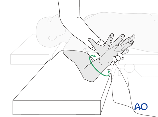
The elbow should be stabilized at the epicondyles and the forearm rotation should be checked between the radial and ulnar styloids.
9. Assessment of Distal Radioulnar Joint (DRUJ)
Before starting the operation the uninjured side should be tested as a reference for the injured side.
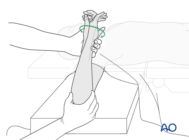
After fixation, the distal radioulnar joint should be assessed for forearm rotation, as well as for stability. The forearm should be rotated completely to make certain there is no anatomical block.
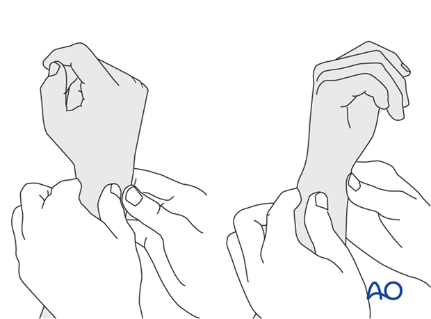
Method 1
The elbow is flexed 90° on the arm table and displacement in dorsal palmar direction is tested in a neutral rotation of the forearm with the wrist in neutral position.
This is repeated with the wrist in radial deviation, which stabilizes the DRUJ, if the ulnar collateral complex (TFCC) is not disrupted.
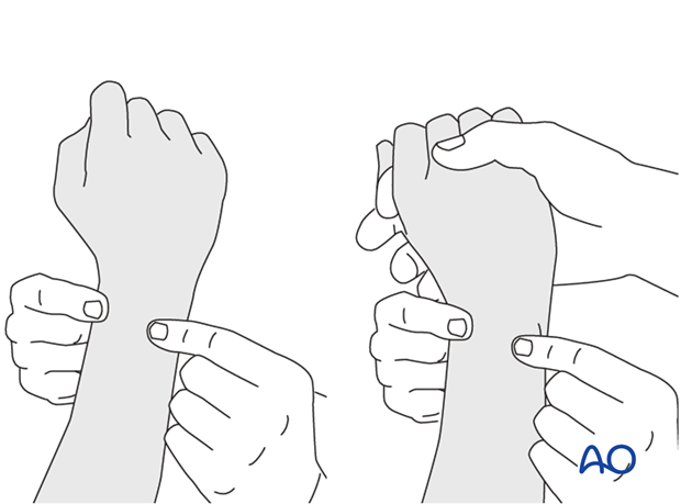
This is repeated with the wrist in full supination and full pronation.
Method 2
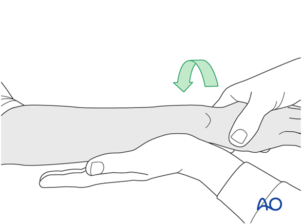
In order to test the stability of the distal radioulnar joint, the ulna is compressed against the radius...
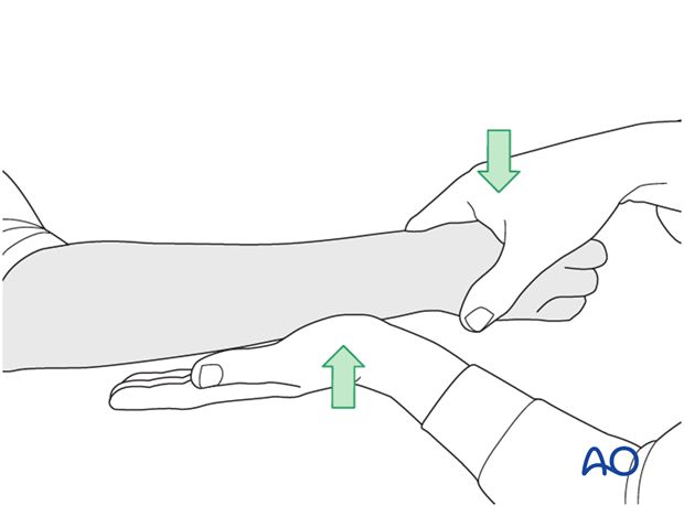
...while the forearm is passively put through full supination...
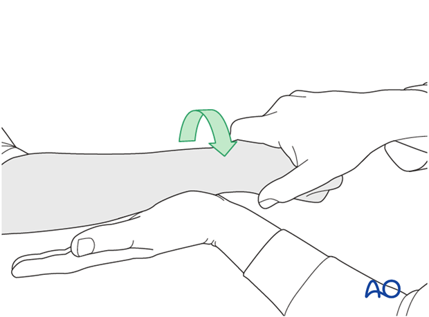
...and pronation.
If there is a palpable “clunk”, then instability of the distal radioulnar joint should be considered. This would be an indication for internal fixation of an ulnar styloid fracture at its base. If the fracture is at the tip of the ulnar styloid consider TFCC stabilization.
10. Postoperative treatment of a fracture treated with plating
Functional aftercare
Following stable fixation, postoperative treatment is usually functional.
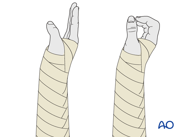
Immobilization in a circular cast may compromise the range of motion later. Temporary immobilization with a well-padded, bulky splint for 10-14 days is advised to allow adequate soft-tissue healing. During this period, elevation, gentle finger motion, active and passive, together with elbow flexion/extension and shoulder motion, can be started. The splint is then removed and active assisted range of motion exercises, including gentle forearm rotation, begin.
Lifting and resisted exercises are restricted until radiographic signs of healing appear. More intensive exercises, such as progressive resisted exercises can start thereafter. Timing of return to sport will depend on the individual patient and the nature of the sport.
Follow-up
Close postoperative follow-up is required in fractures that have been treated by means of absolute stability. Direct bone healing without callus formation is anticipated and early signs of instability with the presence of irritation callus should alert the surgeon to consider secondary interventions, such as restabilization and bone grafting.
Follow-up x-rays should be obtained according to local protocol. X-rays to assess fracture position are usually taken at 1, 2, and 4 weeks after operation. Subsequent x-rays are usually taken to assess bony healing at appropriate intervals from 6-8 weeks, depending on the fracture configuration and potential for healing.
Implant removal
In forearm shaft fractures, the issue of implant removal is controversial. As the radius and ulna are not weightbearing bones, and as removal of plates can be a demanding procedure, implant removal is not indicated as a routine. There is a high risk of nerve damage associated with procedures to remove forearm plates.
Furthermore, as there is significant risk of refracture, most surgeons prefer not to remove plates from the forearm.
The general guidelines today are:
- removal only in symptomatic patients, possibly only on the ulna where the implants are subcutaneous
- removal no earlier than 2 years after osteosynthesis
- If both bones have been plated, sequential removal of implants with a least 6 months in between is recommended (risk of refracture).
References
- Bednar DA, Grandwilewski W (1992) Complications of forearm-plate removal. Can J Surg; 35(4):428-431.
- Langkamer VG, Ackroyd CE (1990) Removal of forearm plates. A review of the complications. J Bone Joint Surg Br; 72(4):601-604.
- Rosson JW, Shearer JR (1991) Refracture after the removal of plates from the forearm. An avoidable complication. J Bone Joint Surg; 73(3): 415-417.
- Heim D, Capo JT (2007) Forearm, shaft. Rüedi TP, Buckley RE, Moran CG (eds), AO Principles of Fracture Management, Vol. 2. Stuttgart New York: Thieme-Verlag, 643-656.


