ORIF - Lag screw (epiphysis); MIO - Retrograde nailing
1. Principles
Introduction
Retrograde nail fixation relies on maintenance of the fracture viability in the metaphyseal / diaphyseal component of the fracture. This is made possible through closed reduction techniques and results in high union rates and low infection.
Malreductions (external rotation/valgus) can be common without careful scrutiny of intraoperative technique and radiographic control.
As this technique is indicated for complete articular fractures, it most important that the principle of perfect articular reductions is achieved before nailing is undertaken. The articular surface should be addressed by direct vision and standard interfragmentary compression. Careful insertion of the nail must ensure that the articular surface reconstruction is not disrupted. Retrograde nailing of in fractures with an injured articular block requires great surgical skill and experience, if disaster is to be avoided.
Use of additional plate fixation
Elderly, osteoporotic, and infirm patients need immediate immobilization. Often in this group of patients one fixation type does not provide enough stability for immediate mobilization. With this in mind, the fracture will require even more fixation than usual to ensure fracture stability until healing. Nail/plate constructs provide this stability in this group of patients. Nailing is usually performed first and supplemented with plates that are carefully fit around the nail using what cortical bone is available for fixation.

Reamed versus unreamed nailing
In general, reamed nailing allows the use of larger diameter implants and may therefore provide greater initial stability. It carries a greater risk of a large entry hole causing articular cartilage damage but reduces the risk of disruption of the fixation of the intraarticular component of complete articular fractures.
On the other hand, fat embolization is a concern and with the solid unreamed nails, the forces required to achieve nail torsion are higher. Most centers prefer reamed nailing as the standard procedure.
In elderly patients with osteoporotic femoral canals, no, or only minimal, reaming may be required because the canal is capacious and a very large diameter nail can be used.
Anatomy of the distal femur
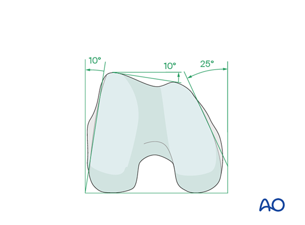
The distal femur has a unique anatomical shape. Seen from an end-on view, the lateral surface has a 10° inclination from the vertical, while the medial surface has a 20–25° slope.
A line is drawn from the anterior aspect of the lateral femoral condyle to the anterior aspect of the medial femoral condyle (patellofemoral inclination) that slopes approximately 10°. These anatomical details are important when inserting screws. In order to avoid joint penetration, these devices should be placed parallel to both the patellofemoral and femorotibial joints planes.
The muscle attachments to the distal femur are responsible for the typical displacement of the distal articular block following a supracondylar fracture, namely shortening with varus and extension deformity. Shortening is due to the pull of the quadriceps and hamstring muscles, while the varus and extension deformity is caused by the unopposed pull of the adductors and gastrocnemius, respectively.
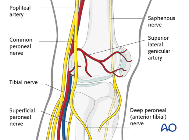
The popliteal vessels, the tibial nerve, and the common peroneal nerve lie near the posterior aspect of the distal femur. Because of this, vascular injuries occur in about 3% and nerve injuries in about 1% of fractures of the distal femur.
There are no significant arteries, veins, or nerves on the lateral side of the knee.
There may be bleeding from the lateral genicular arteries, which will need to be controlled using diathermy.
At the posterior aspect of the knee lie the popliteal artery, nerve, and vein. It must be borne in mind that these structures can be damaged by the injury or can be damaged by the surgeon during the reconstruction.
Teaching videos
This video demonstrates the insertion of the distal femoral nail (drylab)
This video demonstrates the insertion of the distal femoral nail (wetlab)
2. Patient preparation and surgical approach
Patient positioning
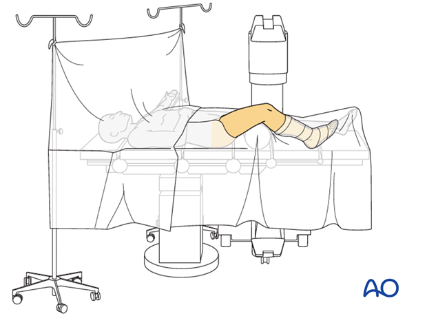
This procedure may be performed with the patient placed supine with the knee flexed 30°.
Surgical approach
The retrograde nailing approach is used.
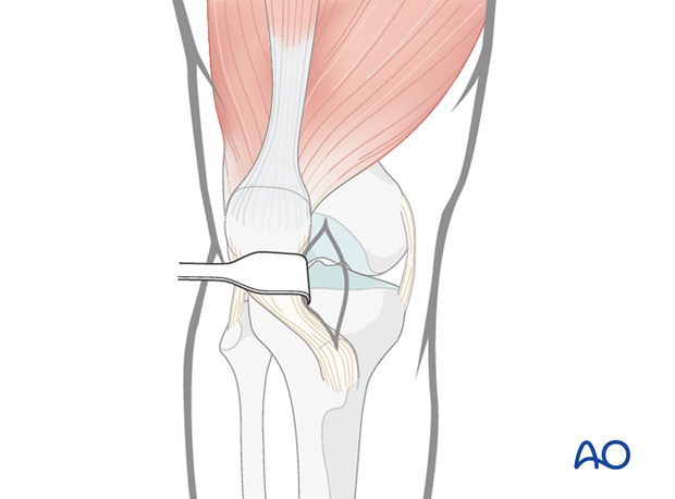
Surgical approach

3. Reconstruction of the articular block
Reduction of the articular block
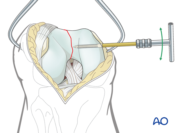
The approach must adequately expose the articular surface of the distal femoral condyle. Reduction aids that are helpful include:
- A 5.0 mm or 6.0 mm Schanz pin in the medial and/or lateral femoral condyle to act as a joystick.
- Pointed reduction forceps, or large pelvic reduction clamps, to clamp from medial to lateral across the intercondylar split.
Attempts at reduction of the intercondylar split with the pointed reduction forceps alone are often unsuccessful, as rotational control of the femoral condyle is also needed. The use of the Schanz pin in conjunction with the pointed reduction forceps is therefore preferred.
Provisional fixation
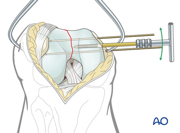
Before definitive fixation is undertaken, more than one clamp is applied. Usually, one to two additional K-wires are inserted, either from medial to lateral, or lateral to medial.
If the K-wires are inserted from medial to lateral, they may either go through small stab incisions in the skin, or through the parapatellar retinaculum.
Definite articular surface fixation
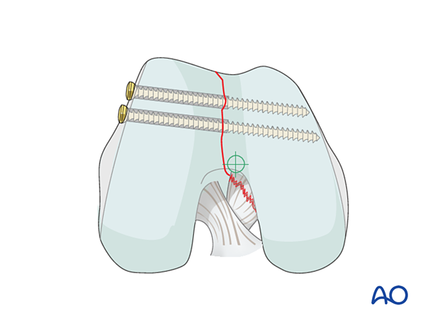
Lag screws are inserted along the periphery of the articular surface of the lateral femoral condyle, going from lateral to medial, in order to compress the intercondylar split.
These screws may be fully threaded 3.5 mm lag screws (with gliding holes, as shown), 6.5mm partially threaded lag screws, or 4.0/4.5 mm cannulated, partially threaded lag screws.
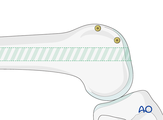
This end-on view demonstrates the screw trajectory from lateral to medial. Such screw placement allows for insertion of the retrograde nail, without implant conflict.
On occasion, it is acceptable to insert screws through the articular surface when no other options are available. These screws should be countersunk and recessed beneath the articular surface.
4. Preliminary reduction of metaphysis
Reduction techniques
A variety of techniques can be used to aid the reduction of the distal femur.
For most fractures, manual traction would be satisfactory. In some cases, more sophisticated reduction techniques must be used depending on the metaphyseal fracture configuration, such as:
- Schanz screw
- Bone hook
- Pointed reduction forceps
- Collinear clamp
- External fixator
Occasionally an open reduction is required, not just of the articular block but of the fracture itself, and of course, if this is performed, then stripping must be minimized.
Manual reduction
The fracture reduction may be achieved by longitudinal traction applied to the upper tibia.
It is useful to have a small sandbag just behind the hip joint to prevent external rotation. This will make subsequent alignment of the distal femoral condyles easier to orientate.
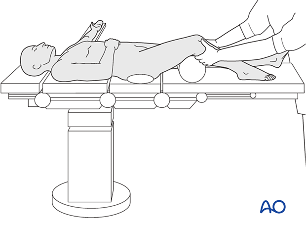
Muscle forces acting on the fracture fragments often determine the pattern of displacement of a fracture. Traction alone can restore the normal length of the bone, but may exaggerate the axial malalignment, instead of correcting it.
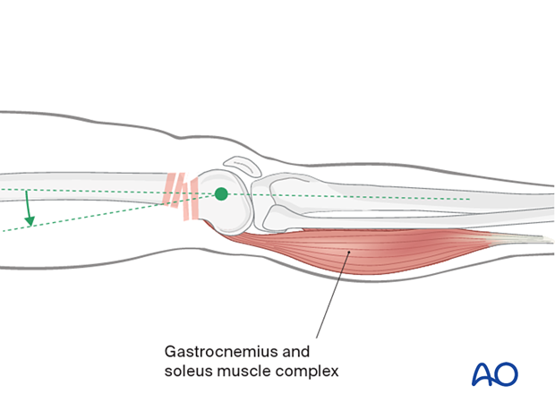
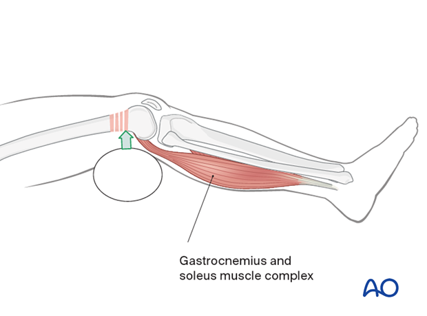
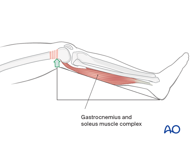
The distal femoral fracture can be reduced by flexing the knee to reduce the muscle force of the gastrocnemius muscle.
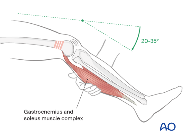
A supporting pad can be used to help to correct a recurvatum deformity. If this is not completely satisfactory, then percutaneous joysticks are used.
Alternatively, a carbon triangle can be used.
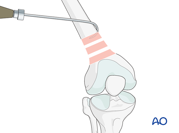
Bone hook
Direct reduction with a bone hook may be helpful in securing anatomical alignment. Careful insertion and manipulation must be performed in order to minimize soft-tissue trauma and to prevent injury to the femoral artery.
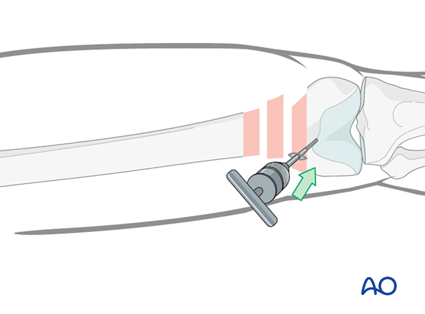
Collinear clamp
Depending on the fracture morphology, reduction of the distal femur can also be achieved using a collinear clamp.

Schanz screw/external fixator
One or more monocortical Schanz screws can be helpful for providing direct control of displaced main fragments. It is superior to external reduction maneuvers.
An external fixator can be installed according to standard procedure.
Verification of successful reduction
It is very important to restore the biomechanical axis of the lower limb. The normal biomechanical axis follows a line from the center of the femoral head, through the center of the proximal tibia and then through the center of the ankle joint. This axis can be checked intraoperatively by using a piece of cable, such as the diathermy cord. The cord is stretched from the iliac spine across the patella to the cleft between the first and second toes.
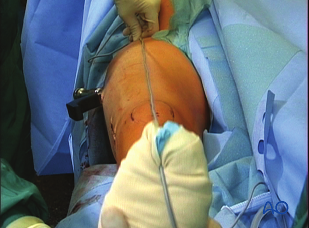
If rotation is correct, this cord will pass over the midline of the patella, and slightly medial to the tibial eminence. The radiological landmarks of the center of the femoral head, the center of the knee and the center of the ankle joint should all be in line if the mechanical axis of the femur is correct.
Another method of assessing rotational reduction is to compare the cortical thickness above and below the fracture. If a shaft fracture is multifragmentary, the image intensifier cannot be used to compare cortical diameters on each side of the fracture.
Not only must the biomechanical axis be restored, but care should be taken to ensure that there is no malrotation of the distal femur on the proximal femur.
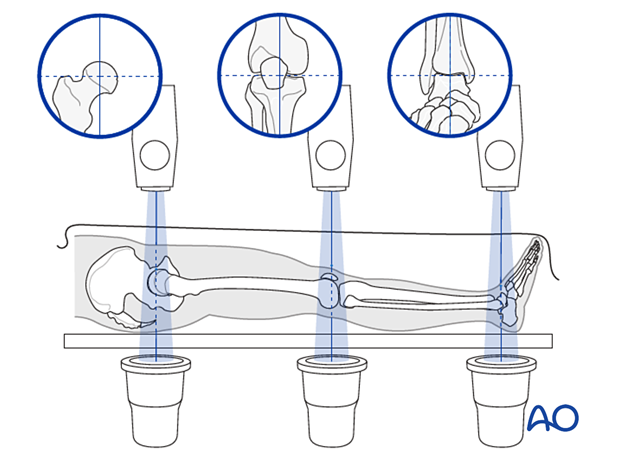
This illustration shows the longitudinal axes of the lower limb.
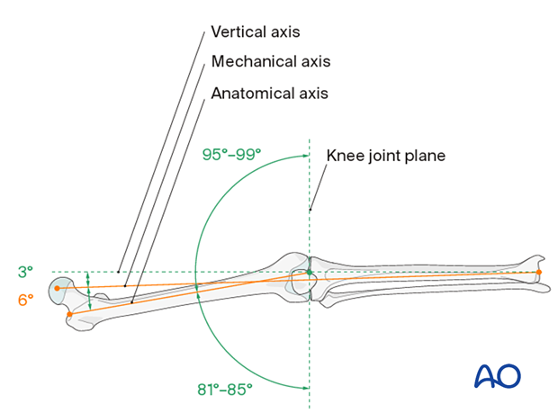
Confirmation of length
To ensure that femoral length has been restored, many options exist:
- One option involves reducing the fracture fragments anatomically, either directly or indirectly with fluoroscopic control.
- Even in multifragmentary fractures, there are usually a few main fracture segments that can assist the surgeon in ensuring that the appropriate length has been obtained.
- Another option involves taking radiographic images of the contralateral distal femur for comparison.
- A radiographic ruler can be used to measure the length of both femora. In this technique, it is important that the x-ray beams are perpendicular to the OR table and that the ruler is parallel to the OR table.
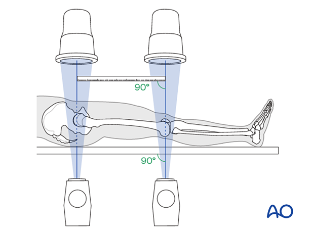
Poller screw
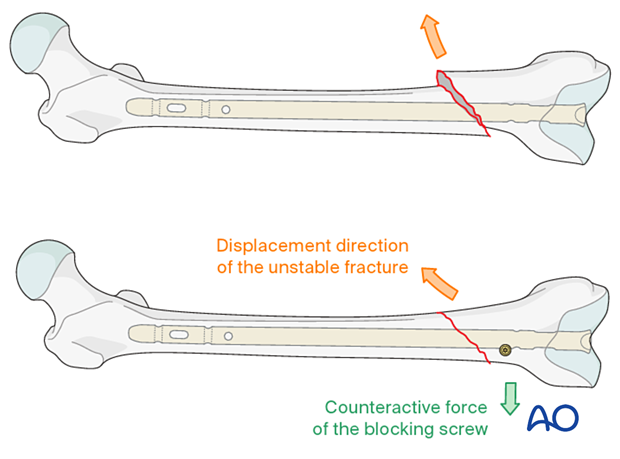
The concept of a poller screw is based on the principle that the malalignment induced by oblique, proximal and distal fractures can be counteracted by the nail-directing effect of the screw. Therefore, its position should aim to counteract the anticipated displacement of the fracture. Most often, it is therefore inserted in the short side in the distal fragment. If there is a wide canal, two screws can be inserted, one on either side of the path of the nail. It is technically challenging to insert the poller screw in the exactly correct position. On one hand, the screw should prevent reaming in the undesired location. On the other hand, it should not impede the reaming process, or nail insertion.
It is better to insert the poller screw prior to reaming and, in cases of unreamed nailing, prior to nail insertion, in order to provide adequate contact between the nail and the screw. If the poller screw is inserted after reaming, the path of the nail is already set and the poller screw may not function. A small fracture screw, or a locking screw, can be used as a poller screw, depending on the local anatomy.
The reaming process in the presence of the poller screw must be performed very carefully in order not to damage the reamer tip.
The most frequent indication for poller screws is an oblique fracture which would tend to shift when the axial knee blow technique is used to close any fracture gap, or when the patient is mobilized.
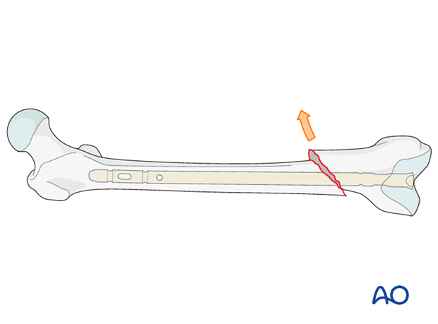
The poller screw should be located according to the direction of the initial fracture displacement. Therefore, with medial displacement, the fracture will try to displace medially even after the reduction and a poller should be placed lateral to the proposed nail track.
If there is a wide canal, or a very unstable situation, a blocking screw can be placed on each side of the proposed nail path.
5. Implant selection
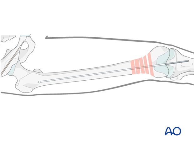
The guide wire is inserted into the predrilled entry portal. Advancement into the proximal main fragment is usually easier than in antegrade nailing and is performed under image intensifier guidance.
The guide wire is inserted up to the area of the lesser trochanter, where it will have good purchase and preventing movement during reamer exchange.
Nail length
Variations in surgical preferences exist regarding the optimal length of a retrograde nail for treatment of a distal femoral fracture.
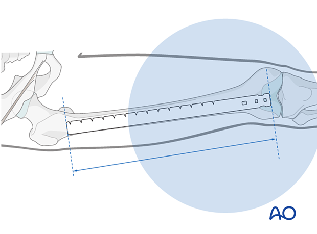
The retrograde nail usually should terminate at the level of the lesser trochanter. A nail that is any longer will create a stress riser at the level of the femoral neck. A nail that is any shorter will end in the diaphysis where locking is more difficult.
The maximal length of the nail is determined by comparing a second identical length guide wire to the one that has been inserted. The correct placement of the guide wire in the proximal canal should be assessed via image intensifier. Additionally, the second guide wire must be positioned in contact with the articular surface of the distal femur. This must be verified by image intensifier as well.
The distal end of the nail needs to be buried in the distal femur so that is not ever prominent. But, it must also be close enough to the surface so that it can be easily extracted if nail removal is necessary.
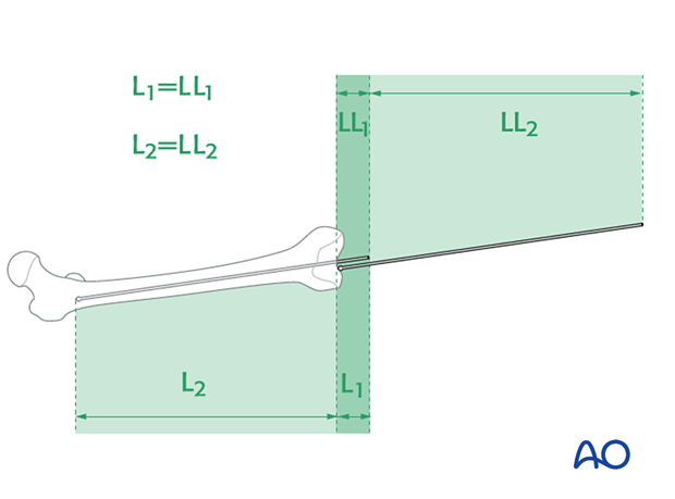
Alternatively, a radiographic ruler may also be used to determine the length of the femoral nail.
The ruler should lie in the center of the distal end of the femur at the roof of the intercondylar notch and along the center of the medullary canal.
It is important to visualize the fracture zone by image intensifier to carefully ensure that adequate femoral length has been maintained.
Nail diameter
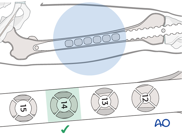
It is important to measure the medullary diameter at the mid portion of the femur, which represents the narrowest segment of the medullary canal (isthmus).
The inner cortical edge should touch the inner numbered disk of a ruler aperture. In the illustration an inner cortical diameter of 14 mm is shown.
Consideration for special situations
In multifragmentary fractures, or in open fractures with bone loss, it is safer to perform preoperative planning on the uninjured leg. In bilateral femoral fractures, the less comminuted side should be used to determine the length and diameter of the nail.
6. Reaming
Sequential reamer size increase
After the tissue protector has been introduced, the reamer shaft, fitted with the initial reamer head is inserted over the guide wire. Reaming begins with a nine-millimeter, end-cutting medullary reamer.
Sequential reaming is performed with increments of 0.5 mm each.
As soon as “chatter” can be felt and heard, the inner cortex has been reached. This may not be the case in segmental fractures, or when severe comminution is present.
Reaming must be performed to one or two increments above the planned nail diameter, in order to allow a smooth nail insertion. For example, for a nail diameter of 10 millimeters, reamer heads of up to 10.5, or 11, millimeters diameter are used. If a very tight fit of the reamer can be felt before the desired reaming size is reached, consider a smaller diameter nail than previously planned.

Pitfalls
- Eccentric reaming can cause weakening of the adjacent cortex, which may interfere with healing, or even cause a fatigue fracture.
- If the reamer gets trapped while reaming, it must be gently removed by the most senior surgeon because breakage of the reamer tip in this situation can be a devastating complication.
- Reaming with excessive force should be avoided because it is likely to cause heat necrosis of the femoral cortex. This applies especially for narrow midshaft canals (9 mm or less in diameter).
Rapid thrusting/systemic fat embolization
Care should be taken to use sharp reamers, to advance the reamers slowly, and to allow sufficient time between reaming steps for the intramedullary pressure to normalize. Rapid thrusting of the reamer may worsen the intramedullary pressure increase that is observed during nailing. This image demonstrates fat extrusion in a human cadaver specimen with a window in the proximal section.
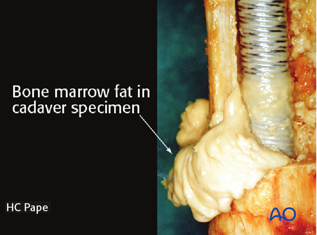
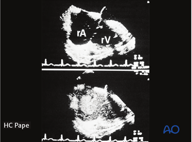
This may cause pulmonary embolization of medullary fat, which in turn may lead to pulmonary dysfunction (lower image in the enlarged view shows an example of fat embolization through the right atrium).
Conversion from an external fixator to an intramedullary nail
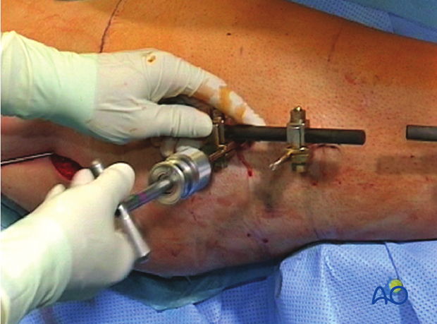
If an external fixator is in place, the Schanz screws must be partially withdrawn to allow the guide wire, the reamers, and later the nail, to pass through. The external fixator is held in place by monocortical purchase to assure that the fracture remains stable. The external fixator also acts as a joystick for the reduction.
7. Nail insertion
General considerations
During nail insertion, it is important that the assistant apply traction to the lower extremity, in order to prevent shortening and/or angulation of the distal main fragment. In order to prevent this complication, which is very difficult to correct later, repeated image intensifier assessments are required.
Nail insertion
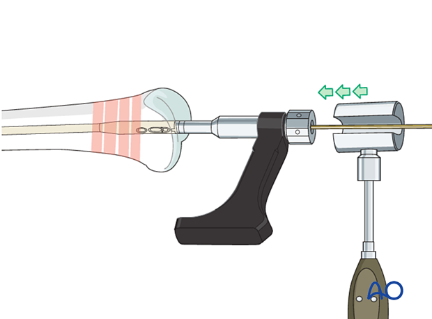
Drive the nail gently into the near fragment. This can often be performed manually. If required, gentle hammer taps are usually enough to ensure proper advancement. Insert the nail until it just passes deep to the cartilage surface.
Take care in osteoporotic oblique and multifragmentary distal femoral fractures not to shorten the femur by impacting the bone ends too firmly together.
Keep in mind the nail must be buried beneath the cartilage but not too deep to help in extraction if necessary after healing.
Also, the nail can distract the fracture site with impaction and this complication must be avoided. The backslap technique is necessary if the fracture gap is too large.
If the fracture is distracted, judging the distraction gap helps to determine how much deeper than usual the nail must be inserted. Proximal locking is performed first with 2–3 screws, and the nail is pulled back with gentle hammer blows until fracture contact is achieved (see “Backslap technique”). Recheck the distal end of the nail, which should not protrude distally.
8. Distal locking options
If the reduction is appropriate (length) it is important to perform the distal locking first. If proximal locking is done first, the surgeon will no longer be able to perform final corrections to length alignment or rotation.
In an uninjured articular block, a spiral blade can be used in addition to or instead of screws.
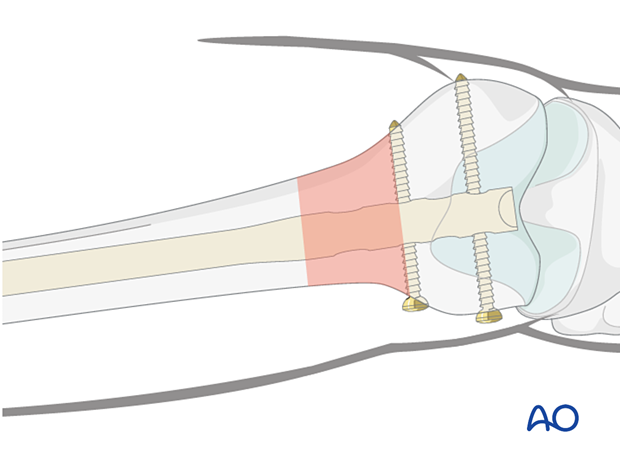
It is preferable to use at least two distal locking options for all distal femoral fracture types. When two distal locking options are used it is not possible to perform dynamic distal locking. Dynamic locking can only be achieved by using the proximal dynamic locking hole.
Dynamic or static locking
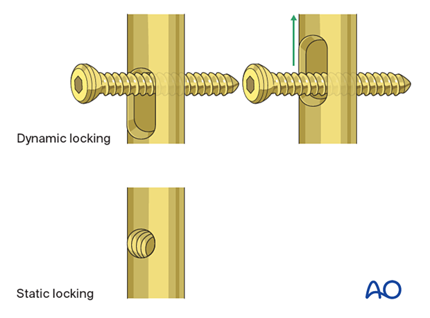
Simple transverse non-comminuted fractures are stable and fracture healing may be enhanced by dynamic locking. Comminuted fractures require a length stable construct so stable locking is mandatory. Slotted locking holes can be used for dynamic locking while small circular holes are used for static locking.
9. Distal locking with screws
Distal aiming device
After verifying the correct position of the distal end of the nail under image intensifier control, the distal aiming device may be attached to the insertion handle.
Pearl: Insert a guide wire through the small hole of the aiming device to determine the position of the nail end.
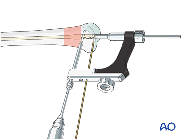
For correct measurements of locking screw length, the drill sleeve must be pressed onto the bone surface at all times.
Gentle pressure can be applied to the tip of the drill sleeve to maintain its correct position.
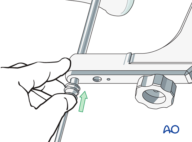
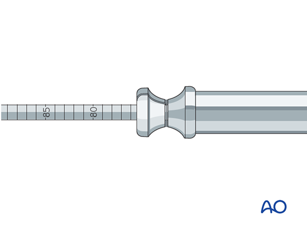
Screw insertion
The sites of the skin and fascial incisions for the drill bit and the distal locking screws may be determined after the drill sleeve assembly has been inserted into the holes of the aiming device. The length of each locking screw is read from the calibrated drill bit. The correct length is confirmed using image intensifier control.
Verification of locking screw placement
In all cases, obtain final x-rays in two planes in order to check the exact locking screw placement. If the normal tight coupling between the nail and the insertion guide has been altered, the screws might have been placed either anterior or posterior to the nail.
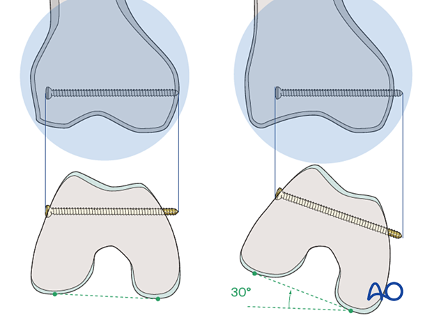
Pitfall: It is important to remember that the distal femur tapers from the posterior to the anterior. Therefore, if a straight AP view is obtained, the locking screws appear to be inside the bone. If they appear to be outside the bone, they are most likely too long and will invariably cause pain and possibly heterotopic ossification. In order to assess the exact length of the locking screws an AP view can be obtained with 30° internal rotation of the lower extremity.
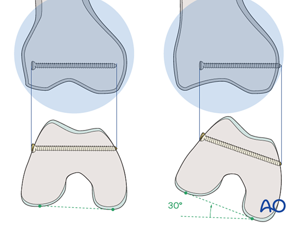
Internal rotation by 30° reveals that an inappropriate screw length was chosen.
10. Distal locking with spiral blade
Spiral blade
The spiral blade can be used with the retrograde femoral nail. The spiral blade can be locked as an angular stable implant. This will give rigidity to the fixation construct by virtue of increased surface area of the spiral blade.
The spiral blade is particularly useful in osteoporotic bone.
Additional locking screws may still be used with the spiral blade.
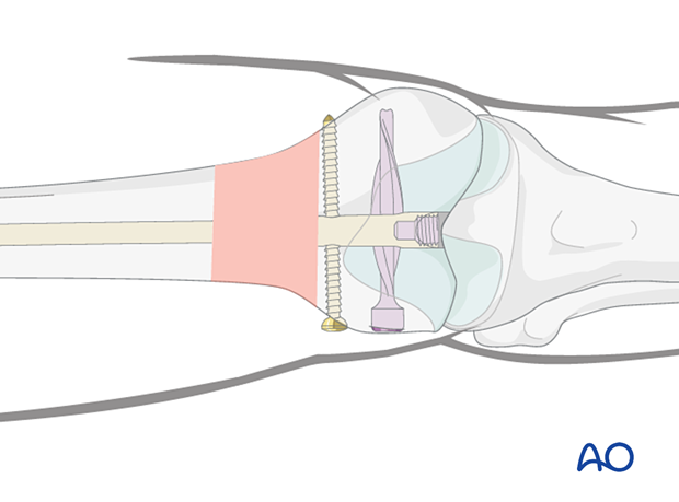
Principles of spiral blade insertion
It is important to confirm fracture reduction with AP and lateral intensifier images.
The aiming arm for the retrograde spiral locking blade is attached to the standard insertion handle.
The proximal locking screw must have been inserted before the spiral blade.
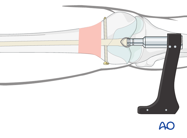
Applying the spiral blade jig
Make an incision through the skin to allow the spiral blade locking sleeve to be inserted through the jig and pushed down onto the bone.
Insert a 3.2 mm guide wire through the 13 mm/3.2 mm wire guide into the femoral condyles until the tip is flush with the medial cortex. Confirm wire position by x-ray, bearing in mind the trapezoidal cross section of the distal femur at this level.
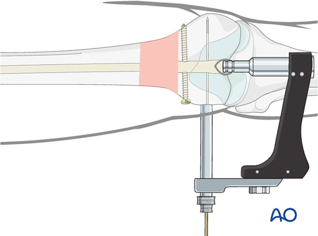
Insert guide wire and measure for spiral blade
Remove the 13.0 mm/3.2 mm wire guide. Place the spiral blade measuring device over the guide wire and advance it to the bone. Read the number on the measuring device at the end of the guide wire. This measurement is the length of the spiral blade.
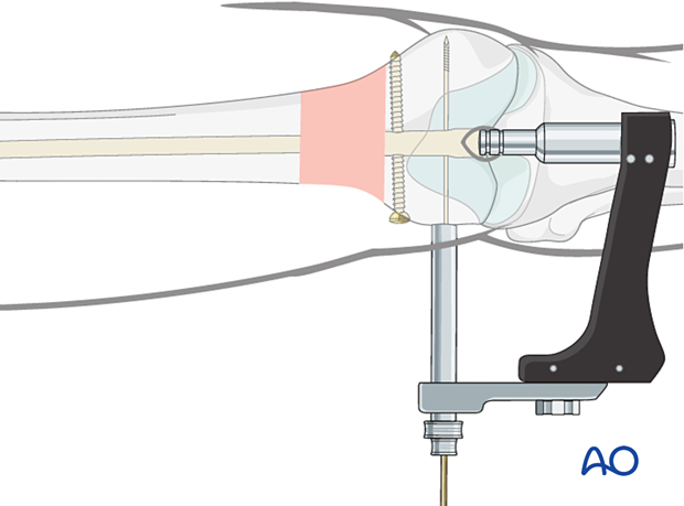
Open the lateral cortex
Insert the 13.0 mm cannulated drill bit over the guide wire and through the protection sleeve to perforate the lateral cortex. An automatic stop prevents the drill bit from penetrating too far. Remove the drill bit and protection sleeve.
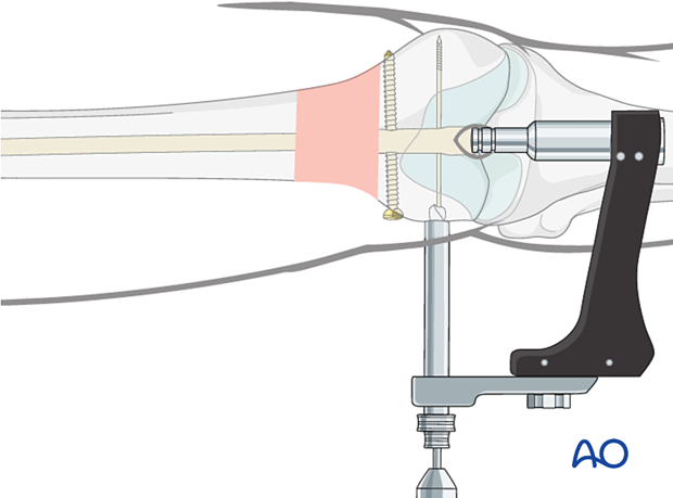
Insert the spiral blade
Attach the appropriate length spiral blade to the spiral blade inserter.
Pass the spiral blade assembly over the guide wire. Advance the spiral blade inserter through the aiming arm, ensuring engagement of the inserter’s helical grooves with the mating pins of the aiming arm. Manually advance the spiral blade to the bone. Use light, controlled blows of the slide hammer to seat the spiral blade. Advancement should be monitored radiographically. The correct insertion depth is reached when the spiral blade head is flush with the lateral cortex.
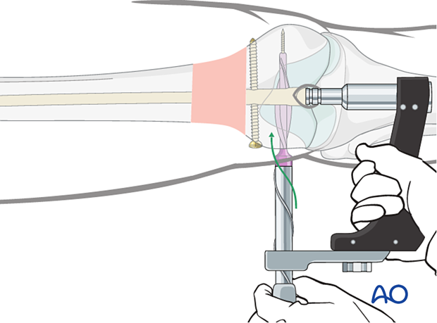
11. Intraoperative radiological assessment
Assessment of rotation
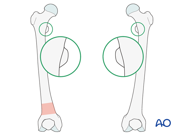
Compare the profile of the lesser trochanter with that of the contralateral leg (lesser trochanter shape sign), holding the leg so that the patella faces anteriorly on both sides.
Before positioning the patient, store the profile of the lesser trochanter of the intact opposite leg (patella facing anteriorly) in the image intensifier.
The illustration shows the lesser trochanteric profile of the intact opposite side.
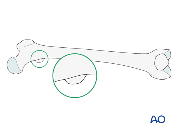
Malrotation
In cases of malrotation, the lesser trochanter is of a different profile when compared to that of the contralateral leg.
Take care to assess rotation with the patella facing directly anteriorly.
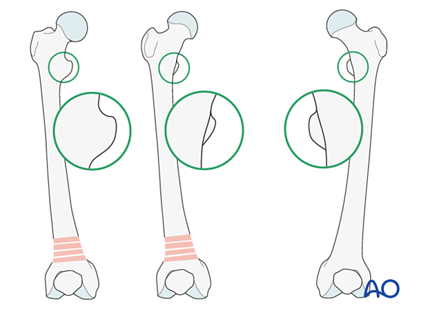
Matching of the lesser trochanter shape
After securing the plate to the distal femur, correct any malrotation by rotating the distal femur. Ensure that the profiles of the lesser trochanters are matched.
12. Proximal locking
General consideration
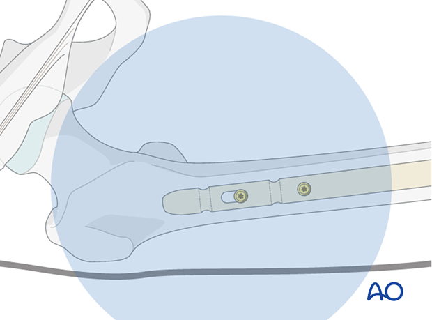
The first proximal locking screw is inserted in the anteroposterior plane. A radiolucent x-ray table is essential. Care must be taken in preoperative planning so that adequate image intensifier views of the proximal femur can be obtained in both the AP and the lateral planes before the operation begins.
The thickness of the subcutaneous tissue, especially in obese patients, can make this procedure technically demanding.
It is extremely difficult to perform lateral to medial proximal locking with a long retrograde femoral nail. This is due to the difficulty in positioning the image intensifier around the proximal femur.
Drilling of screw hole
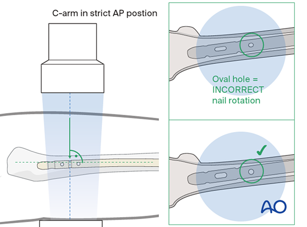
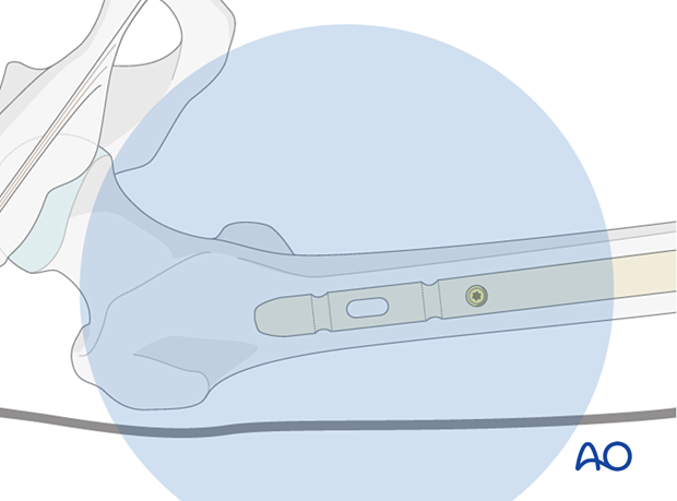
Proximal AP locking must be performed by the freehand method. After you have verified the correct position of the distal end of the nail under the image intensifier, visualize the shape of the proximal locking hole.
Then, bring the image intensifier into a strict AP position at 90° to the nail. The proximal static holes must project a perfect circle and the tip of a scalpel is projected into the center of the hole.
Make a skin incision and bluntly dissect the muscle.
Place the radiographic projection of the tip of the drill bit as centered as possible into the hole image. Start drilling but assess the position of the tip of the drill bit repeatedly, with the drill temporarily uncoupled.
While drilling the locking hole, the assisting surgeon must prevent the leg from moving, in order not to miss the target hole. This also ensures the leg is not malrotated.
Pearl: radiolucent drill
If available, a radiolucent angled drill can be used as described in distal locking of antegrade nailing for femoral shaft fractures.
Screw insertion
Determine the appropriate screw length with a depth gauge and insert the AP locking screw. Take care to prevent the oblique insertion of a locking screw because it can become trapped between the firm cortex of the proximal femur and the nail.
Second locking screw
Depending on the fracture pattern, use either one or two proximal locking screws.
The question as to whether a second locking screw in the long nail should be used must be decided by the surgeon on a case-to-case basis.
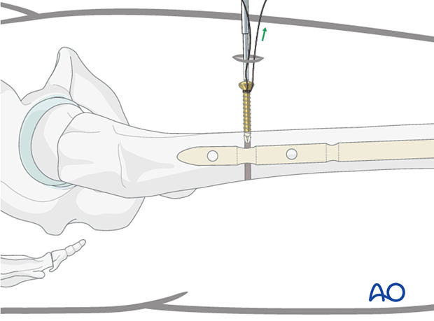
Pearl: If the contact between the screw driver and the locking screw is lost, the screw may move within the soft tissue and become extremely hard to capture. To prevent this time-consuming complication, lasso the locking screw with a strong absorbable suture.
13. Insertion of end cap
Insertion of the end cap with double screw distal locking
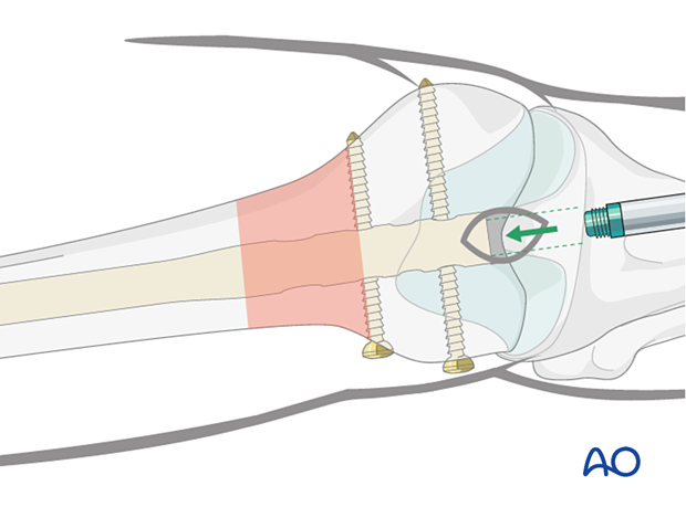
The use of an end cap will prevent ingrowth into the nail and facilitate later nail removal. The length of the head of the end cap depends on the final relationship of the nail end to the intercondylar notch of the distal femur.
In distal femoral fractures, the nail just passes the condylar surface resulting in the need for a 0 mm end cap. By no means should the end cap project distal to the subchondral region.
Introduce the end cap using a hexagonal screwdriver.
Insertion of the end cap with spiral blade locking
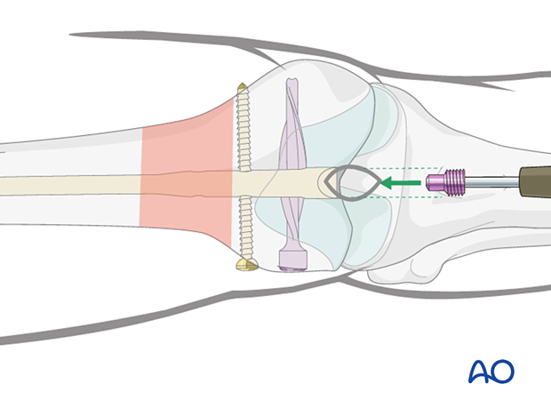
It is very important to secure the spiral blade with the dedicated end cap to create a fixed-angled device.
The end cap fulfills two functions: it prevents bony ingrowth into the nail and it locks the spiral blade, providing a stable, fixed-angle construct.
To minimize the chance of cross threading, turn the end cap counterclockwise until the threads of the end cap align with the threads of the nail. Insert the end cap by turning clockwise until it is fully seated.
Note: there is a difference in end-cap design. Use the color-coded end cap for the spiral blade.
Verification of end cap placement
Tighten the end cap with the screw driver. Verify using image intensifier control and palpation that the end cap has been fully inserted into the nail and does not project from the bone.

14. Optional – Plate insertion
Because the nail takes up the space in the intramedullary canal, only the cortical bone in the periphery is available for fixation.
In very unstable distal femoral end segments, it may be necessary to supplement retrograde nailing with other forms of fixation to provide more stability. Plates, allograft struts, or even intermedullary plates have been used to create more stability.
Each fracture is different but generally small fragment fixation with many options for carefully directed screws will supplement the intramedullary nail.
The plates that are used include semitubular, 1/3 tubular, LC-DCP, and LCP's. Usually, failure will occur in the distal femur on the medial (varus) side. This means plate placement is usually on the medial side of the femur where plate contouring may be necessary.
A medial plate is applied through a medial approach to the distal femur according the standard principles.
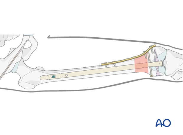
A lateral plate can also be applied but usually failure is expected into varus and so lateral plating is less commonly employed.
Each circumstance around fracture care is individualized. The nail that will be used in patients such as these will be large in diameter which will not leave much room for screw fixation.
The plate that is chosen should be of sufficient length to provide at least three bicortical points of fixation proximally and as much cancellous fixation distally as possible.
Some surgeons have used intramedullary allografts or plates to provide even stronger biomechanical constructs.

15. Wound closure, assessment of alignment and knee stability
Wound closure
End the procedure with the closure of the tendon (as necessary), the deep tissues and the skin.
Assessment of alignment
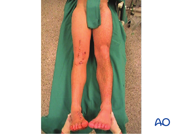
Before the patient is moved from the fracture table, rotation of the leg is observed clinically and compared to the contralateral leg.
With the femur now stable, it is possible to perform a thorough examination of the knee joint to rule out additional ligamentous injuries.
16. Aftercare
Impediments to the restoration of full knee function after distal femoral fracture are fibrosis and adhesion of injured soft tissues around the metaphyseal fracture zone, joint capsular scarring, intra-articular adhesions, and muscle weakness.
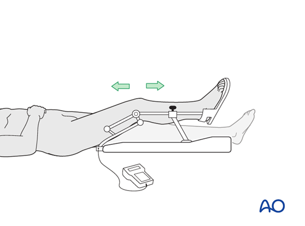
Early range of motion helps restore movement in the early postoperative phase. With stable fracture fixation, the surgeon and the physical therapy staff will design an individual program of progressive rehabilitation for each patient.
The regimens suggested here are for guidance only and not to be regarded as prescriptive.
Functional treatment
Unless there are other injuries or complications, knee mobilization may be started immediately postoperatively. Both active and passive motion of the knee and hip can be initiated immediately postoperatively. Emphasis should be placed on progressive quadriceps strengthening and straight leg raises. Static cycling without load, as well as firm passive range of motion exercises of the knee, allow the patient to regain optimal range of motion.
Weight bearing
Full weight bearing can be started immediately with range of motion.
Follow-up
Wound healing should be assessed at two to three weeks postoperatively. Subsequently 6-week, 12-week, 6-month, and 12-month follow-ups are usually made. Serial x-rays allow the surgeon to assess the healing of the fracture.
Implant removal
Implant removal is not essential but should be discussed with the patient if there are implant-related symptoms after consolidated fracture healing.
Thrombo-embolic prophylaxis
Thrombo-prophylaxis should be given according to local treatment guidelines.
