Locked intramedullary nailing (ALFN)
1. General considerations
Introduction
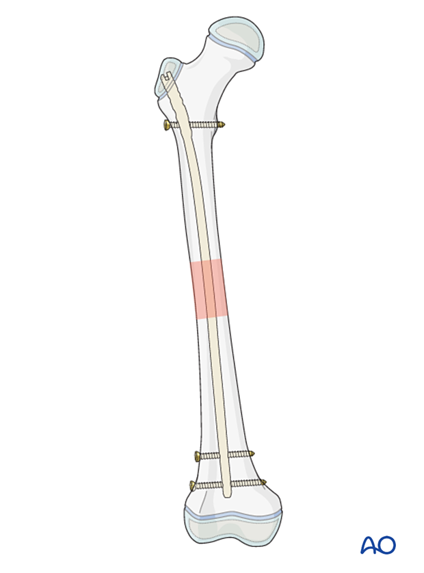
These nails are designed to enter through the lateral aspect of the greater trochanter and not through the piriformis fossa or trochanteric tip. The lateral entry approach decreases the chance of damage to the blood supply of the femoral epiphysis (see neurovascular anatomy).
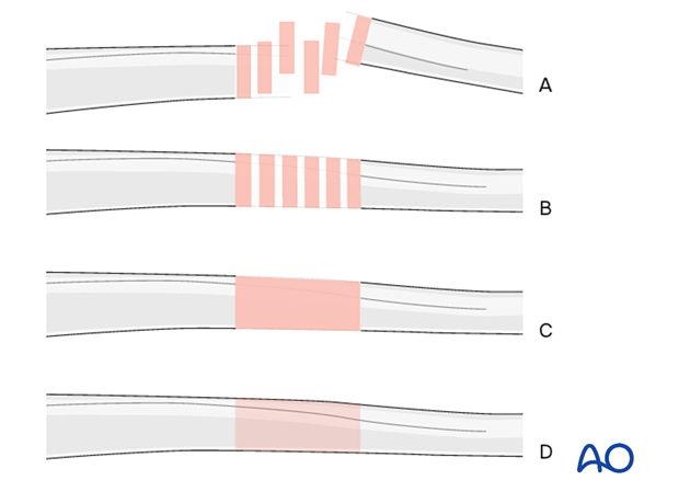
Throughout this section generic fracture patterns are illustrated as:
- Unreduced
- Reduced
- Reduced and provisionally stabilized
- Definitively stabilized
2. Instruments and implants
Equipment
- Pediatric nailing set
- Reamer set
For advice on specific nail types consult the relevant surgical technique guide.
Determination of nail diameter
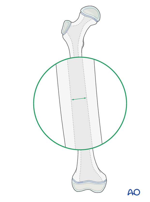
Young adolescents may have very thick cortex and narrow medullary canal. It is therefore important to carefully select the nail diameter.
Use pre- or intraoperative x-rays to determine the narrowest point of the medullary canal from the AP and lateral views and therefore the nail diameter.
Alternatively, select the appropriate diameter after sequential reaming of the canal.
Determination of nail length
Estimate the correct nail length from the preoperative x-ray. An x-ray of the contralateral side may be needed.
3. Patient preparation and approaches
Patient positioning
Place the patient either in a lateral decubitus or supine position on a traction table or radiolucent fracture table.
Approaches
The nail entry point lies on the lateral surface of the greater trochanter.

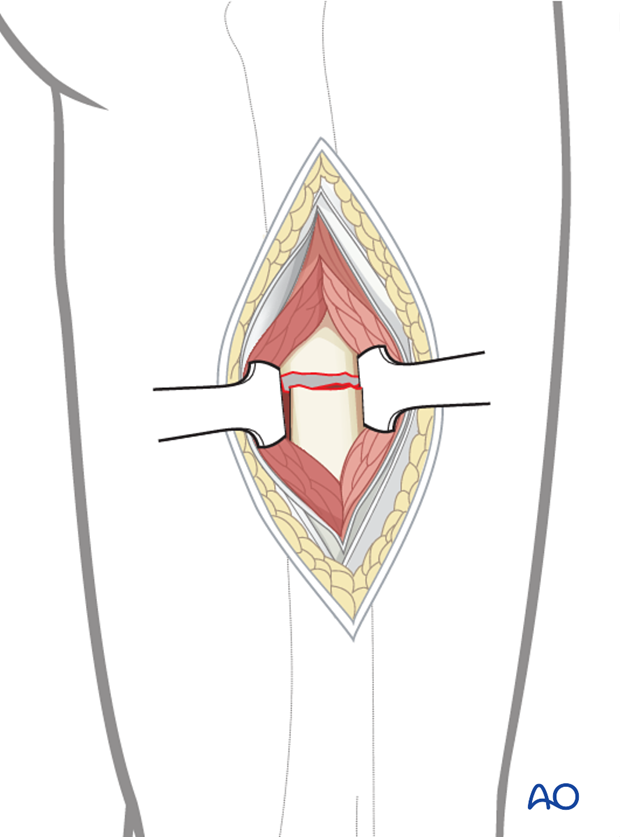
For open reduction a limited lateral approach may be necessary to access the fracture zone.
4. Insertion of guide pin
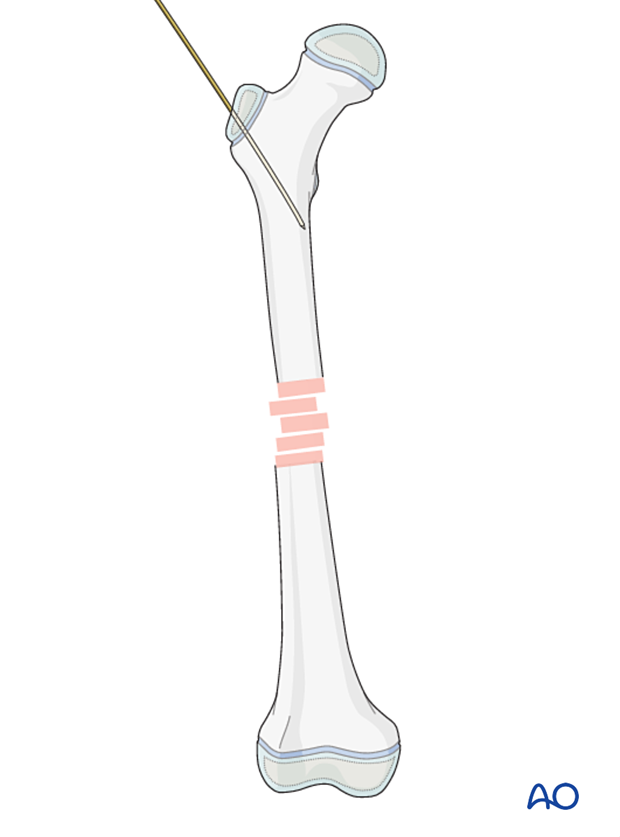
On the AP view the entry point is on the lateral aspect of the trochanter, one-third to one-half way down.
Insert the guide pin into the proximal femur at an angle to the femoral shaft.
This guide pin should stop 2 cm distal to the lesser trochanter and in the center of the medullary canal on the lateral view.
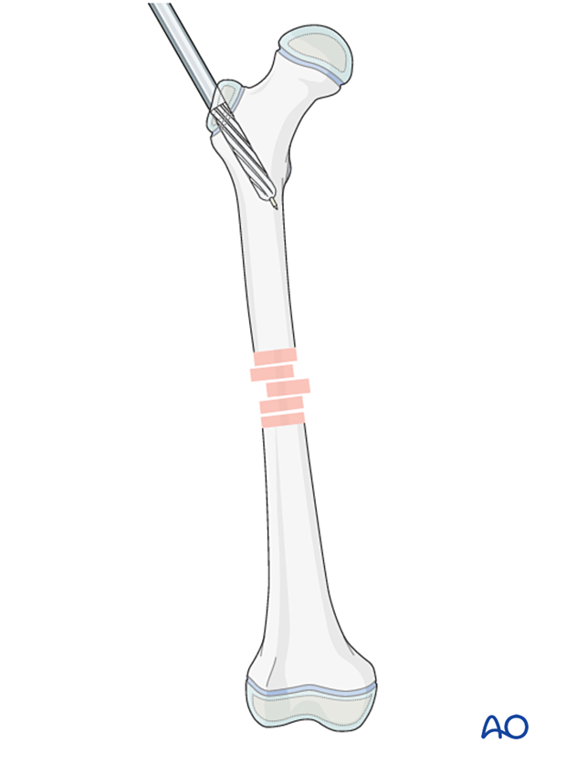
Overreaming of the proximal femur is a crucial step to facilitate insertion of the nail.
Open the femur with the opening reamer through the drill sleeve, which will provide a stop to the drill.
Ream the proximal 75 mm of the proximal femur up to 13 mm to allow the contoured nail to be inserted.
Remove the guide pin and insert an olive-tipped reaming wire to the level of the fracture zone.
5. Reduction
Reduce the fracture in a closed fashion with manipulation, traction, and direct pressure applied with a mallet or similar instrument.
Successful reduction permits passing of the olive-tipped reaming wire.
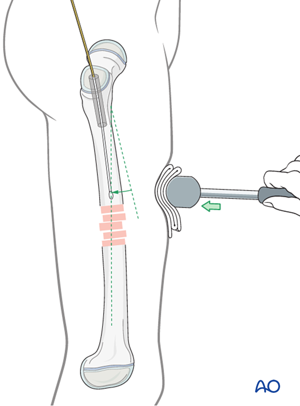
If this is unsuccessful use a bone hook or Schanz screw through a small incision.
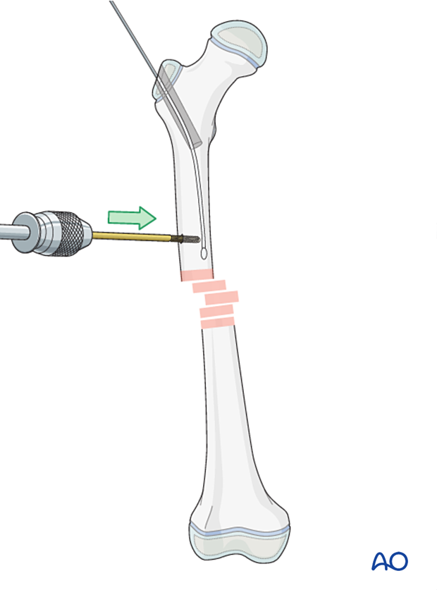
Open reduction (through a limited lateral approach) may be necessary if closed reduction cannot be achieved.

6. Opening and reaming the medullary canal
Advance the reaming wire across the fracture zone as far as the distal metaphysis, with the tip proximal to the growth plate.
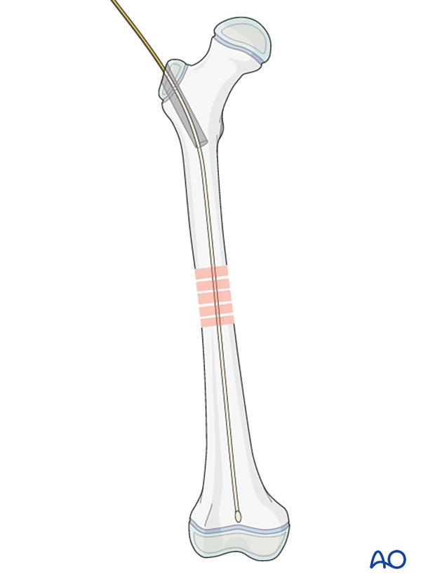
Confirm the central position of the reaming wire on both AP and lateral views.

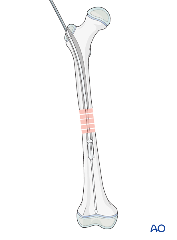
Ream the medullary canal 1–2 mm wider than the selected nail diameter to within 1 cm of the distal physis.
The guide wire is removed, immediately before insertion of the nail.
7. Nail insertion
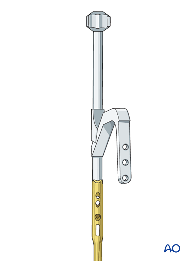
Assembling nail and insertion handle
Mount the insertion handle onto the nail.
Take care that the nail is of correct length, diameter and side. (Right and left sided nails are distinct due to the nail geometry.)
Nail insertion
Start inserting the nail manually with light taps, with the handle in an anterior position.
The handle will rotate into a more lateral position as the nail is advanced into the shaft due to the inner curve of the femoral canal.
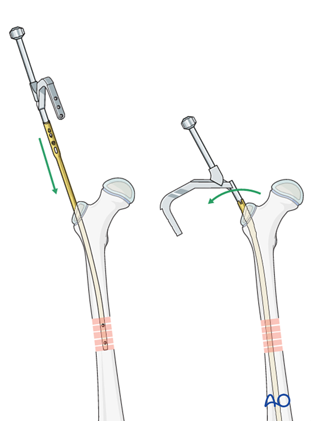
Confirm correct reduction under image intensification.
The nail should stop before the distal growth plate. Proximally the nail should be flush with the greater trochanter.
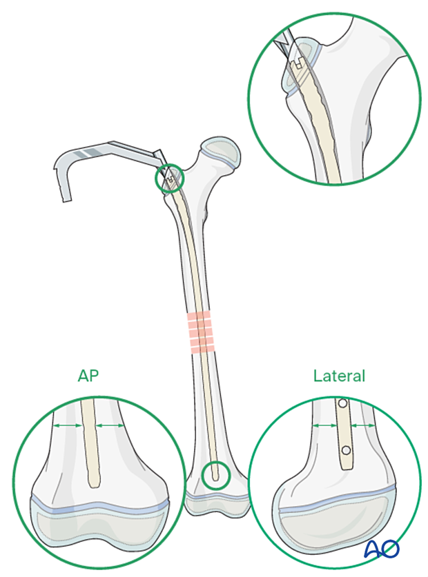
Proximal locking
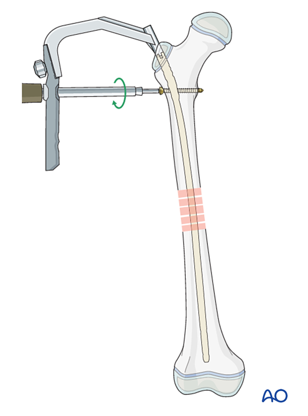
Insert the proximal locking screw first.
Usually the nail has several options for proximal locking screws. Here the insertion of a standard static locking screw is shown.
Assessment of rotational alignment
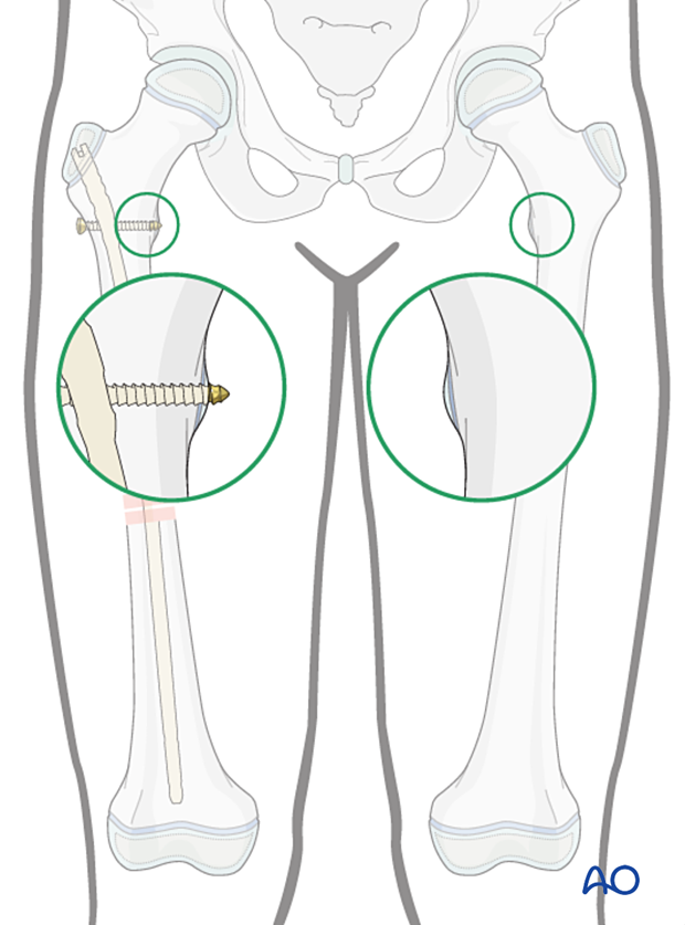
Before insertion of the distal locking screws assess rotational alignment by clinical examination.
It is difficult to assess rotation with a plain x-ray and whilst anatomical reduction of the fracture is a reasonable indicator, it should not be used as a surrogate for careful clinical evaluation.
For more detail see the additional material on assessment of rotation.
In this example, the knee is placed in the true AP position and the appearance of the lesser trochanter is compared with the uninjured limb.
Correction of length
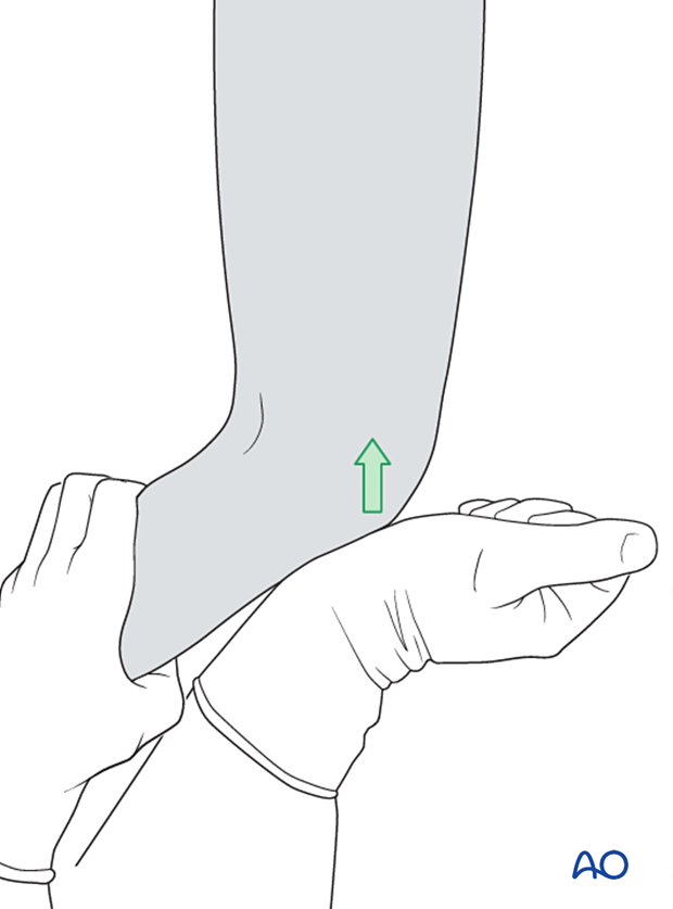
Prior to insertion of distal locking screws ensure the femoral length is correct. If the fracture is distracted, this is corrected by removing traction and impacting the fracture.
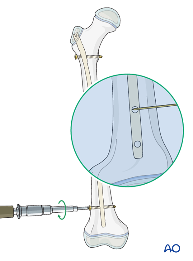
Distal locking
Insert distal locking screws using a free-hand technique:
- Align the nail to the image intensifier so that the screw hole forms a perfect circle.
- Make a stab incision over the screw hole.
- Exactly superimpose the point of the drill to the center of the locking screw hole.
- Pass the drill through the near cortex, and through the screw hole before engaging the opposite cortex.
- Uncouple the drill sleeve and check position with an image intensifier.
- Complete drilling the far cortex.
- Insert a bicortical screw.
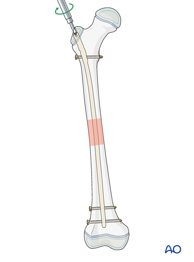
End caps
Insert an end cap to facilitate access for later removal.
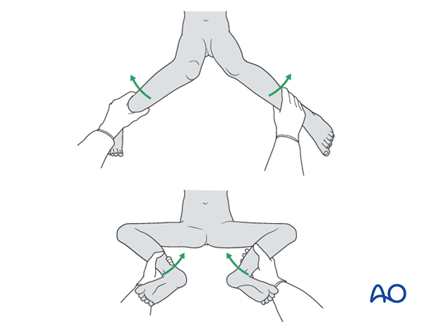
8. Final assessment
Check the range of internal and external rotation of the leg and compare with the contralateral limb.
Obtain final AP and lateral fluoroscopic views.
9. Aftercare
Immediate postoperative care
The patient should get out of bed and begin ambulation with crutches on the first postoperative day.
In most cases full weight bearing is permitted. With unstable fractures the patient may begin with partial weight bearing.

Analgesia
Routine pain medication is prescribed for 3–5 days postoperatively.
Neurovascular examination
The patient should be examined frequently, to exclude distal neurovascular compromise.
Compartment syndrome, although rare, should be considered in the presence of severe swelling, increasing pain, and changes to neurovascular signs.
Discharge care
Discharge from hospital follows local practice and is usually possible after 1–3 days.
Mobilization
The patient should ambulate with crutches and begin knee range-of-motion exercises.
Follow-up
The patient is usually reviewed 2 weeks after surgery for clinical and radiographic assessment, and wound check.
Clinical assessment of leg length and alignment is recommended at one-year.
Clinical assessment of leg length uses a tape measure from the ASIS to the medial malleolus.
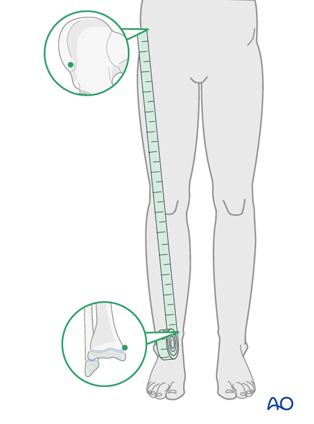
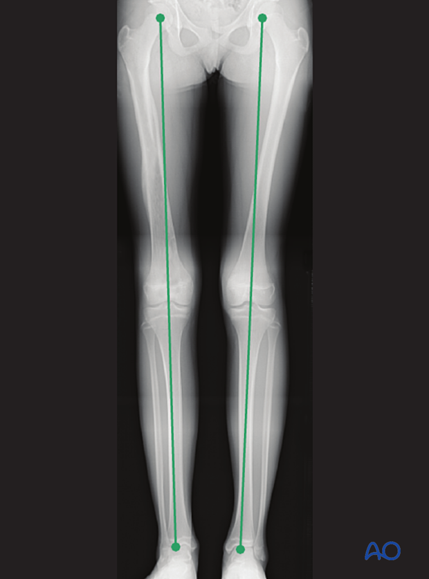
If there is any concern about leg length discrepancy or malalignment, long-leg x-rays are recommended.
Leg length is measured from the femoral head to the ankle joint.
Implant removal
If the patient develops symptoms related to the implant, it can be removed once the fracture is completely healed, usually 6–12 months following injury.


