ORIF - Lag screws with protection plate
1. Principles
Lag screw and protection plate
If nailing and MIPO are contraindicated, ORIF should be performed. If the fracture configuration does not allow axial compression, a lag screw should be used to achieve interfragmentary compression.
Depending on plate position and fracture configuration, the lag screw will be introduced either through a plate hole or outside the plate. If possible, insert the lag screw outside the planned plate. If not, the lag screw is introduced through one of the plate holes after application of the plate with one screw in each main fragment.
The remaining shearing and rotational forces have to be eliminated by a so called protection plate.
Introduction of a lag screw
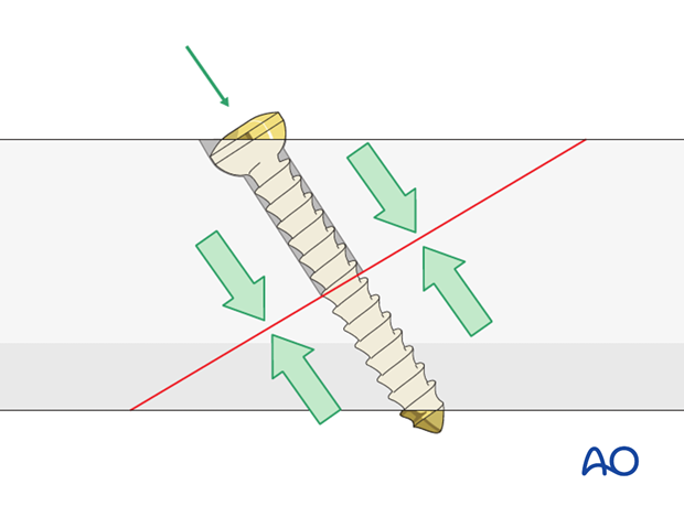
Introduce the lag screw as perpendicularly as possible to the fracture plane. The lag screw should be placed without soft tissue stripping and should not interfere with tibialis anterior tendon.
If it is an anterior-to-posterior screw it should be sufficiently countersunk so that the screw head is not prominent. A second reason for countersinking is to improve the congruency between the screw head and the surrounding bone in order to divide the pressure.
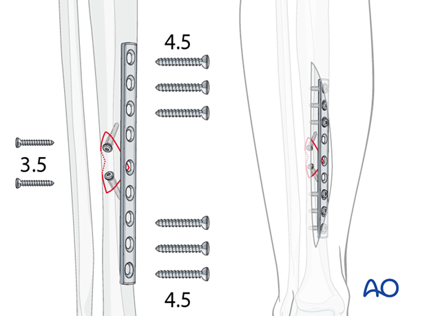
Options for small wedge fragments
Use of 3.5 mm screws
With small wedges, 4.5 mm screws may be too large. They can be replaced with two 3.5 mm lag screws. Given the typical size and load for the tibia, a 4.5 mm narrow DCP used as a protection plate.
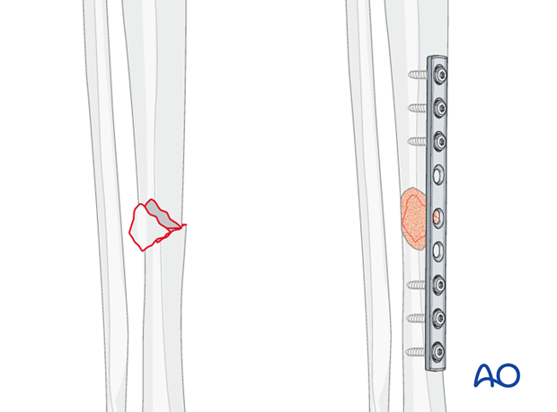
Use of bone graft
Often, in small wedge fragments, the periosteum has been completely stripped from the wedge fragment. In these cases, adding a small amount of bone graft (e.g. from proximal tibial metaphysis) over the wedge may promote healing.
2. Patient preparation and approaches
Patient preparation
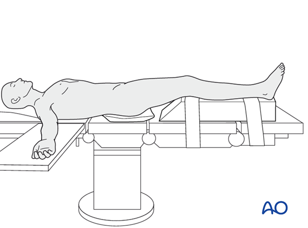
This procedure is normally performed with the patient in a supine position.
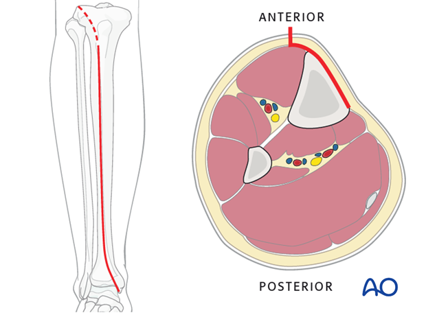
Anteromedial approach
The anteromedial approach is used most commonly for fractures of the distal third tibial shaft. However, it can be used to expose the entire anteromedial surface.
It is also useful for debridement and irrigation of open fractures when an incision on the injured subcutaneous surface is to be avoided.
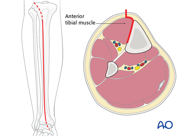
Anterolateral approach
The anterolateral approach is used uncommonly, but may be necessary when the medial soft tissues are compromised.
3. Reduction
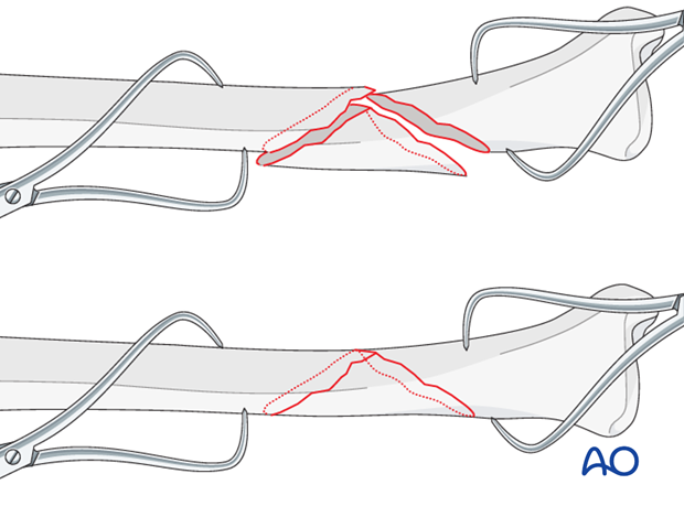
As the fracture is reduced with pointed reduction forceps it is also rotated into its anatomic position.
Pointed reduction forceps are best used in long oblique or spiral fractures where the reduction can be visualized over a longer way. In short oblique fractures where only part of the reduction is visible the axial alignment must be double-checked.
4. Lag screw insertion
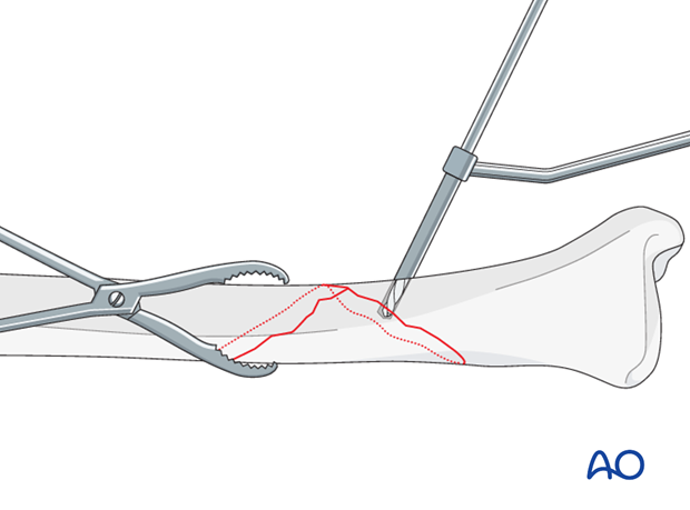
Gliding hole
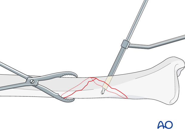
Use a 4.5 mm or 3.5 mm drill (according to chosen screw size) to create a gliding hole, located centrally across the fracture plane, away from the fracture line, and angled perpendicularly to the fracture plane at the chosen location.
Drill the near cortex only, using an appropriate drill sleeve.
Pilot hole for the thread
Insert an appropriately sized drill sleeve through the gliding hole to contact the far cortex.
Drill through the sleeve with the appropriate drill for the pilot hole, 3.2 mm for large fragment screws, 2.5 mm for small fragment screws.
Screw insertion
Measure the length of the screw and prepare the far cortex with the appropriate tap. Insert the chosen screw, tightening it carefully.
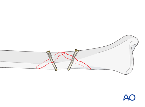
For longer spiral fractures, a second screw is inserted, using a similar technique. Both screws should be as perpendicularly to the fracture plane as possible at the site where they are inserted. Each hole should pass through the middle of the fracture spike, or of the fracture plane of the other fragment. If using two lag screws, extra attention should be payed to leave enough space for the protection plate.
5. Plate preparation
Determining length of plate (narrow 4.5 plate)
The plate length is determined by the fracture pattern and the fracture location. Choose a plate which is long enough to place 3 holes proximal and 3 holes distal of the fracture.
Pearl - Use of locking plates
If available, locking plates are used when shaft fractures extend towards the joint and leave the surgeon with a small distal fragment. By utilizing the angular stability capacity of the plate these small fragments can be held effectively.
Locking plates are especially useful in osteoporotic bone where the concept of low strain fixation and angular stability allows stable fixation in this poor quality bone.
Note
If a combination of a lag screw and locking head screws is planned, insert the lag screw first. Once a locking head screw has been inserted in one segment of a fracture, no further conventional screws should be added to this segment, as this will introduce unwanted forces.
Contouring the plate
Twisting the plate
The anteromedial surface of the tibial shaft twists internally approximately 20° as it approaches the medial malleolus.
The first step of plate contouring is to twist the plate so it matches the tibial surface upon which it will lie.
If the plate is bent before it is twisted, the process of twisting will alter the bend that has been created.

Matching the curvature
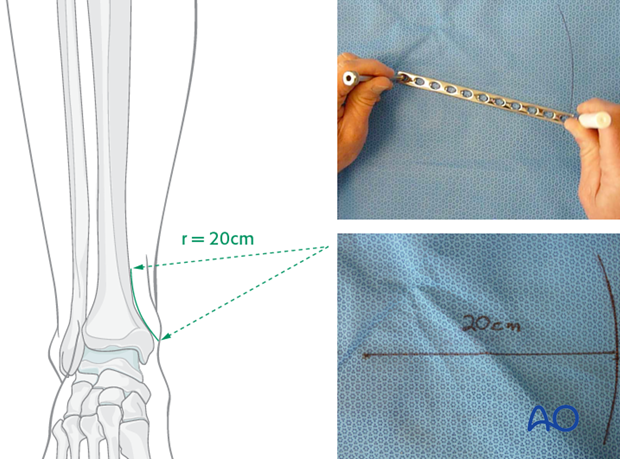
Depending upon the plate location, more or less bending of the plate will be required to match the contour of the intact (or reduced) bone. Much of the medial tibial shaft is quite straight, so that little bending is required. However, the distal medial surface has a significant concavity, with a typical radius of curvature of 20 cm as illustrated.
Such a 20 cm radius can be drawn on a sterile drape and used as a template for plates to be used in this location.
Bending the plate
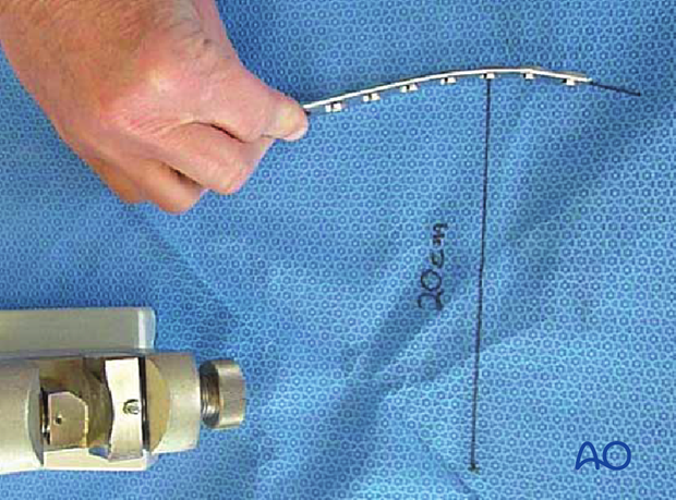
he plate can be bent with bending irons alone, but it is preferable to bend with a bending press, because the press gives more control.
In either case, the bending is done in small steps to produce a smooth contour. Contouring only takes place over the distal 10-12 cm of the plate. When finished, the plate should match the 20 cm radius of curvature.
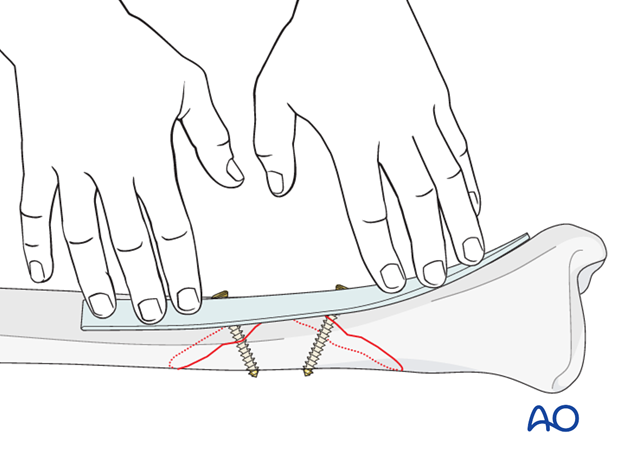
Alternative: with template
An aluminum template is adapted to the anatomically reduced fracture in the position where the plate is to be applied. The plate is then shaped to match the template.
6. Plate fixation
Application of the plate
No periosteal stripping should be done, either for plate fixation or screw placement, but there must be adequate soft tissue exposure sufficient to provide an area for the plate.
Rather than clamping the plate to the bone, it is often helpful to hold the plate to the bone with one well-placed screw in order to confirm that it is contoured correctly.
Be careful not to displace the fracture, as initial lag screws may lack strength. If possible, leave a reduction clamp across the fracture during plate application.
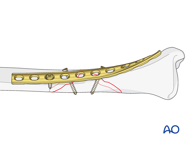
Insert remaining screws
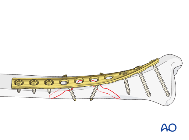
Then insert the rest of the screws, also in neutral positions using either the universal, or appropriate LC-DCP, guide.
Screws closest to the fracture site are placed first.
7. Aftercare of tibial shaft fractures
Weight bearing
If weight bearing without plaster is not advisable or possible, a walking cast is a better option than unprotected walking completely without weight bearing.
After intramedullary nailing, weight bearing is allowed in an earlier phase (immediately postoperatively) compared to plate fixation. After the latter, progressive weight-bearing is usually possible after 8-12 weeks.
If external fixation is considered as the definitive device, weight bearing starting at 10–15 kg should be encouraged early, as in plate fixation.
As soon as callus formation is visible and once there are no clinical signs of instability, the patient can start to bear full weight. After removal of the external fixator, it may be prudent to protect the leg temporarily in a splint or brace.
Follow-up
After suture removal 2 weeks after surgery, the patient should be seen every 4-6 weeks in follow-up with examination and x-rays until union is secure, and range of motion and strength have returned.
Inspection of external fixators every two weeks is optional.
Hardware removal
Interlocking screws are always removed.
As far as plates create stress raising, removal is advisable. The earliest time of implant removal being two years postoperatively.


