MIO - Compression plating
1. Principles
Indications
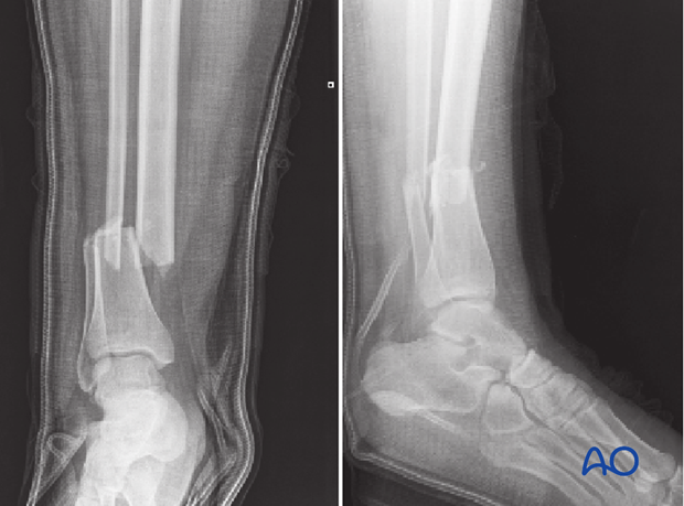
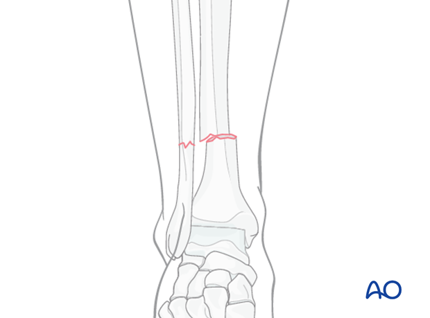
Compression plating can be used for any transverse, 2-part, tibial fracture.
It is especially good for treatment of diaphyseal fractures in children with open growth plates, where significant displacement is present and anatomical reduction is indicated.
MIO techniques are indicated for select transverse fractures where a closed reduction technique effectively restores an anatomical reduction.
Cautious use of MIO may permit compression plating in the case of compromised soft tissues, if they are sufficiently fit to withstand the procedure, and the size of the planned hardware. Submuscular plating may be safer than subcutaneous in these situations.
General considerations
Tibial shaft fractures near the knee or ankle may require plate fixation. MIO techniques are advantageous because they preserve fracture site biology. By limiting skin incisions and surgical dissection, using indirect reduction techniques and basic plating concepts, adequate fixation and alignment can be obtained with less additional injury. While multifragmentary fractures require a bridging technique, short oblique or transverse fracture patterns should be fixed with compression plating to achieve absolute stability and avoid the high-strain situation that occurs when a simple fracture is fixed without compression.
Preoperative planning
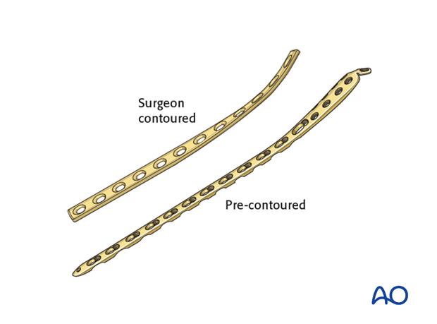
With MIO techniques, preoperative planning is of utmost importance and should include all steps of the procedure (including appropriate approaches, reduction techniques, instruments, and implants). Anatomically shaped plates are helpful but not necessary for this technique. Straight plates can be contoured to fit the bony surface.
Intraoperative imaging
With limited windows through the skin and no direct visualization of the fragments, image intensifiers are a key surgical tool for MIPO. The image intensifier field of view should be large enough to indicate axial alignment. Alternatively, full length standard x-rays may also be required. Always inspect the legs visually as an additional check for alignment errors.
The position of the C-arm is critical in order to achieve orthogonal views during surgery. This should be tested before surgery.
2. Patient preparation and approaches
Patient preparation
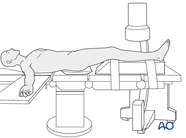
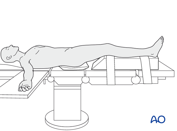
The patient is in a supine position on a radiolucent table or a standard operating table with a radiolucent extension. A pad is placed underneath the buttock to prevent external rotation.
A large foam bolster or cushion is placed under the affected leg to raise it above the opposite leg and facilitate lateral C-arm images.
Approaches
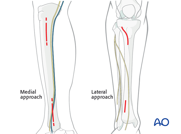
If the soft tissues allow, a medial approach is preferred because it is easier to pass the screws percutaneously with less soft-tissue interference.
The lateral approach should be chosen if the medial soft tissues are significantly injured.
3. Reduction
Reduction principle
The key to all fracture reduction is restoring axial length.
Ways of gaining length are:
- Manual traction
- Distractor/external fixator
- Use of reduction forceps
- Push-pull screws
- Articulated tension device (ATD).
Manual traction
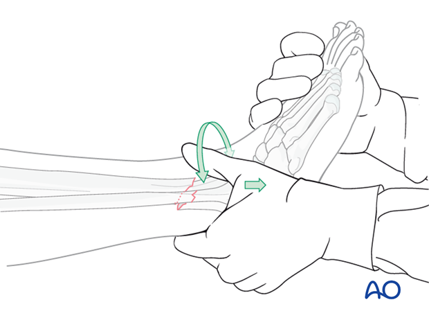
Apply longitudinal traction to the foot.
After correct length and axial alignment have been achieved, evaluate and correct the rotational deformity. One should determine the correct rotation from the uninjured extremity preoperatively.
Manual traction can be effective in fresh fractures; however it may be ineffective in fractures with soft-tissue contractures, significant shortening or early fracture healing.
Large distractor or external fixator
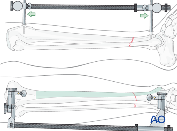
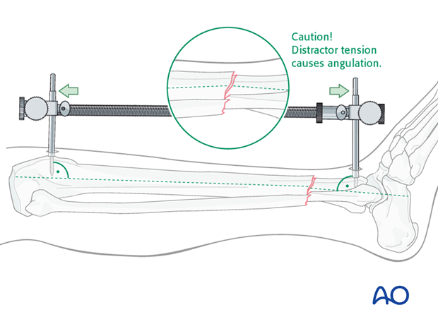
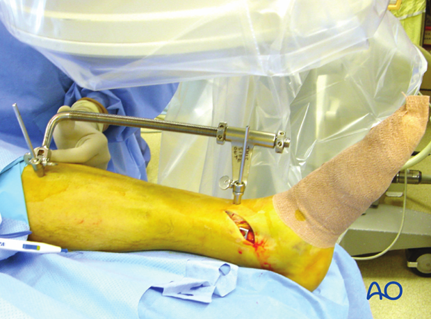
If manual traction is not successful, use a large distractor for closed reduction. Place a Schanz pin in both proximal and distal fragments. Distraction is applied across these pins by turning the nut on the threaded rod.
If the plate is to be placed medially, then the distractor should be placed anteriorly.
Note: The pins must be placed in the same anatomical plane, so that when the distractor is attached, rotational alignment of the tibia is correct. With the distractor in place, rotational alignment is hard to change.
Pitfall
With significant tension of the distractor, the fracture may angulate, with concavity on the side opposite to the distractor.
If the distractor is medial, it can produce valgus. If it is anterior, it can cause flexion (apex-anterior angulation) at the fracture, as shown here.
If the surgeon recognizes this problem, it can be corrected by adjusting the distractor pin clamps to favor the opposite deformity.
Solution
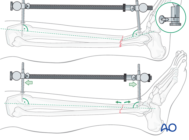
The distractor or external fixator pins can be adjusted to correct the angular deformity. When the distractor is lengthened, tension is asymetrically applied to the soft tissues, so that angulation is produced at the fracture. The side opposite the distractor becomes concave.
As shown here, the distractor pin-clamps have been angulated to produce apex-posterior angulation. As tension is applied, length is restored, and the apex-posterior deformity is corrected.
Pointed reduction forceps
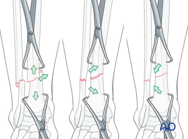
With transverse fractures, the forceps cannot be applied to compress the fracture surfaces. In this situation, percutaneous pointed reduction clamps, one in each bone segment, are helpful to adjust the fracture.
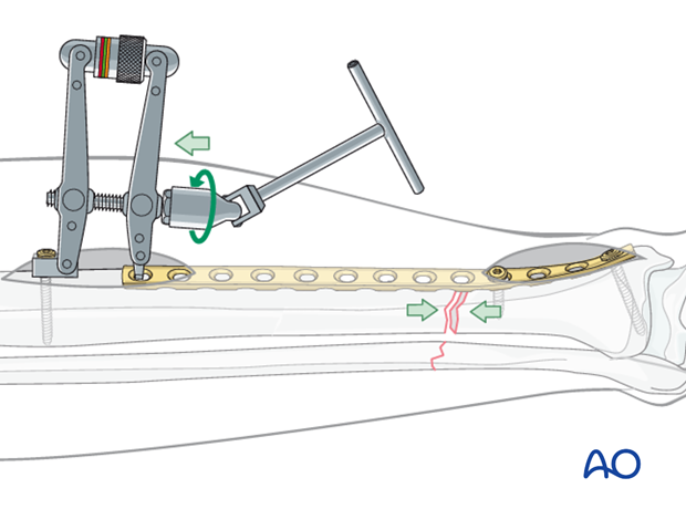
Alternative: Articulated tension device (ATD)
To use the ATD, in distraction mode, a precontoured plate is applied to one of the main fracture fragments. The distracting forces are then applied with the ATD against the opposite end of the plate.
Distraction aids precise fracture surface reduction.
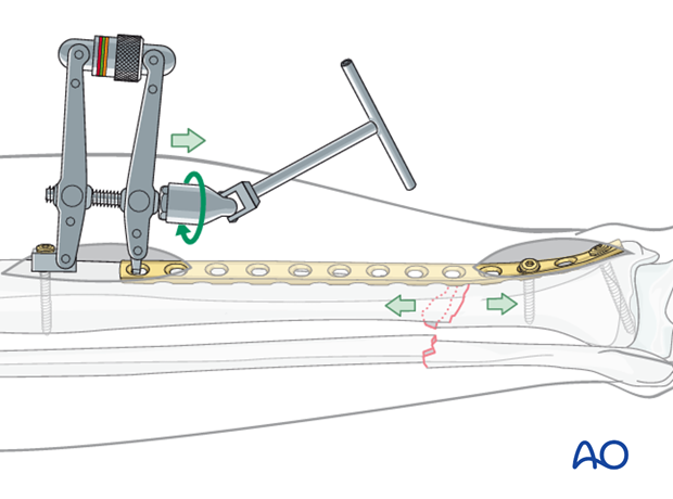
With the fracture satisfactorily reduced, the ATD is used in compression mode to load the fracture and achieve interfragmentary compression, and absolute stability.
Remember that the plate should be overcontoured slightly at the fracture site, so that compression occurs opposite as well as adjacent to the plate.
Alternative: Push-pull screw
A precontoured plate is applied to one of the main fragments. A bicortical screw is then placed near the free end of the plate and the bone spreader is used to apply distraction force between the screw and the plate.
Distraction aids precise fracture surface reduction.
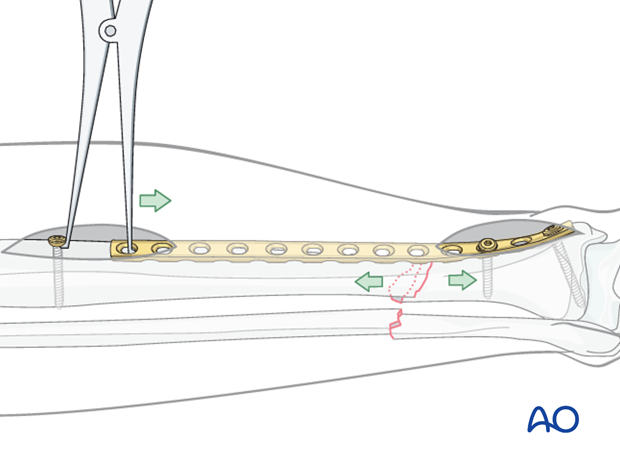
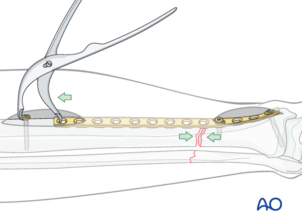
Fracture site compression can be applied using a Verbrugge clamp between the push-pull screw and the plate. Compression is applied once the fracture is satisfactorily reduced.
Remember that the plate should be overcontoured slightly at the fracture site, so that compression occurs opposite as well as adjacent to the plate.
Rotation
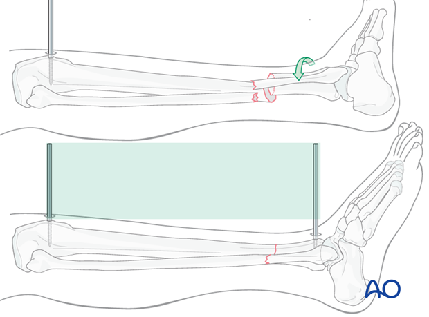
Rotational alignment must be considered during application of any of the previous reduction methods.
The distractor or simple external fixator are uniplanar devices. Rotation of the fracture fragments cannot be adjusted significantly once the pins have been placed and attached to the device.
Thus, the pins should be placed so that when they are in the same plane, the fracture is reduced.
Final reduction of the fracture
Final reduction of the fracture may be difficult with pointed reduction forceps due to the short obliquity or transverse nature of the fracture.
Once length has been restored, translation of the fragments can be corrected using either manual force, percutaneously placed Schanz screws, spike pusher or clamps. After translation has been corrected, the distraction force can be removed. In many cases the fracture will remain reduced due to the transverse orientation of the fracture line.
In some cases, overdistraction is required to correct the translational deformity.
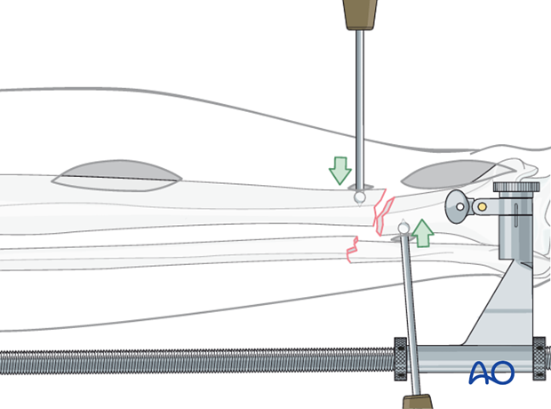
Plate
Reduction can also be achieved by reducing the fracture to the plate. With the plate positioned against one fracture fragment, the adjacent fracture fragment can be pulled to the plate with a well-placed cortical screw. In this way, translation of the fracture fragments is corrected.
The plate must be shaped anatomically to fit the bony surface for this technique to be effective.
The surgeon must also ensure that reduction is adequate in the opposite orthogonal plane (correct on lateral view, as well as the AP shown here).
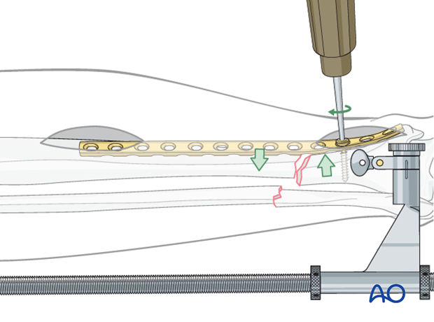
4. Plate selection and preparation
Choice of the plate
Plate length is based upon symmetry above and below the fracture zone. At least 3-4 screw holes on either side of the fracture are necessary.
Another guideline, when fracture location permits, is that the plate should be roughly three times the length of the fracture zone.
Generally, longer plates with less screws are most effective.
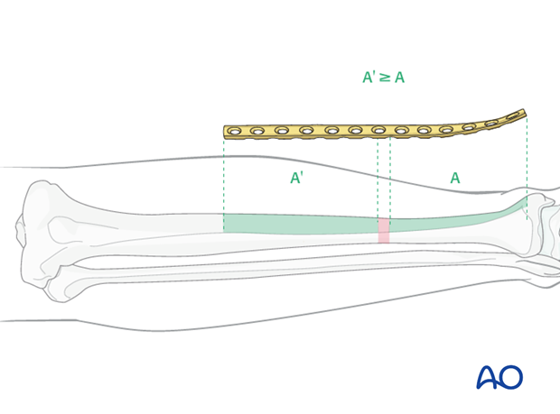
When the fracture zone is very distal or proximal, there may not be room enough for symmetric plate length in the segment nearest the articular surface. In this situation, a plate with multiple hole options in the metaphysis is chosen to improve fixation in the short periarticular segment.
A locking plate may be indicated if the bone quality is poor or when the fracture extends into softer metaphyseal bone.
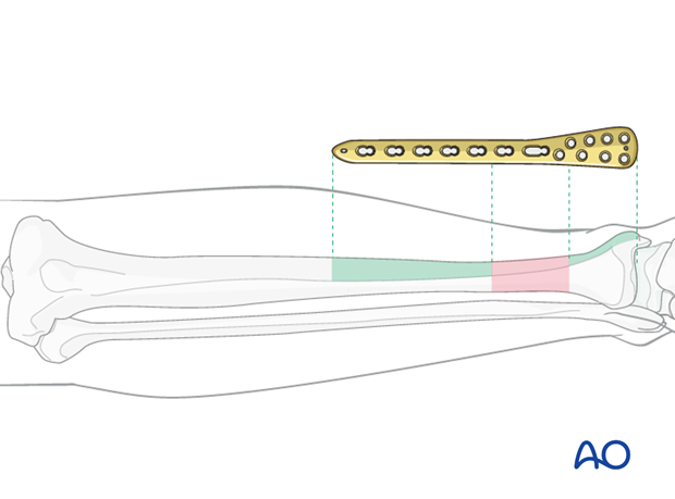
Traditionally a 4.5 mm plate has been advised for the tibial shaft. Its advantages include increased plate thickness and larger screw size for added strength. These plates are, however, more difficult to contour and may be too prominent.
A 3.5 mm plate offers improved contourability and multiple screw options in metaphyseal (end-segment) zones. However, they are less durable than the large fragment plates.
Another consideration is the choice between an anatomically precontoured plate or one which the surgeon contours. For plates which need to be contoured, the following steps have to be employed.

Twisting the plate
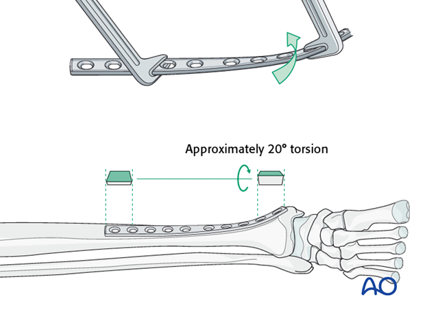
The anteromedial surface of the tibial shaft twists internally approximately 20° as it approaches the medial malleolus.
The first step of plate contouring is to twist the plate so it matches the tibial surface upon which it will lie.
If the plate is bent before it is twisted, the process of twisting will alter the bend that has been created.
Matching the curvature
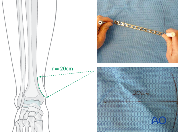
Depending upon the plate location, more or less bending of the plate will be required to match the contour of the intact (or reduced) bone. Much of the medial tibial shaft is quite straight, so that little bending is required. However, the distal medial surface has a significant concavity, with a typical radius of curvature of 20 cm as illustrated.
Such a 20 cm radius can be drawn on a sterile drape and used as a template for plates to be used in this location.
Bending the plate
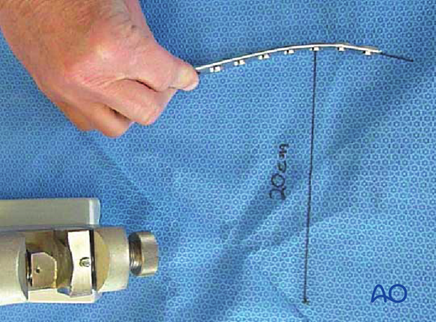
The plate can be bent with bending irons alone, but it is preferable to bend with a bending press, because the press gives more control.
In either case, the bending is done in small steps to produce a smooth contour. Contouring only takes place over the distal 10-12 cm of the plate. When finished, the plate should match the 20 cm radius of curvature.
5. Plate application
Plate insertion
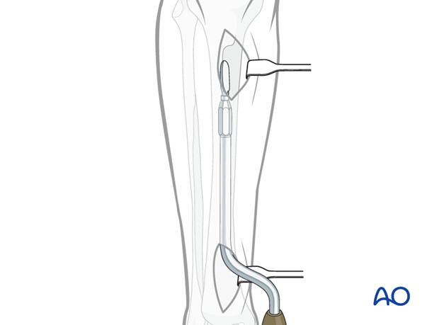
An incision is made over the distal tibia and the plate is slid under the subcutaneous tissues.
If a locking plate or an anatomically contoured plate is used, the specifically designed end of the plate will facilitate this passage. With a conventional LCDC plate, it may be necessary to use a periosteal elevator to create a subcutaneous tunnel.
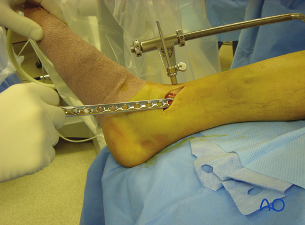
If available, the subcutaneous tunneling device could be used.
Position of the plate is adjusted on both the AP and lateral views. At this point, the plate can be provisionally held with K-wires.
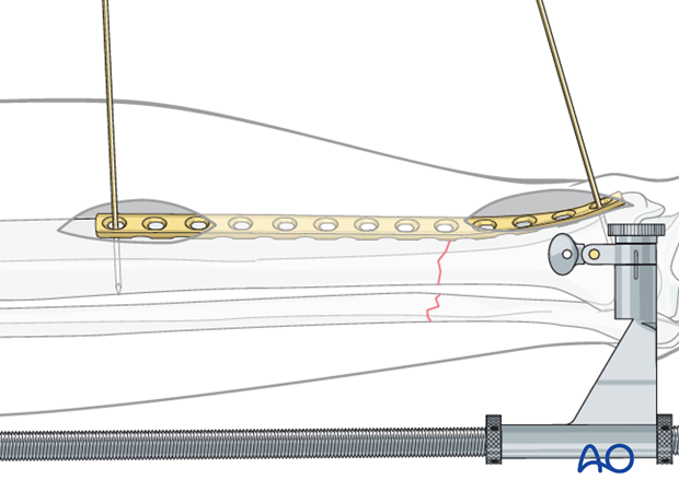
Initial screw placement
Through an image-directed stab wound, place the first screw according to antiglide principles (closing any gap between bone and plate to resist axial displacement) to improve axial alignment.
Reduction will only result if correct length has been achieved first.

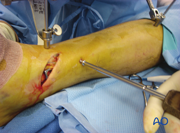
The initial screw must engage both cortices for secure purchase before it is tightened to reduce the fracture. This screw may then be too long. It can be exchanged later, after additional screws are placed.
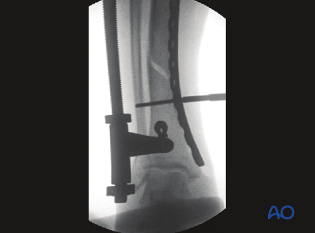
Compression screw
Fracture compression is applied after reduction. This may be done with the articulated tension device or a push-pull screw and Verbrugge clamp.
Additional compression can be applied to a well-reduced fracture using a screw in the opposite main bone fragment. This is placed eccentrically in a self-compressing (DC) plate hole with an appropriate guide.
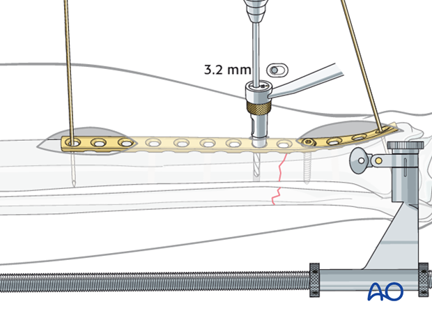
Pearl: Percutaneous screw insertion
Screws can be inserted into both ends of the plate through the small incisions made to insert the plate. The position of the screw holes in the central portion of the plate can be located by placing a plate of similar length on the skin over the inserted plate. The position of the screw holes can then be marked on the skin.
Special drill sleeves are available for safe percutaneous insertion of screws into conventional plates.
Alternatively, lateral fluoroscopic imaging can assist the surgeon with plate hole location.
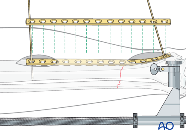
Insertion of remaining screws
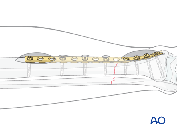
Place the remaining screws at appropriate intervals. Remember that fixation is better with longer plates, and that in the diaphyseal segment fewer screws are required.
Exchange long screws for those of the proper length.
6. Aftercare of tibial shaft fractures
Weight bearing
If weight bearing without plaster is not advisable or possible, a walking cast is a better option than unprotected walking completely without weight bearing.
After intramedullary nailing, weight bearing is allowed in an earlier phase (immediately postoperatively) compared to plate fixation. After the latter, progressive weight-bearing is usually possible after 8-12 weeks.
If external fixation is considered as the definitive device, weight bearing starting at 10–15 kg should be encouraged early, as in plate fixation.
As soon as callus formation is visible and once there are no clinical signs of instability, the patient can start to bear full weight. After removal of the external fixator, it may be prudent to protect the leg temporarily in a splint or brace.
Follow-up
After suture removal 2 weeks after surgery, the patient should be seen every 4-6 weeks in follow-up with examination and x-rays until union is secure, and range of motion and strength have returned.
Inspection of external fixators every two weeks is optional.
Hardware removal
Interlocking screws are always removed.
As far as plates create stress raising, removal is advisable. The earliest time of implant removal being two years postoperatively.


