Infrapatellar intramedullary nailing
1. Principles
Intramedullary fixation is suitable for the majority of diaphyseal and metadiaphyseal tibial fractures. With newer nail designs and attention to technique, nailing can be extended to both proximal and distal extraarticular fractures.
One approach for this procedure is infrapatellar. The advantage of this approach is that it does not violate the knee joint. This technique is ideal for diaphyseal fractures.
If the medullary canal is deformed (eg, prior fracture, developmental abnormality, or preexisting hardware) nailing may not be possible or may be more difficult.
If severe bacterial contamination or infection are present, nailing may spread infection through the medullary canal and should be avoided. External fixator pins are a common source of contamination. If such pins appear to be infected or have been present for more than 2–3 weeks, preliminary pin removal, debridement, and antibiotics may be advisable before nailing.
Intramedullary nailing in polytraumatized patients, particularly those with pulmonary injuries, may cause respiratory distress.
Available tibial nails
Currently available tibial nails have locking screw holes close to both ends, in multiple orientations, for better fixation of proximal and distal fractures. Some nails even offer fixed angle locking screws. The nails may be either solid or cannulated (hollow). Use of solid nails may result in reduced incidence of infection because they have no internal dead space.
The surgeon should be familiar with the nails available to them, particularly the available sizes. Instrumentation and details of technique vary among nail systems. This should be considered in preoperative planning and surgery.

2. Reaming
Reamed nailing
The diameter of the tibial medullary canal varies between 13 mm and 8 mm or less. Reamers can be used to enlarge the medullary canal for larger diameter nails. Such nails permit larger diameter locking screws. The strength and durability of screws and nails increases with their diameter. The medullary canal should be reamed so that it is slightly larger than the intended nail diameter (usually about 1.5 mm more), to ease nail insertion. The image illustrates a non-reamed nail on the left, and a reamed nail on the right. Stability is increased with the reamed technique, because the nail fits snugly in a longer portion of the tibial shaft.
Reaming is currently favored for most tibial nailing, but this should be done carefully when the isthmus of the tibial canal is narrow.

Reaming damages the medullary blood supply and causes temporary thermal necrosis of the diaphyseal bone. Theoretically, this increases the risk of infection, which may be relevant for open fractures. Clinical studies have not demonstrated this.
The surgeon should consider if the benefits of reaming are worth the associated risks, particularly in severe open fractures.
The individual patient’s medullary canal size, as well as probable mechanical stresses, must be included in this consideration.
Studies have shown increased union of tibial shaft fractures using reamed compared to unreamed intramedullary nails.

Reamers
These may be either cannulated and motor driven, or solid hand reamers.
Reamers should be sharp so they cut the bone with little friction and should have deep flutes and a small diameter shaft. The goal is to minimize pressure in the canal ahead of the reamer and to avoid friction and resulting overheating of bone and surrounding soft tissues (with resulting full-thickness necrosis of both).
If the reamer is not cutting bone easily, remove it, clear bone clogging the flutes, and resume reaming slowly and cautiously.
The first reamer of a series should be shaped so that its tip cuts into the bone. Subsequent reamers need only cut against the sides of the medullary canal.
The illustration shows a solid hand reamer (left) and a motor-driven reamer (right).

Teaching video: reamed nailing technique
AO teaching video: Tibia Fractures - Intramedullary Nailing with the Expert Tibial Nail (with reaming)
Non-reamed nailing
Non-reamed nailing was initially developed to theoretically reduce the risks of infection and pulmonary dysfunction from embolized medullary debris. These benefits have not been shown to be clinically significant. Since smaller diameter, “non-reamed” nails are mechanically weaker, particularly with regard to smaller locking screws, their reoperation rate is higher.
Such nails may be used for smaller diameter medullary canals, or selected indications, (eg, increased risk of infection) according to the surgeon’s preference. These nails are also ideally suited for use in healthcare settings where resources are limited, ie, lack of a fluoroscopy unit.
Teaching video: non-reamed nailing technique
AO teaching video: Tibia Fractures - Intramedullary Nailing with the Expert Tibial Nail (without reaming)
3. Locking screws
Modern IM nails permit placement of locking screws through bone and nail, to improve fixation both proximally and distally. Locked nails permit stable fixation which controls length, rotation, and alignment. Some nails offer fixed angle locking of screws proximally and distally.
When locking nails were first introduced, their potential for impairing healing was recognized. Delayed removal of locking screws (known as “dynamization”) was often advised if the fracture was healing slowly. Length-stable locking is often called “static” locking.
Some locking screw holes are designed with an oval shape so that a screw at one end of the oval will allow some longitudinal motion but still control rotation as well as limit shortening to the length of the oval. These have been called “dynamic locking” screw holes (see illustrations).
To ensure adequate fixation of acute tibial fractures, use of locking screws both proximally and distally is advisable. Dynamic (oval) rather than static (round) holes may be used when the fracture pattern is length-stable.
More information on the use of locking screws is provided in the Intramedullary nailing basic technique.

4. Patient preparation and surgical approach
Many nailing systems now come with instrumentation sets that allow differing patient positioning and surgical approaches which can aid with fracture reduction and surgical fixation. Please check the instrumentation sets available in your institution.
Patient preparation
This procedure is normally performed with the patient in a supine position for nailing with the knee flexed to allow access to the proximal tibia anterior and inferior to the patella (infrapatellar).
More information about patient positioning can be found here:

Approach
For this procedure an intramedullary nailing approach is used using infrapatellar instrumentation.
More information about this approach can be found here: Infrapatellar approach for intramedullary nailing of the tibial shaft

5. Reduction and preliminary fixation
Preliminary remark
Reduction is an essential part of intramedullary nailing. The fracture must be reduced to allow guide-wire placement, during reaming, and during nail insertion. It is important to restore length, angulation, and rotation. Even after guide-wire insertion, further correction of alignment may be needed to avoid deformity. This should be done before reaming and nail insertion.
Reduction is usually more challenging with proximal and distal fractures as well as with delayed treatment. Sometimes only mild traction and rotational adjustment are required. Percutaneous reduction aids (pointed reduction forceps, Schanz screws or ball-spike pusher) may allow reduction without opening the fracture. With other fractures, open reduction may be necessary.
The surgeon usually begins with less invasive reduction techniques, and, if they do not succeed, progresses to techniques which require more fracture exposure.
Different reduction techniques are illustrated below.
Manual traction
Depending on the patient’s positioning and the type of OR table, one or two people may be required to perform manual traction.
The illustration shows a padded triangular radiolucent supporting frame, placed proximal to the popliteal fossa. It provides countertraction when the fracture is lengthened with distal traction.
For patients positioned on a radiolucent table without knee support, one person holds the leg proximally and the other pulls the leg distally.
During traction, the reduction is controlled by palpating the anteromedial surface and crest of the tibia.

Using a distractor
If used, a large distractor is usually placed in the coronal plane. It lies posterior to the tibia, either laterally or medially. Placement should not obstruct the insertion of locking screws or intraoperative fluoroscopy.
The proximal Schanz screw must be proximal and sufficiently posterior to avoid blocking the nail. Place it parallel to the tibial plateau to aid proximal fracture alignment. The distractor’s distal pin should be outside the intended nail location, posteriorly in the distal tibia, or in the talus.
An external fixator may be used instead of a distractor.

Joysticks
To aid reduction, a “joystick” (in this case a Schanz screw on a T-handled chuck) can be placed percutaneously into either or both main tibial fragments. The Schanz screw should have unicortical purchase so that it does not block the guide wire, reamer, or nail.

Percutaneous reduction forceps
Oblique or spiral fractures can often be reduced with pointed reduction forceps applied percutaneously.

Open reduction
In the event of delayed treatment, or if a bone fragment is incarcerated in the canal, open reduction is performed.
In open reduction, careful preservation of the periosteum, and peripheral soft-tissue attachments is recommended. A mini-open technique should be considered if appropriate.
Locate the fracture by palpation or with fluoroscopy. Make a small longitudinal incision over the fracture. Avoid making an incision of the anteromedial surface of the tibia as wound healing can be impaired. Extend the incision sufficiently for access. Free up one side of the fracture at a time, with minimal dissection.

Oblique fractures
If the fracture is oblique, a bone clamp, placed percutaneously, with its tips perpendicular to the fracture plane, can be used to compress the fracture surfaces. Together with some traction, this helps restore length as well as fracture apposition.

Transverse fractures
If the fracture is transverse, it may be reduced with manipulation using clamps on the bone ends. This may require excessive exposure. Percutaneous Schanz screws, or percutaneously applied pointed reduction forceps, as illustrated, are less invasive.
The technique with clamps is as follows:
- Free up the ends of both fracture fragments.
- Align the crest of both fragments. This will ensure proper rotation.
- Flex the fracture to 45 degrees, or enough to place one fragment onto the other.
- Approximate the cortical edges, and gradually straighten the fracture, which compresses the fracture site.
- Recheck alignment.

Alternatively, a Hohmann retractor can be used for reduction by placing it between the fracture fragments and prying them apart. It is important to hold this position for at least 30 seconds in order to allow the viscoelastic tissues to stretch gradually.
It is very important to maintain the reduction while the nail is inserted. This often requires an assistant, or temporary use of distractor, external fixator, or plate with unicortical screws.

Plate as reduction aid
It may be difficult to achieve and maintain reduction in proximal tibia fractures.
As illustrated, a small plate with unicortical screws can be used, both as a reduction aid and to hold the reduction during nail insertion.
This is an open technique, but little soft-tissue dissection is required. The plate can be left in place after the nail is inserted.
It is important to plan appropriate screw trajectory to avoid interference with the nail insertion.

Fixing a straight plate into the distal tibial fragment pushes the proximal fragment into alignment, thus correcting the gap and apex-anterior angulation. Adding a proximal screw increases stability, helping to avoid redisplacement during nail insertion.

Reduction difficulties
Delayed reductionIf nailing is delayed, a temporary external fixator can maintain distraction, thus aiding reduction. If the fracture consolidates with shortening, closed reduction will be difficult to achieve, particularly after 10–15 days. If an initial attempt at closed reduction is unsuccessful, open the fracture and release enough peripheral callus to allow reduction.

6. Creation of the nail entry site
Approach
For details about determination of the entry point and incising the skin, please refer to the Infrapatellar approach for intramedullary nailing of the tibial shaft. Remember that a properly placed entry site is essential for successful intramedullary nailing.
Obtaining appropriate fluoroscopic views of the proximal tibia
It is imperative to obtain appropriate AP and lateral views of the proximal tibia to ensure that the proper entry site for the tibial nail is obtained. A proper AP view has the lateral border of the tibial plateau bisect the fibular head. A proper lateral view has the femoral condyles superimposed on each other. The entry point for a tibial nail on the lateral view should be at the anterior edge of the joint line and on the medial aspect of the lateral tibial spine on the AP view.

Tools for opening the bone
Using fluoroscopy, with the appropriate AP and lateral views, a preliminary guide wire helps locate the proper entry site. Various cannulated instruments can be inserted over such a pin. Alternatively, a solid awl can be used for the same purpose. Make sure that the location is correct before the full opening is created.

Insertion of the guide wire
Insert the guide wire parallel but posterior to the tibial crest, and thus in the center of the medullary canal.
Press the guide wire into the bone so the tip does not slip. While entering the bone, correct the guide wire alignment by pushing the proximal end of the wire posteriorly. This brings the wire almost in line with the axis of the tibia, as illustrated.

The illustration shows proper guide wire placement in the frontal plane. It is essential that the surgeon takes frequent AP and lateral fluoroscopic views while the guide wire is inserted to ensure that the proper trajectory of the guide wire is obtained.

If the procedure is done without fluoroscopy, landmarks as described must be used with care to place the entry site in line with the medullary canal.

Opening the cortex and proximal tibia
The illustration shows entry creation with a cannulated drill or entry reamer inserted over the previously placed guide wire. A protective sleeve minimizes soft-tissue injury.

Alternative: cannulated cutting tool
Alternatively, one can use a cannulated cutting tool over the previously placed guide wire to open the entry site, as illustrated.

Alternative: curved solid awl
In addition to cannulated cutting tools, or drills, the cortex can be opened with a solid awl.
The important principle is that the entry site must be placed so that the nail enters the tibia freely.

7. Guide wire insertion
Ball-tipped guide wire
Once the proximal tibia has been prepared with the entry reamer, the initial guide wire is removed, and a ball-tipped guide wire is carefully tapped down the medullary canal to the distal metaphysis. This requires fracture reduction. If reduction is difficult or the fracture is comminuted, special efforts may be required.

Bending the guide wire
Slightly bending the guide wire 10–15 mm above its tip is helpful for the following reasons:
- Passing through the fracture site into the distal fragment is easier, since rotation of the guide wire redirects its tip
- It facilitates the proper position of the tip in the distal metaphysis
Do not bend the guide wire excessively or the reamer and/or nail will become incarcerated in the guide wire.
Fluoroscopic control
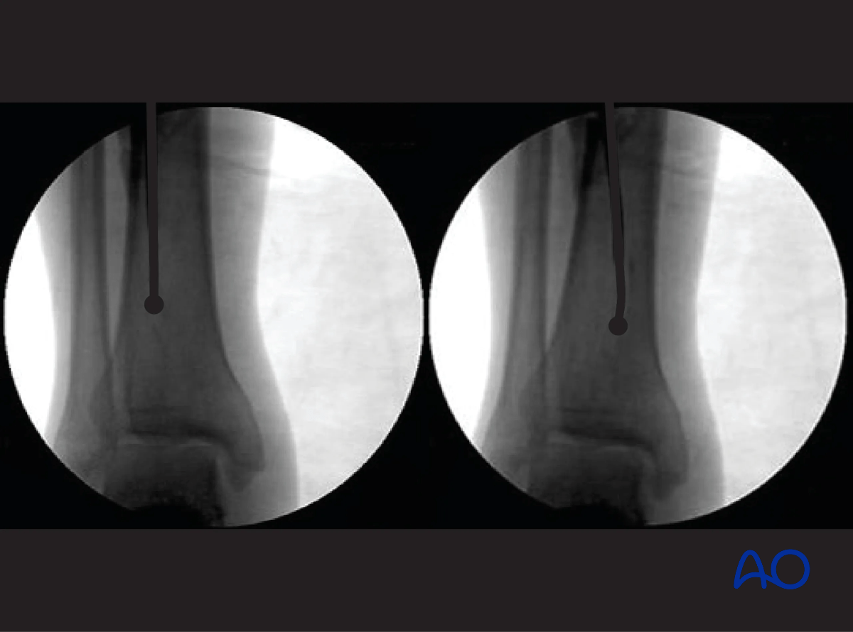
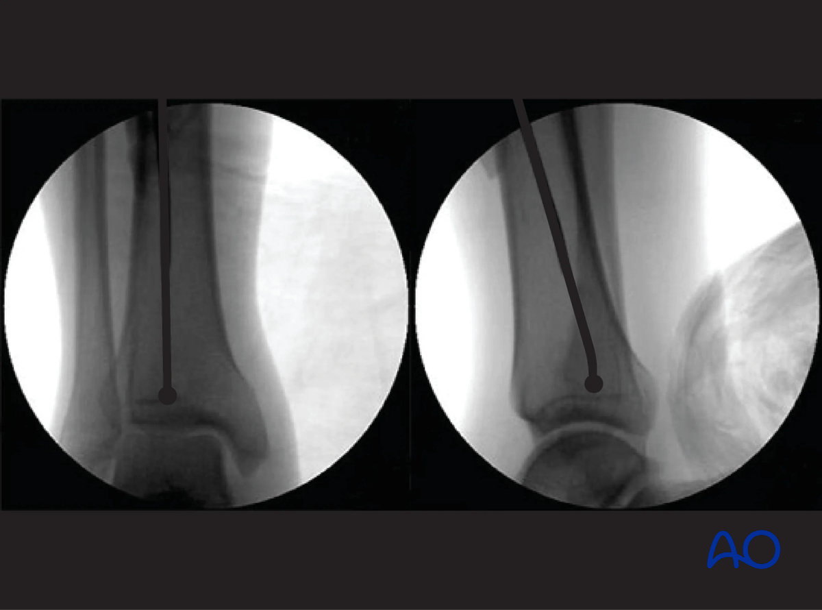
Use fluoroscopy to check that the guide wire is positioned above the center of the ankle joint.
Ensure a proper AP and lateral image of the ankle is taken. The end of the ball-tip guide wire should be seated at or just above the level of the epiphyseal scar. This is especially the case for more distal fractures of the tibia.
8. Determination of nail length
Preoperative planning is essential. In multifragmentary fractures, or in open fractures with bone loss, the uninjured leg can be used as a guide during preoperative planning to help select an appropriate nail. In bilateral fractures, the less comminuted side should be used to determine the length and diameter of the nail.
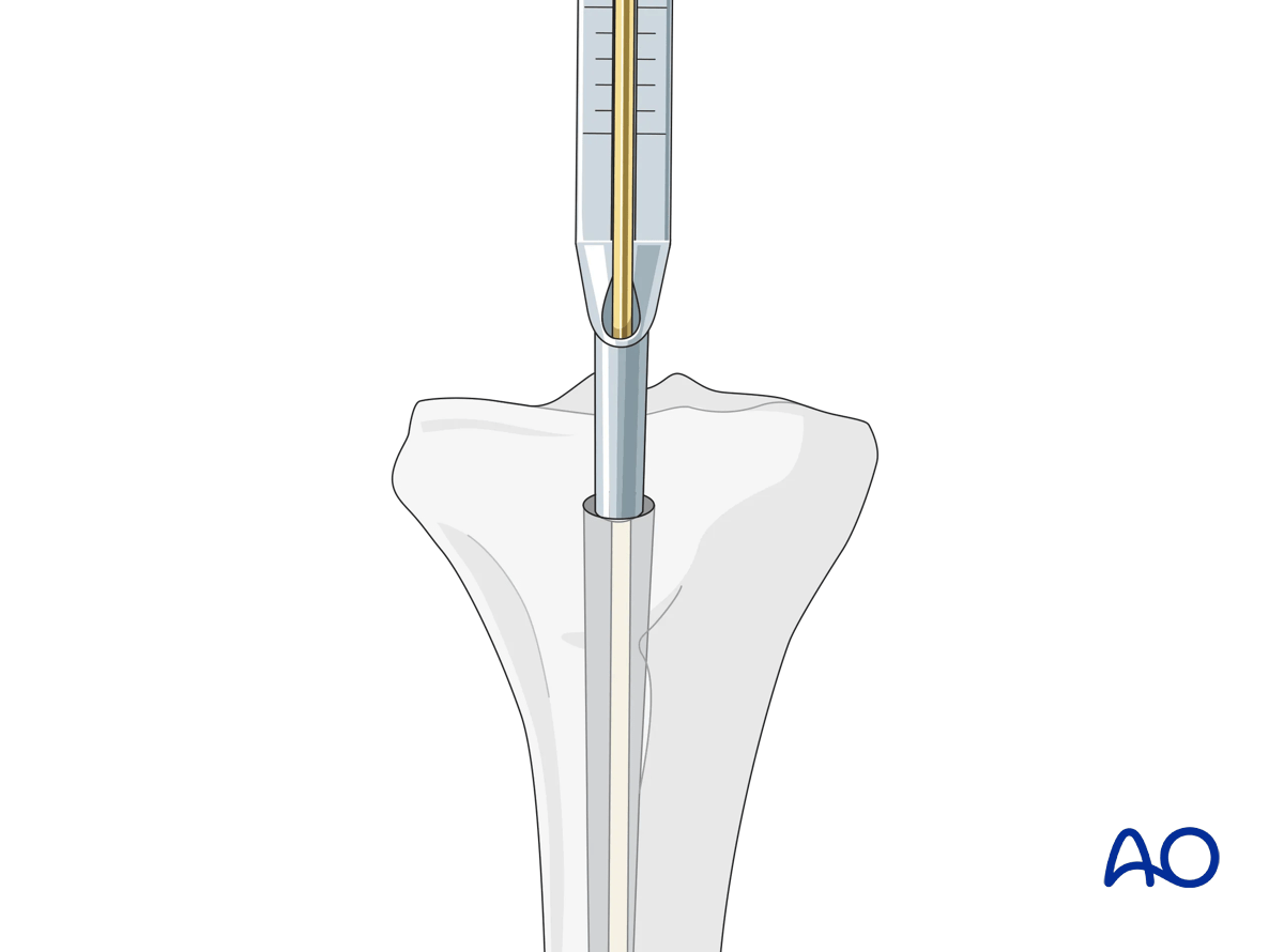
Determination of length using a depth gauge
All intramedullary nailing sets come with a depth gauge that is slid over the guide wire to determine the length of the nail to be inserted. Fluoroscopy is used to ensure correct position of the guide wire before length measurement is made.
Other options include using a radiographic ruler or measuring off a second guide wire of equal length.
9. Reaming and determination of nail diameter
Reaming
Insert the cannulated, flexible-shaft reamer over the ball-tipped guide wire. If inflated, it is recommended to deflate the tourniquet (to enhance blood flow to the tibia and decrease the risk of thermal necrosis).
Begin with an end-cutting reamer and proceed sequentially to larger reamer diameters, usually in increments of 0.5 mm. Protect the soft tissues at the entry site during this process with a reamer sleeve, as shown, or suitable retractors.
Do not force the reamer. While advancing, intermittently pull back a little to clear debris from the medullary canal.
A chattering sensation indicates that the reamer is in contact with the internal cortical surface. A millimeter or two of additional reaming usually permits passage of an appropriate diameter nail.

Choosing nail diameter
Consult the nail manufacturer’s instructions. Reaming should be 1.0 to 2.0 mm greater than the nail diameter, since the medullary canal is not perfectly straight.
10. Insertion of the cannulated nail
Nail insertion
With adequate reduction and sufficient over-reaming, it should be possible to insert the cannulated nail over the guide wire by hand, or with gentle hammering. Ensure that the reduction is maintained as the nail crosses the fracture. If insertion is difficult, correct the reduction and/or remove the nail and ream to a larger diameter.
Make sure that the proximal end of the nail is below the surface of the bone at the entry site, to decrease the risk of knee pain. Careful choice of nail length may be necessary, particularly for distal fractures, to ensure both distal fixation and proper length proximally.

The tip of the nail should be placed in the center of the distal tibia, approximately at the level of the physeal scar (denser bone). Distal placement of the nail is particularly important for fractures below the medullary isthmus. Proper fracture alignment must be maintained by the surgeon, since at this level, passage of the nail does not reduce the fracture.

- The nail should advance into the medullary canal with each tap of the hammer. If resistance is encountered, it may be caused by the wrong entry point, or the tip of the nail hitting the cortex of the distal fragment.
- Overly forceful hammering may cause fracture comminution, nail incarceration, or twisting of the guide wire.
11. Locking of the nail
If the length is correct, proximal locking screws are inserted first, and then the insertion handle is removed.
The knee is then extended, and the distal locking is performed, with fluoroscopic guidance using the instrumentation and technique chosen by the surgeon.
If the fracture is distracted, distal locking is performed first with 2–3 screws, and the nail is pulled back with gentle hammer blows until fracture contact is achieved (see “Backslap technique”). Recheck the proximal end of the nail, which should not protrude proximally.
Proximal locking
Aiming guides for proximal locking screws are a standard part of intramedullary nailing instruments. These should be used as intended.
With proximal fractures, multiple locking screws may be required for adequate stability. Their choice usually depends upon the fracture pattern. For diaphyseal fractures, a single locking screw may be sufficient, if the fracture is length-stable. (Use of an oval (“dynamic”) hole will permit fracture impaction while controlling rotation.) If the fracture is length-unstable, two or three proximal locking screws should be used, for better maintenance of length.

Distal interlocking with fluoroscopic guidance
The leg must be positioned so that precise images can be obtained. In order to avoid malreduction of the fracture, it is best to move the fluoroscope around the tibia to obtain appropriate AP and lateral images of the distal end of the tibia. The leg is elevated on folded linen or other material and carefully supported to maintain the desired reduction (length, rotation and angulation). It is very important to confirm reduction (especially rotation) prior to cross bolt fixation. The C-arm is positioned to permit imaging while the entry site is located and drilled. Leave enough room for instruments between the image source and the patient’s leg.

The central ray of the fluoroscope must pass through the locking hole so that its image is perfectly round and centered on the display screen. This confirms that the central ray is perpendicular to the nail.

Distal locking - incision
With the leg and fluoroscope properly positioned, an incision is made with radiographic guidance over the selected locking hole. Then the soft tissues are bluntly spread.

Drill tip positioning
The drill tip is positioned over the center of the locking hole.

Alignment and drilling
The drill tip must be aligned with the fluoroscopic central ray. The drill is then advanced through the near tibial cortex, the locking hole in the nail, and the far tibial cortex. Its position is confirmed radiographically. If correct, screw length is measured, the appropriate screw is inserted, and its proper placement is confirmed radiographically.

Screw insertion
Typically, two distal locking screws are used for diaphyseal or proximal fractures, though if the pattern is length-stable, a single screw may be sufficient.
Particularly for distal fractures, multiple screws including AP and/or oblique orientation may be necessary to provide stability. Repeat the above technique as necessary for each screw.

Backslap technique for correction of fragment diastasis
Fracture distraction may delay or impair healing. Distraction may be corrected by locking the nail distally, and then “backslapping” the nail with the appropriate instrumentation. The distal locking screws must be inserted first. Carefully hammer the nail, as if removing it, under fluoroscopic control until fracture contact and desired length are achieved.

12. Nail capping and wound closure
Insertion of an end cap
Remove the insertion handle and its connecting screw.
Insert an end cap, if desired, to prevent ingrowth of bony tissue, which will interfere with nail removal.
End caps of different lengths may be available to increase the overall length of the nail, if necessary, after final positioning of nail for distal fracture. Make sure that the proximal end of the end cap does not protrude above the tibial surface.
Radiographic guidance may help orient the end cap and make insertion easier.
Wound closure
Repair the patellar tendon and its paratenon with interrupted sutures, if they have been incised. Skin and subcutaneous tissue are closed with standard technique. Apply a sterile dressing that will permit knee motion.
13. Aftercare
Perioperative antibiotics may be discontinued before 24 hours.
Attention is given to:
- Pain control
- Mobilization without early weight bearing
- Leg elevation in the presence of swelling
- Thromboembolic prophylaxis
- Early recognition of complications
Soft-tissue protection
A brief period of splintage may be beneficial for protection of the soft tissues but should last no longer than 1–2 weeks. Thereafter, mobilization of the ankle and subtalar joints should be encouraged.
Mobilization
Active, active assisted, and passive motion of all joints (hip, knee, ankle, toes) may begin as soon as the patient is comfortable. Attempt to preserve passive dorsiflexion range of motion.

Weight bearing
For fractures treated with plating techniques, limited weight bearing (15 kg maximum), with crutches, may begin as tolerated, but full weight bearing should be avoided until fracture healing is more advanced (8–12 weeks).
For fractures treated with intramedullary nailing, weight bearing as tolerated, with crutches, may begin immediately.
Follow-up
Follow-up is recommended after 2, 6, and 12 weeks and every 6–12 weeks thereafter until radiographic healing and function are established. Weight bearing can be progressed after 6–8 weeks when x-rays have indicated that the fracture has shown signs of progressive healing.
Implant removal
Implant removal may be necessary in cases of soft-tissue irritation caused by the implants. The best time for implant removal is after complete bone remodeling, usually at least 12 months after surgery. This is to reduce the risk of refracture.


