Intramedullary nailing
1. Introduction
An intramedullary (IM) nail provides the strongest mechanical fixation of any metaphyseal or diaphyseal fracture.
There may be practical reasons (eg, existing hardware or a small intramedullary canal) or biological reasons (eg, soft tissue concerns) why other fixation methods would be chosen.
Nailing may be performed antegrade (proximal to distal) or retrograde (distal to proximal).
Angular stability
Interactive 3D animationA metaphyseal or diaphyseal fracture may be displaced in a variety of ways. This is shown in the panel on the left. Once the fracture is reduced, an IM nail restores axial alignment and prevents angulation. This is shown in the panel on the right.
Rotational stability
Interactive 3D animationWithout locking, an IM nail may not provide rotational control. The fracture plane or interdigitation of the fragments may provide some rotational control (as shown in the panel on the left), but it is usually more reliable to insert proximal and distal interlocking screws to enhance rotational stability (shown in the right panel). Rotational alignment can be checked by the alignment and thickness of the four cortices, illustrated here by the oval bone (left panel).
Longitudinal stability (shortening)
Multifragmentary fractures are not length stable. Therefore, proximal and distal locking screws must be used.

2. Reduction and preliminary fixation
Preliminary remark
Reduction is an essential part of intramedullary nailing. The fracture must be reduced to allow guide-wire placement, reaming, and nail insertion. It is important to restore length, angulation, and rotation. Even after guide-wire insertion, further correction of alignment may be needed to avoid deformity. This should be done before reaming and nail insertion.
Reduction is usually more challenging with proximal and distal fractures as well as with delayed treatment. Sometimes only mild traction and rotational adjustment are required. Percutaneous reduction aids (pointed reduction forceps, Schanz screws, or ball spike pushers) may allow reduction without opening the fracture. With other fractures, direct reduction techniques may be necessary.
The surgeon usually begins with less invasive reduction techniques, and if they do not succeed, progresses to techniques which require more fracture exposure.
Different reduction techniques are illustrated below.
Manual traction
Depending on the patient’s positioning and the type of OR table, one or two people may be required to perform manual traction.
Using a distractor
A large distractor is usually placed in the proximal and distal segments. Placement should not obstruct the insertion of locking screws or intraoperative fluoroscopy.
The proximal Schanz screw must be proximal and appropriately positioned to avoid blocking the nail. The distractor’s distal screw should be outside the intended nail location.
An external fixator may be used instead of a distractor.

Joysticks
To aid reduction, a “joystick” (in this case a Schanz screw on a T-handled chuck) can be placed percutaneously into either or both main fracture fragments. The Schanz screw should have unicortical purchase so that it does not block the guide wire, reamer, or nail.

Percutaneous reduction forceps
Oblique or spiral fractures can often be reduced with pointed reduction forceps applied percutaneously.

Open reduction
In the event of delayed treatment, or if a bone fragment is incarcerated in the canal, open reduction may have to be performed.
In open reduction, careful preservation of the periosteum and peripheral soft-tissue attachments is recommended. A mini-open technique should be considered if appropriate.
Locate the fracture by palpation or with fluoroscopy. Make a small longitudinal incision over the fracture. Extend the incision sufficiently for access. Free up one side of the fracture at a time, with minimal dissection.

Oblique fractures
If the fracture is oblique, a bone clamp, placed percutaneously, with its tips perpendicular to the fracture plane, can be used to compress the fracture surfaces. Together with some traction, this helps restore length as well as fracture apposition.

Transverse fractures
If the fracture is transverse, it may be reduced with manipulation using clamps on the bone ends. This may require more exposure. Percutaneous Schanz screws, or percutaneously applied pointed reduction forceps, as illustrated, are less invasive.
The technique with clamps in a tibia fracture is as follows:
Free up the ends of both fracture fragments. Align the crest of both fragments. This will assure proper rotation.
Flex the fracture to 45°, or enough to place one fragment onto the other. Approximate the cortical edges, and gradually extend through the fracture, which compresses the fracture site. Recheck alignment.

Alternatively, a Hohmann retractor can be used for reduction by placing it between the fracture fragments and prying them apart. It is important to hold this position for at least 30 seconds to allow the viscoelastic tissues to stretch gradually.
It is very important to maintain the reduction while the nail is inserted. This often requires an assistant, or temporary use of distractor, external fixator, or plate with unicortical screws.

Plate as reduction aid
It may be difficult to achieve and maintain reduction in certain fracture patterns.
As illustrated, a small plate with unicortical screws can be used, both as a reduction aid and to hold the reduction during nail insertion.
This is an open technique, and soft-tissue dissection is required. The plate can be left in place after the nail is inserted.

Delayed reduction
If nailing is delayed, a temporary external fixator can maintain distraction, thus aiding reduction. If the fracture begins to heal with shortening, closed reduction will be difficult to achieve, particularly after 10–15 days. If an initial attempt at closed reduction is unsuccessful, open the fracture and release enough peripheral callus to allow reduction.

3. Nail entry point
The ideal entry point varies according to the bone and is also influenced by the design of the nail. The entry point can be estimated from x-rays by extrapolating the axis of the medullary canal backwards.
Once the entry point has been chosen, it is opened with an awl or a drill. In some systems, these may be cannulated.

4. Insertion of guide wires
Most IM nails are inserted over a guide wire. Reaming is always performed over a guide wire. The guide wire is inserted under x-ray control.

To facilitate passing the guide wire across the fracture site, the fracture should be adequately reduced. It may be easier to direct the guide wire along the medullary canal if the distal tip is angulated slightly.

If the fracture ends cannot be sufficiently reduced for a guide wire to be passed, it may be necessary to use an intramedullary reduction aid. This may be inserted into the proximal fragment (after reaming if necessary) to manipulate the proximal fragment so that the guide wire can be passed into the distal fragment.
Alternatively, percutaneous reduction aids, eg, a Schanz pin with T-handle, ball-spiked pusher, bone hook, or F-tool, can be used.
In some cases, there may be soft-tissue interposition which prevents reduction. This may mean that open reduction is required.

An olive-tipped guide wire is used during reaming, so that the reamer head may be extracted if the driveshaft breaks.

5. Reaming
If the medullary canal is narrow, it may be necessary to enlarge it by reaming to allow the insertion of a larger diameter nail with sufficient strength.
Reaming also increases the area of contact between the nail and the endosteal surface of the bone at the isthmus.
Although reaming damages the endosteal blood flow, which returns several weeks after surgery, the periosteal blood supply is sufficient for early fracture healing.
The position of the reamer can be checked intermittently under x-ray control.
Reaming generates heat, particularly if reamers are blunt, so it is important not to apply excessive force whilst reaming. (If used, a tourniquet should be deflated when tibial reaming is performed to allow blood flow to dissipate the heat generated by the reamer.)
The first reamer head used is end cutting, has a small diameter, and removes cancellous bone, so that subsequent reamers may pass relatively easily. As the diameter of the reamer heads increases, they start to make contact with the endosteal surface of the cortex; a change in the reaming sound can be heard (chatter) and more resistance can be felt.

6. Determination of nail length and diameter
Preoperative planning is essential. In multifragmentary fractures, or in open fractures with bone loss, the uninjured leg can be used as a guide during preoperative planning to help select an appropriate nail. In bilateral fractures, the less comminuted side should be used to determine the length and diameter of the nail.

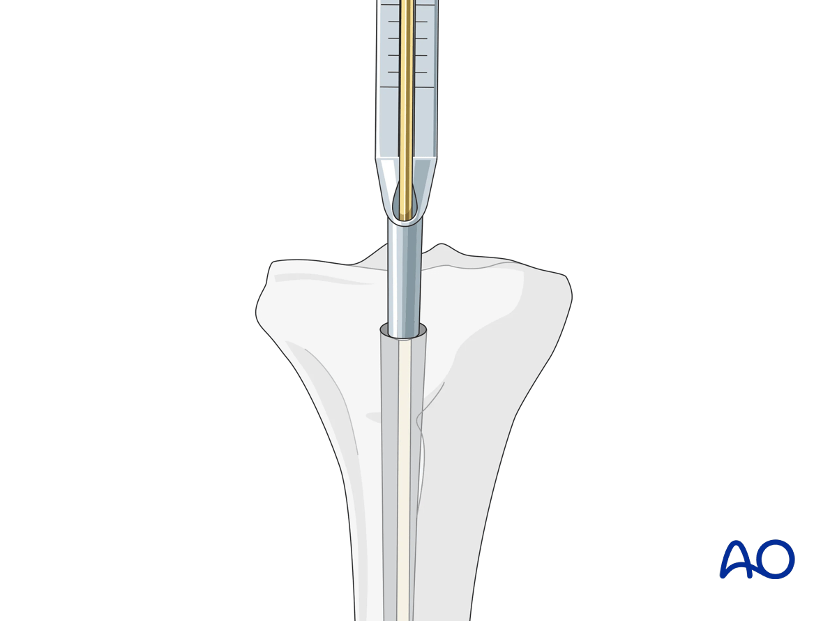
Determination of length using a depth gauge
All intramedullary nailing sets come with a depth gauge that is slid over the guide wire to determine the length of the nail to be inserted. X-ray imaging is used to confirm proper length.
If there are issues with using the depth gauge, alternative techniques to determine nail length are described below.
Determination of length using a second guide wire
The correct length of the nail can be determined by comparing a second guide wire of the same length to the one that has been inserted.
The correct placement of the guide wire in the distal canal should be assessed via image intensifier.
The tip of the second guide wire must be positioned at the entry point in the bone.
Measure the difference in length between the two wires (a). This difference represents the proper nail length (b), see illustration.
It is always advisable to double-check the measured length by comparison with the uninjured leg.

Determination of length using a radiographic ruler
Alternatively, a radiographic ruler may be used.
The tip of the ruler should be positioned where the distal end of the nail is intended to lie. Nail length is determined by the position of the nail entry point.

Determination of diameter
Nail diameter may be determined from the size of the last reamer used. The nail diameter is typically 1–1.5 mm smaller than the largest reamer used. Alternatively, a radiographic ruler may be used. It is important to measure the medullary diameter at the mid portion of the bone, which represents the narrowest segment of the medullary canal.
The inner cortical edge should touch the inner numbered disk of the ruler aperture. In the illustration an inner cortical diameter of 14 mm is shown. In this case, a 12.5 mm or 13 mm nail would be used.

7. Nail insertion
An appropriately sized nail is mounted on the introduction handle, which normally incorporates the guides for proximal locking.
If the nailing system has different implants for left and right sides, ensure the correct implant is selected, and the introducer is assembled correctly to ensure proper positioning of the nail.

If a guide wire is used, slide the nail over the guide wire and introduce it into the bone. Ideally the nail can be pushed down with twisting movements, but in practice some hammering may be needed.
The nail is inserted under x-ray control, with particular care being taken as the distal end of the nail passes through the fracture site.
Care must be taken not to create a new fracture, particularly in osteoporotic bone.

Make sure the nail is fully seated in the planned position. Depending on the bone and the nail, the position may be determined by the planned screw insertion, eg, into the femoral or humeral head.
In general, the end of the nail should be flush with the surface of the bone or should lie just under the surface.

8. Locking
The guide wire must be removed before locking can be started.

Proximal locking
Proximal locking is normally performed using the guide attached to the nail.

Distal locking
As the nail has a tendency to deform slightly as it is inserted, guides attached to the proximal end are not accurate enough for distal locking.
Distal locking is usually performed under x-ray control.

The central ray of the fluoroscope must pass through the locking hole so that its image is perfectly round and centered on the display screen. This confirms that the central ray is perpendicular to the nail.

With the leg and fluoroscope properly positioned, an incision is made with radiographic guidance over the selected locking hole. Then the soft tissues are bluntly spread.

The drill tip is positioned over the center of the locking hole.

The drill tip must be aligned with the fluoroscopic central ray. The drill is then advanced through the near tibial cortex, the locking hole in the nail, and the far tibial cortex. Its position is confirmed radiographically. If correct, screw length is measured, the appropriate screw is inserted, and its proper placement is confirmed radiographically.

Displacement
Interactive 3D animationIn more proximal or distal fractures, there is a higher tendency for angular displacement to occur. This 3D model shows a fracture in which the metaphysis does not provide much support for the nail, and there is a tendency for translational displacement.
If only parallel screws are used for locking, a small metaphyseal segment may displace along the screw axis. Screws should therefore be inserted in different axes, if the design of the nail allows, to enhance fixation. This is shown in the panel on the right.
An alternative to multiaxial interlocking screws is to use blocking screws (Poller screws) adjacent to the nail. Poller screws are used to block the movement of the bone segment around the nail. Screws placed adjacent to the nail can prevent translation as they decrease the width of the intramedullary canal, particularly in the metaphysis. They force the nail into the center of the medullary cavity and increase the stiffness of the bone-implant construct. They can be used to narrow the diameter of the medullary canal to prevent deformity in the coronal plane. The screw is placed perpendicular to the direction in which the fracture might displace, on the convex side of the anticipated deformity. As such, Poller screws can be used for alignment, stabilization and manipulation.
In the panel on the left, the screw counteracts the displacement of the fracture. In the panel on the right, the screw is incorrectly placed and cannot prevent displacement of the fracture.
The panel on the left shows a Poller screw being used to guide a nail into the center of the medulla. The panel on the right shows a nail being inserted into the medulla without the assistance of a Poller screw.
9. Nail end cap
Most modern nailing systems have nail end caps. These help to reduce bony ingrowth into the nail. If the top of the nail is seated well below the surface of the bone, a longer nail end cap should be used if available. This will mean that less bone needs to be cut away to uncover the nail end cap if the nail is subsequently removed.

10. Nail removal
It is generally not necessary to remove IM nails unless patients are symptomatic.
Unless there is an indication for urgent removal of the nail, it should not be removed until the fracture has definitely united.
Remove any bone that has grown over the top of the nail with an osteotome. It may be helpful to have imaging available for this procedure.

The nail end cap is removed prior to attachment of the extraction device.

The extraction device should be attached before removing the locking screws.

The locking screws are then removed, and the nail extracted.

11. Removal of broken nail
Various techniques have been developed that allow the removal of broken nails with specialized instruments.
If such instruments are not available, the following simple technique can be employed using guide wires.
If the nail is hollow, remove all locking screws.

It should be possible to pass an olive-tipped guide wire down to and through the nail tip.

One or more straight guide wires are then also passed out through the tip of the nail. This should block the olive-tipped guide wire, preventing it from reentering the nail.
Some trial and error may be needed to determine the correct size of the olive-tipped guide wire.

Once the olive-tipped guide wire is blocked, a T-handle chuck may be attached to the olive-tipped guide wire and the nail backed out using a hammer.


