Ring fixation
1. Introduction
A ring fixation system can be used to stabilize proximal tibia fractures.
This method is indicated for:
- Open and closed A and C type proximal tibia fractures
- Adjunct to internal fixation in complex fractures
This method is contraindicated for:
- Non-compliant patients
- Situations where there are problems with performing postoperative care
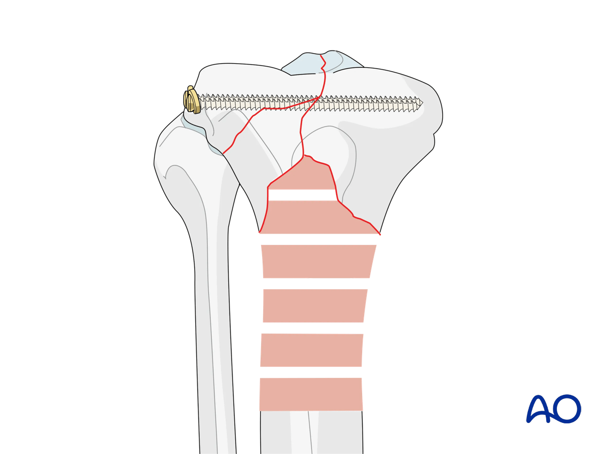
The mounting of a ring fixation system for a complete simple articular fracture with fragmentary metaphyseal components (41.C2.2) is shown here.
The ring system must be planned and mounted for optimal pin and screw insertion within the prescribed safe zones.
In addition to complete radiographs of the limb, a CT scan should be obtained to allow complete preoperative planning of the entire articular injury. The CT scan is usually done after temporary stabilization has been achieved with a spanning damage control fixator.
2. Patient positioning
The patient is placed in a supine position, with the leg elevated above the knee and at the ankle, allowing an unobstructed approach to the proximal tibia.

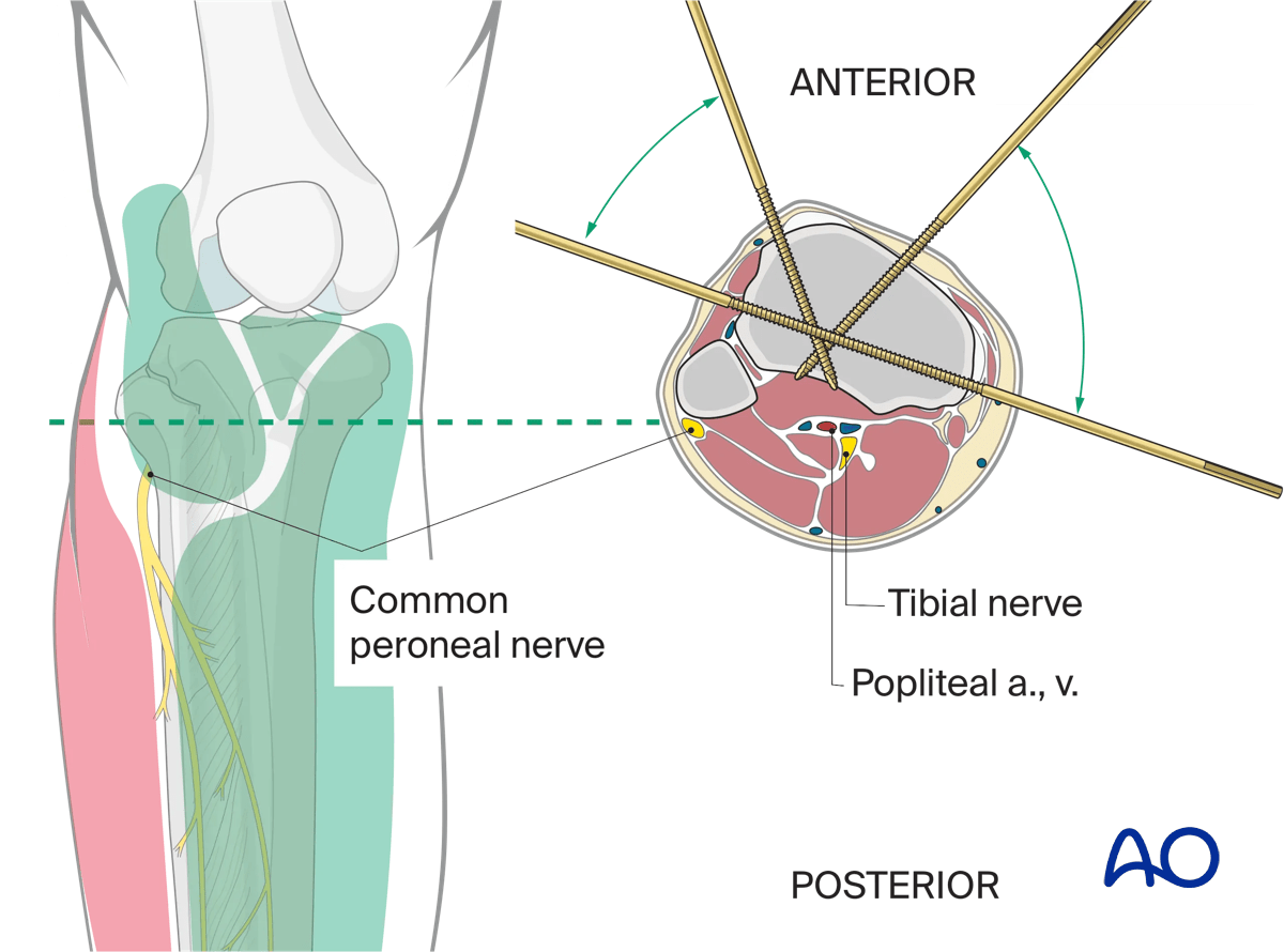
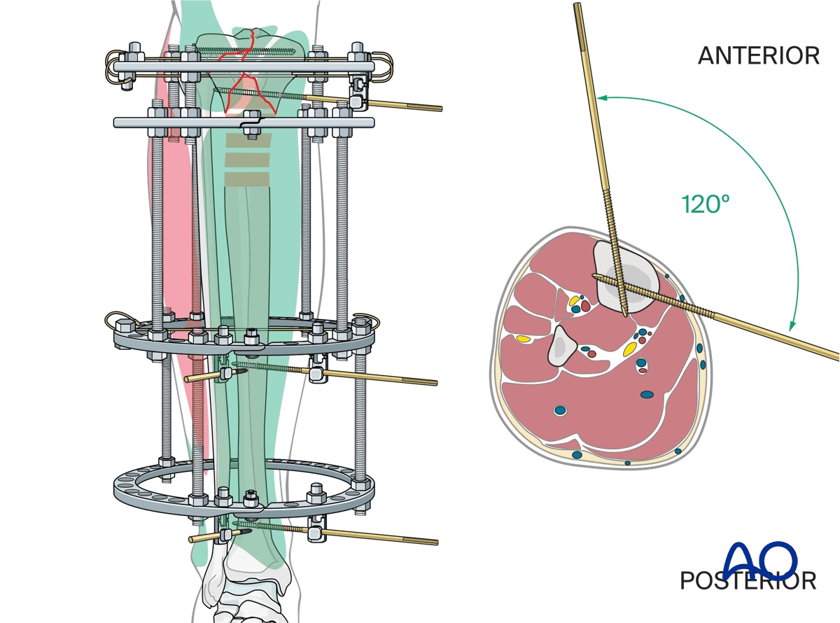
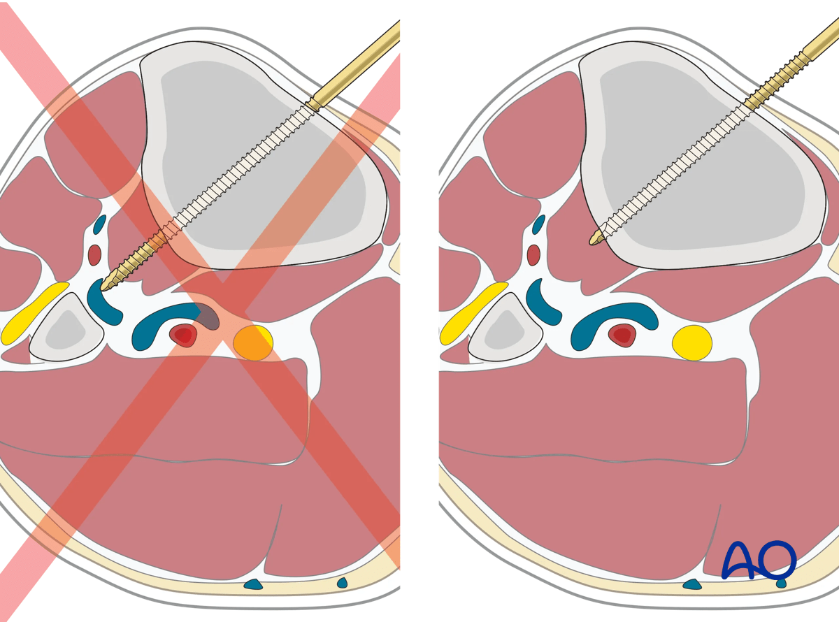
3. Surgical safe zones for wire and pin insertion
It is recommended that an inexperienced surgeon consult a cross-sectional anatomy atlas preoperatively.
Information on safe insertion of wires and pins can be found here:
4. Frame assembly
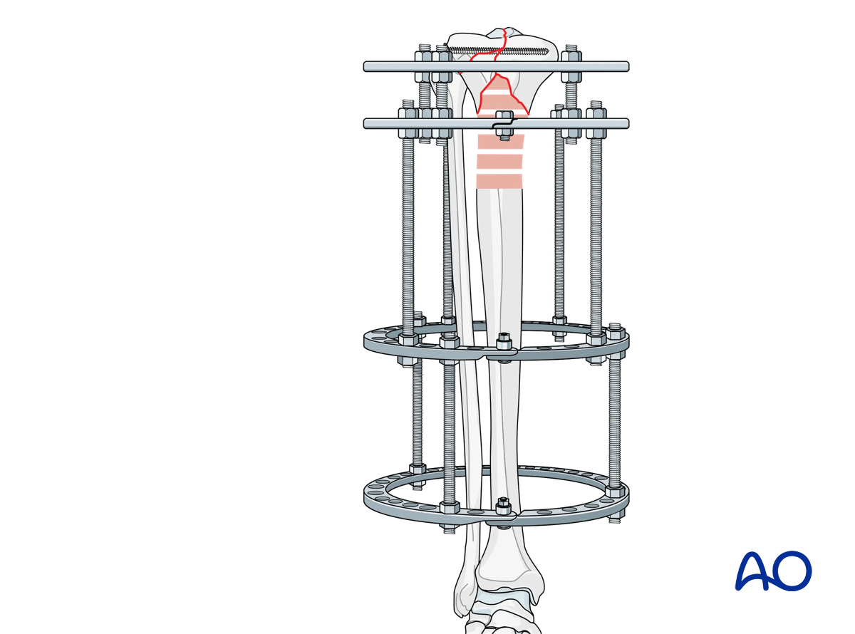
A full two ring block is assembled for the diaphyseal portion. The rings should span the intact bone segment beneath the zone of comminution and be connected by three or four threaded rods.
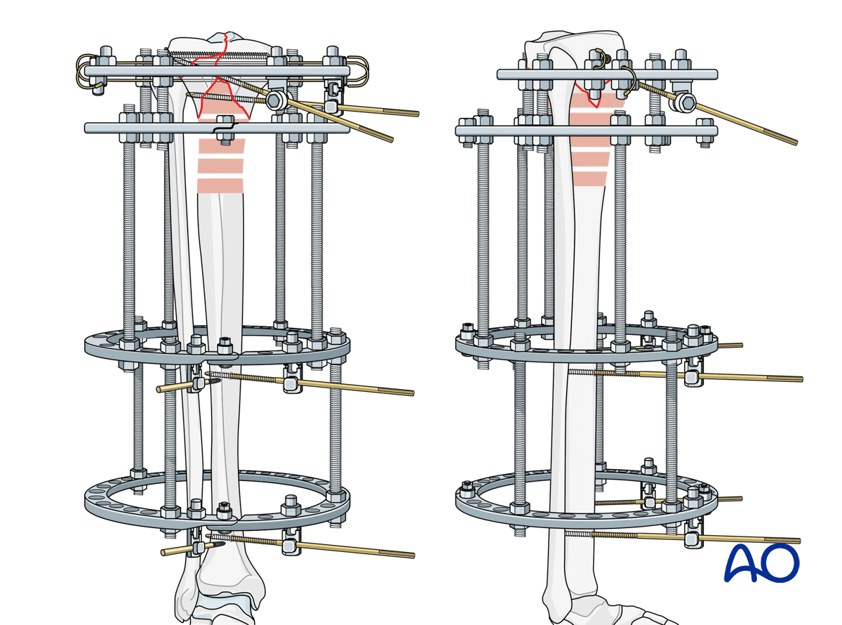
Proximal fixation at the fracture is through a single 5/8 ring. In some ring fixation systems, a second full ring placed immediately distal to the 5/8 ring may be necessary for appropriate stability. This construct is illustrated here.
The size of the rings assembled are chosen to optimally accommodate the lower leg anatomy, allowing for post-operative swelling, patient comfort, and cleaning and disinfection of the pins.
Connections between the proximal ring block and the diaphyseal ring block should be via a separate set of threaded rods, not an extension of the ring block rods.
5. Fracture fixation
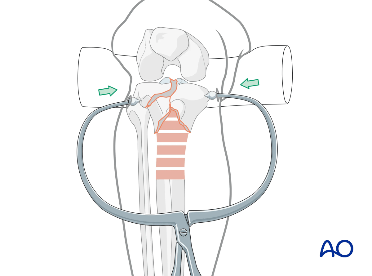
In general, reduction and stabilization of this simple articular fracture is performed prior to, and independent of, the ring fixator.
K-wires and a fracture reduction clamp placed percutaneously under fluoroscopic guidance can often achieve appropriate reduction of the articular surface. In some cases, open reduction may be required based on the preoperative CT scan.
The need for possible repair of the meniscus (either arthroscopically or open) should be assessed.
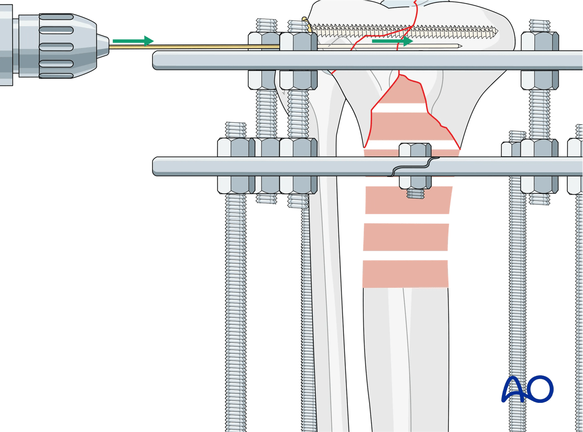
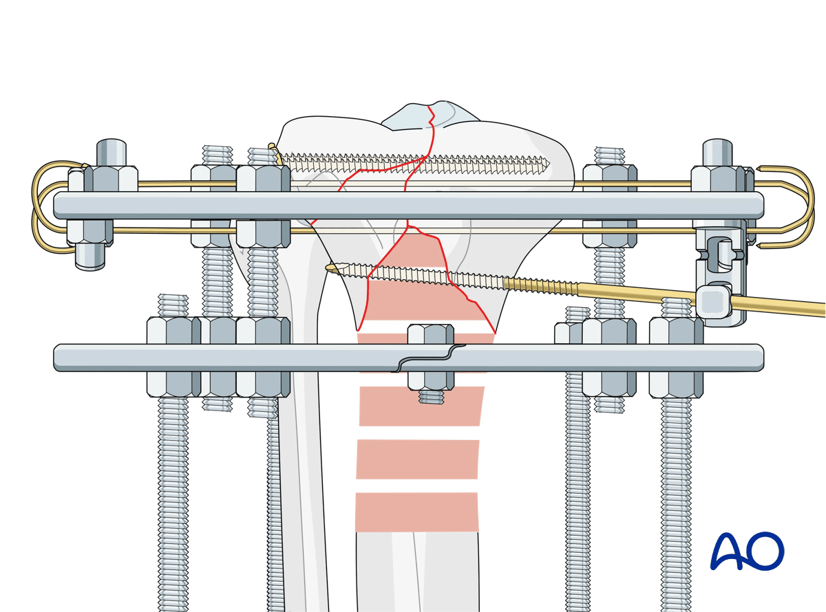
For simple articular fractures two 3.5 mm lag screws placed close to the articular surface may be sufficient for fracture fixation.
The two ring fixation blocks are assembled. The size of the rings assembled are chosen to optimally accommodate the lower leg anatomy, allowing for post-operative swelling, patient comfort, and cleaning and disinfection of the pins.
The two ring blocks are positioned on the tibia.
Positioning of the two ring blocks over the tibia separately is preferred as this allows the preassembled ring blocks to be passed over the leg. The planned position of the two ring blocks aims to provide optimal stability.
A temporary positioning wire can be placed from lateral to medial in the frontal plane perpendicular to the tibial shaft, off the middle ring for initial stabilization.
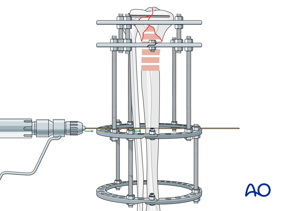
The diaphyseal fixation block should be placed parallel to the tibial shaft in both AP and lateral views, optimizing soft-tissue clearance.
Fixation of the diaphyseal fixation block is then completed with the addition of two Schanz screws off each ring, respecting anatomic safe zones. Each ring should have two Schanz screws in a multiplanar orientation for maximum stability.
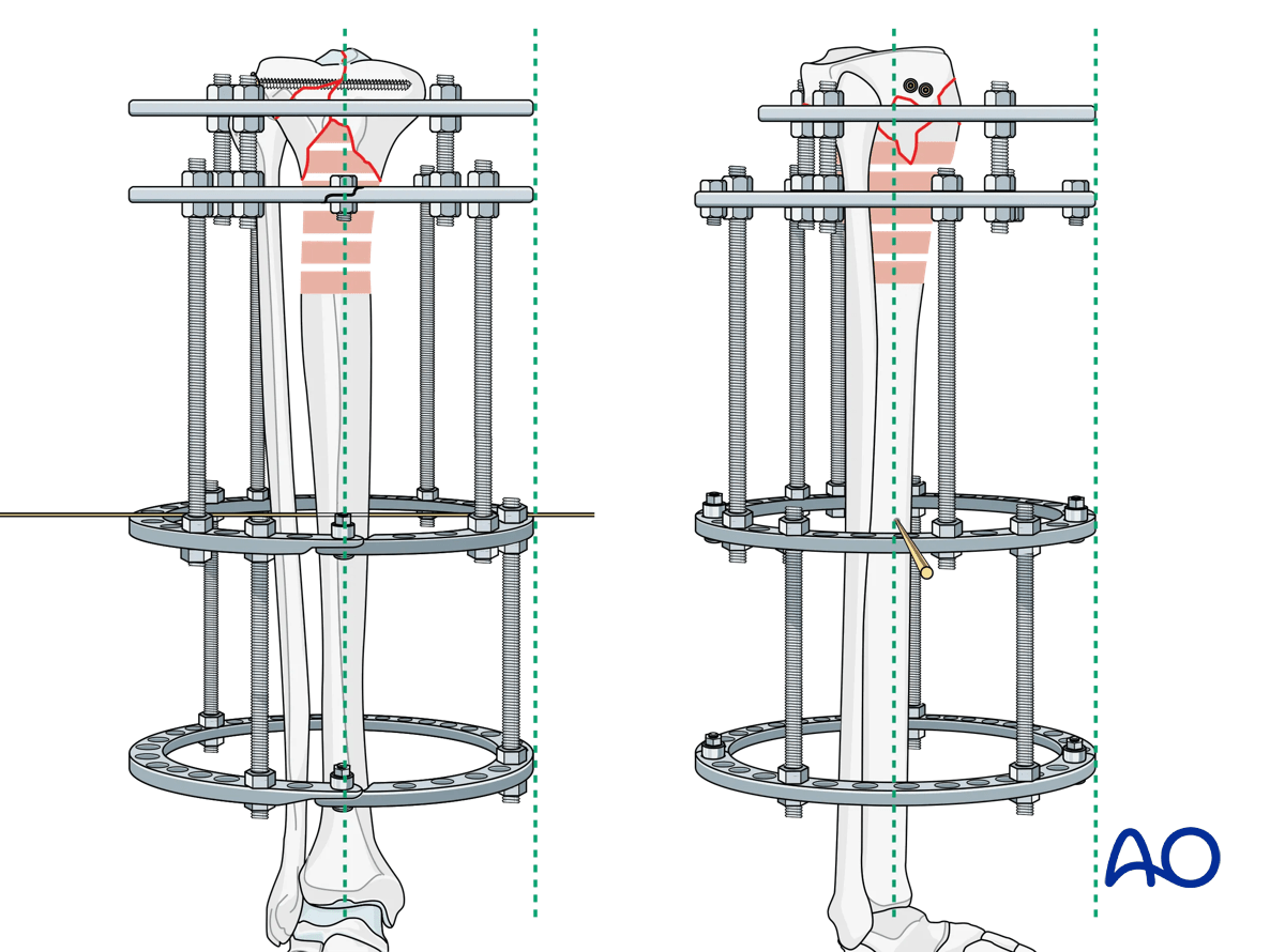
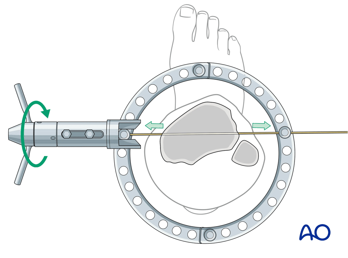
A smooth wire is then placed in the frontal plane from lateral to medial, orthogonal to the long axis of the tibia approximately 1.5–2 cm distal to the articular surface and distal to the lag screws. The articular ring is then positioned at the level of the wire by lengthening or shortening the threaded rods as needed. Care should be taken to check axial alignment of the articular block in both AP and lateral views.
The wire is then secured to the articular ring and tensioned. Care should be taken at this point to assess and correct varus-valgus alignment of the articular block with washers on the reference wire.
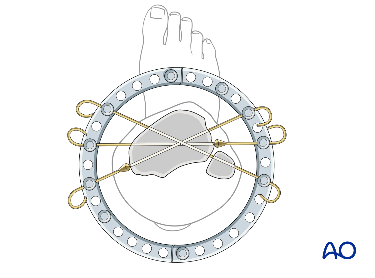
It is important to evaluate the sagittal alignment in the lateral image at this point to correct any flexion/extension deformities. Additional fixation of the articular block is via a pair of olive wires from either side of the proximal ring as widely divergent as the soft tissue will allow. This pair of olive wires will control translational movement of the proximal segment.
Teaching video
Further information on the use of olive reduction wires can be found in this video.
Depending on the length of the proximal segment it may be possible to place a Schanz screw into the articular bone block either medially or laterally.
Stability of the proximal tibial segment requires a minimum of four wires or three wires and one Schanz screw.
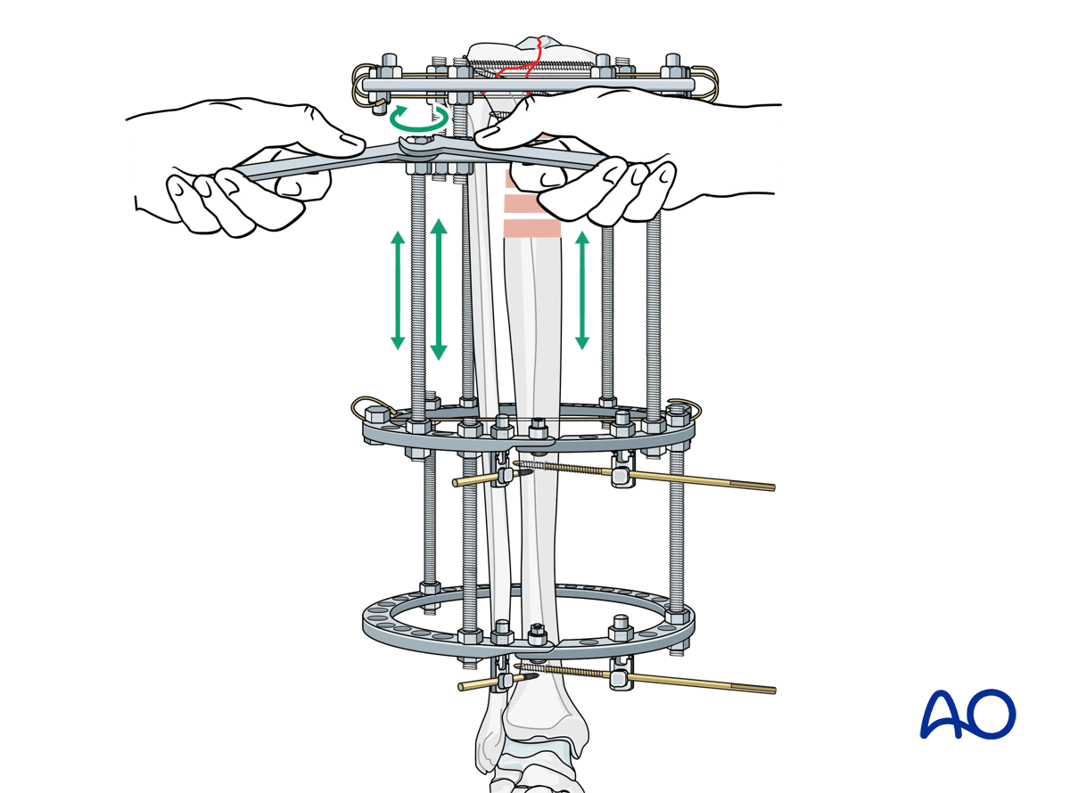
The metaphyseal comminution can now be lengthened or compressed via the threaded rods connecting the proximal two rings, and this relationship should be assessed.
6. Review of ring fixation key elements
The following elements should be reviewed:
- Anatomic reduction of the articular surface
- Lag screw fixation of the articular surface
- Stable diaphyseal fixation block
- Stable fixation of the articular segment
- Appropriate axial alignment of the articular segment
- Fracture compression or distraction as needed
7. Options for Schanz screw placement
Schanz pins in the tibia are generally placed from the medial side (anteromedially, direct medial, or posteromedial). Pin divergence within the safe zone helps to optimize biomechanical stability of the frame.
Predrilling prior to placement of Schanz screws is recommended in order to minimize thermal necrosis of the bone.
In general, 5 mm or 6 mm blunt tip Schanz screws are used in the tibia of adult patients. Schanz screws are available in uncoated, and hydroxyapatite (HA) coated versions. In clinical scenarios in which the frame is expected to be on for an extended period of time HA coated pins should be considered as they have been shown to decrease infection and loosening rates.
Predrilling is performed with the recommended drill size and drill sleeves, with attention to water cooling. Schanz screws should be manually inserted.
The exact method for mounting a Schanz screw will depend on the ring fixation system being used. In general, Schanz screws can be mounted directly on a ring, at a fixed distance off a ring, and angulated off a ring.
When angulating a pin off a ring 30° from the ring axis is optimal.
One type of Schanz screw mounting method is shown here.
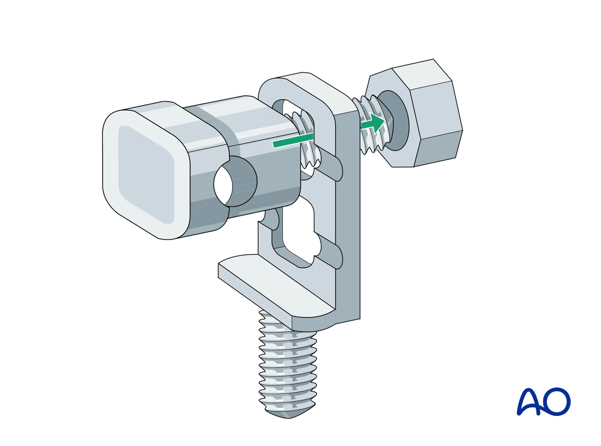
Schanz screw mounting with multiparallel pin clamp
The eye bolt fits into the square hole and the groove of the multiparallel pin mount in only one direction.
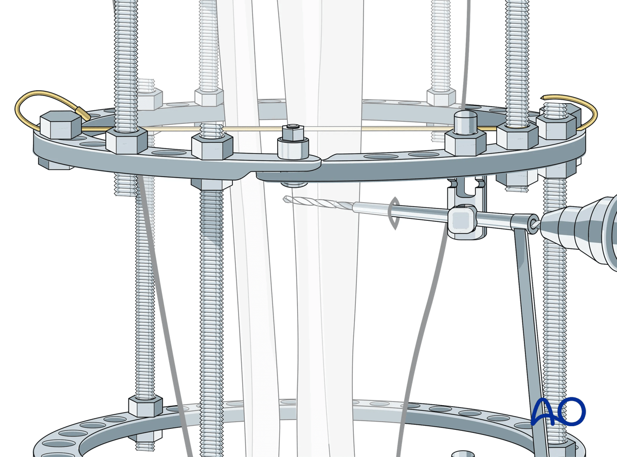
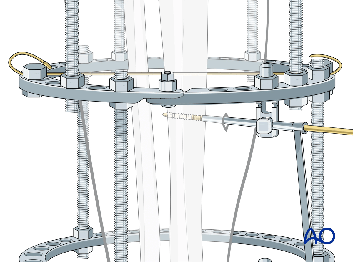
The steps for Schanz screw insertion are as follows:
Once the chosen location for the Schanz screw is determined, the assembled eye bolt and the selected multiparallel pin clamp are secured to the ring.
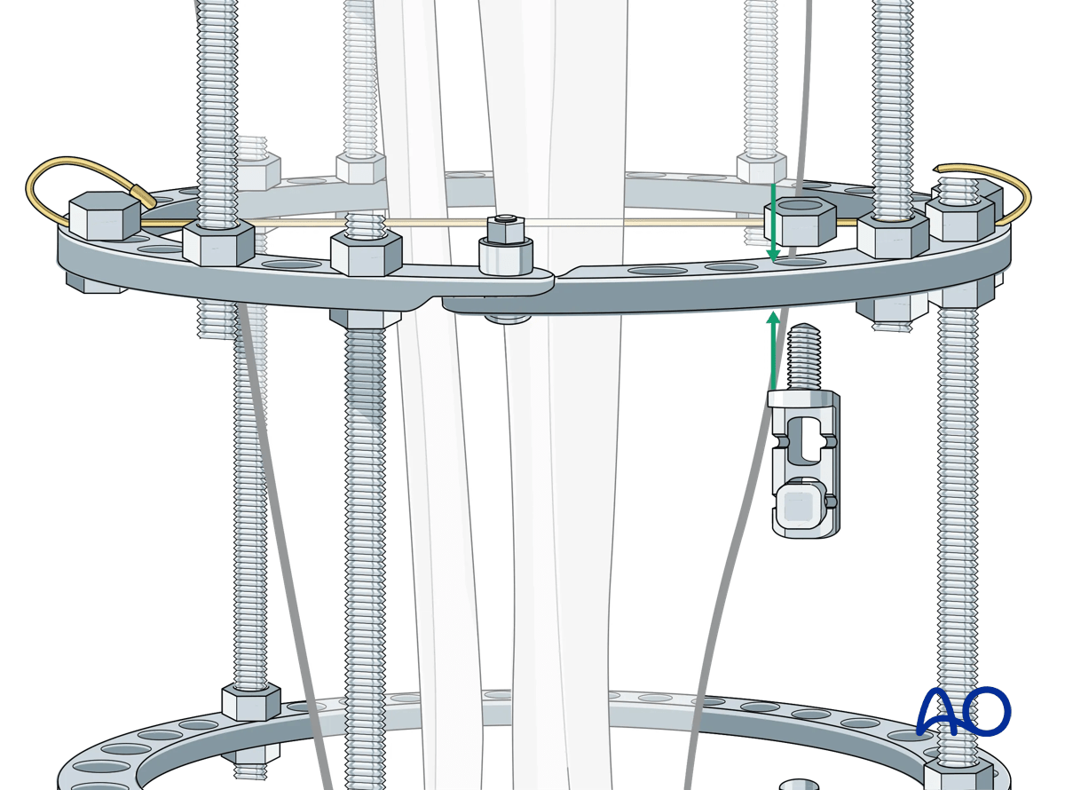
The triple drill sleeve is inserted through the eye bolt. To do this the nut holding the eye bolt needs to be loosened.
It is imperative that Schanz screws be bicortical.
A skin incision is made at the skin contact point.
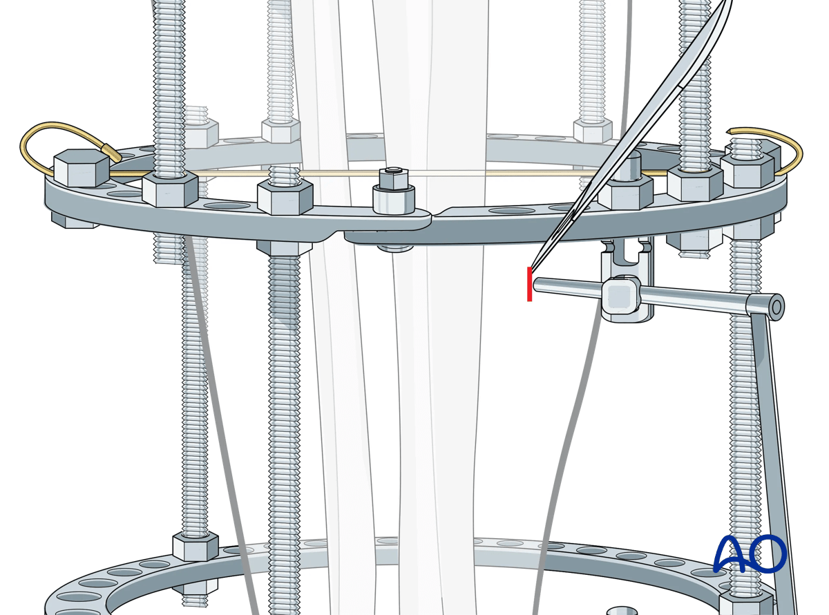
The soft tissue is spread down to bone using a hemostat. The triple sleeve is then passed to the bone surface. Fluoroscopic confirmation of position is recommended to avoid a unicortical pin placement.
Then the inner trocar is removed, and the drill is introduced and drilled across both cortices. Attention is paid to irrigation in order to avoid thermal necrosis. The desired thread length of the Schanz pin is chosen from the calibrated drill.
The drill and the innermost trocar are removed and the Schanz screw is placed manually.
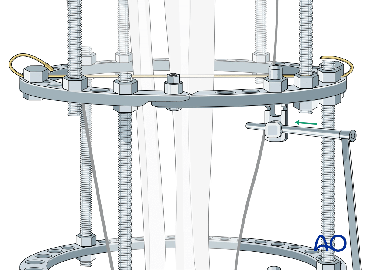
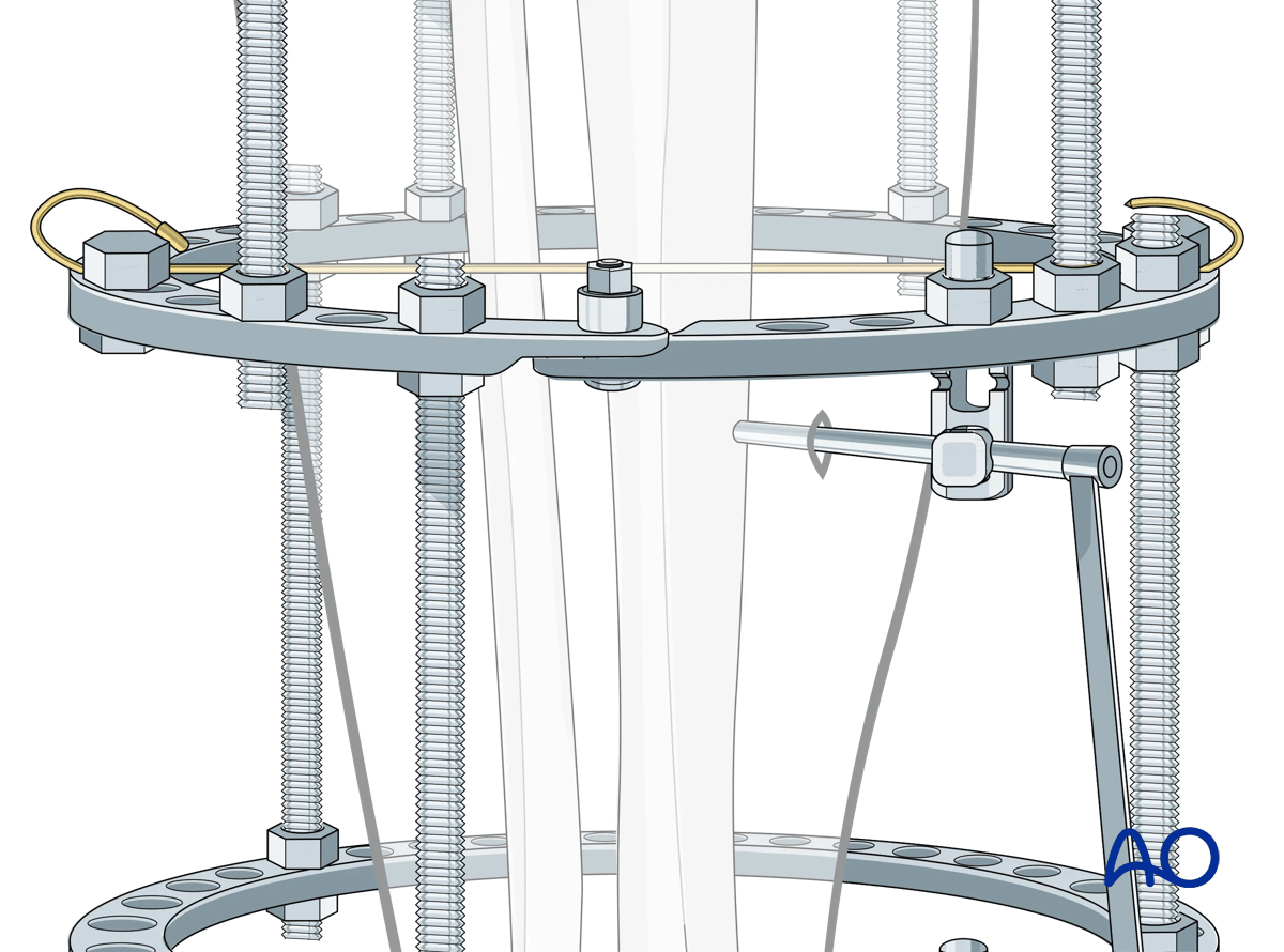
The outer trocar is then removed and the nut securing the eye bolt is tightened. The nut securing the multiparallel pin clamp should also be tightened. This can be accomplished with two wrenches, or alternatively the pin can be held manually and used to create counter-torque during these maneuvers.
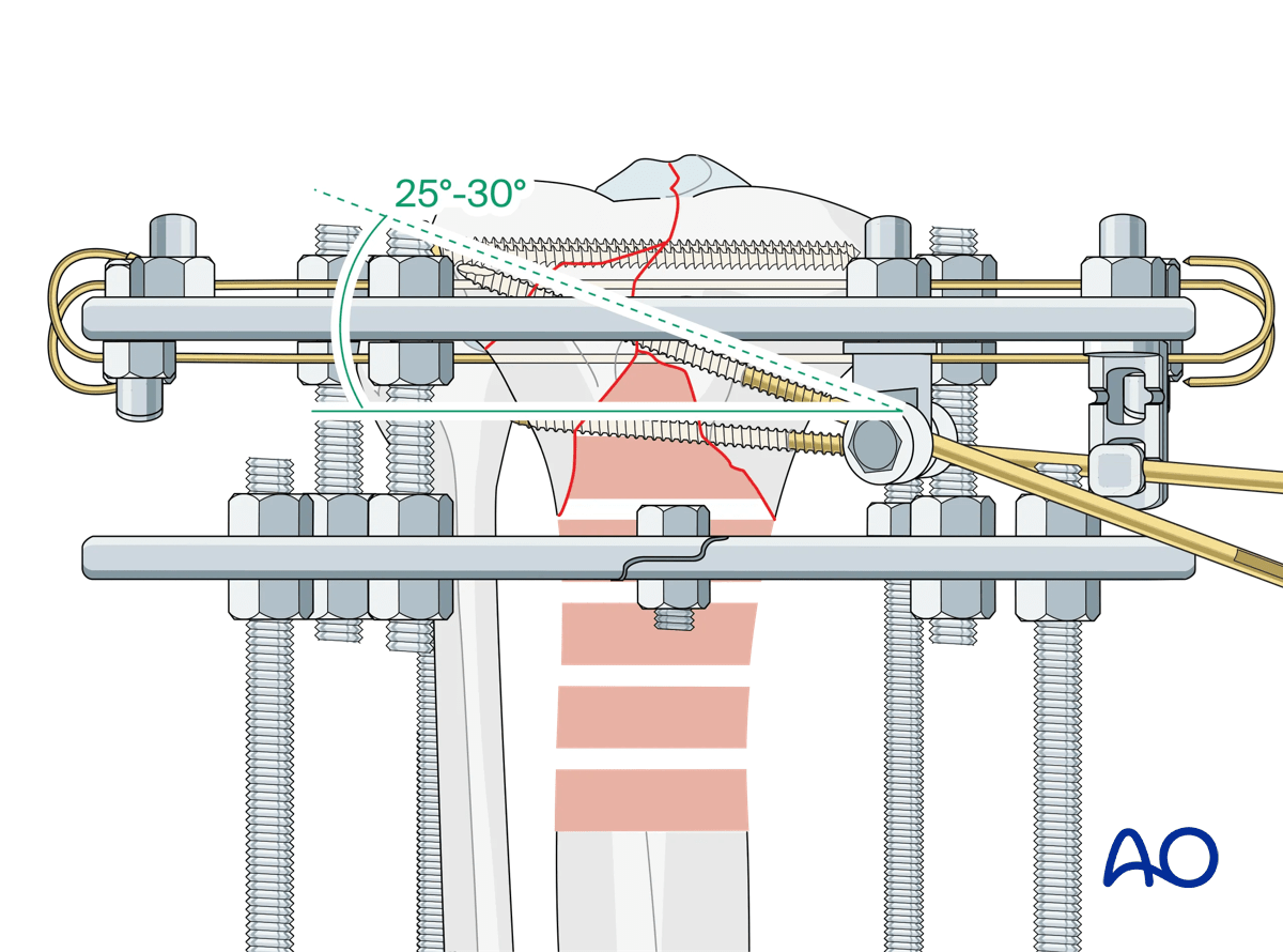
Placement of additional Schanz screws
Additional Schanz screws should be placed respecting the following considerations:
- Anatomic safe zones
- Multi-planar placement to optimize biomechanics
When placing an angled pin off a ring, optimal biomechanics are achieved when the angle is between 25° and 30°.
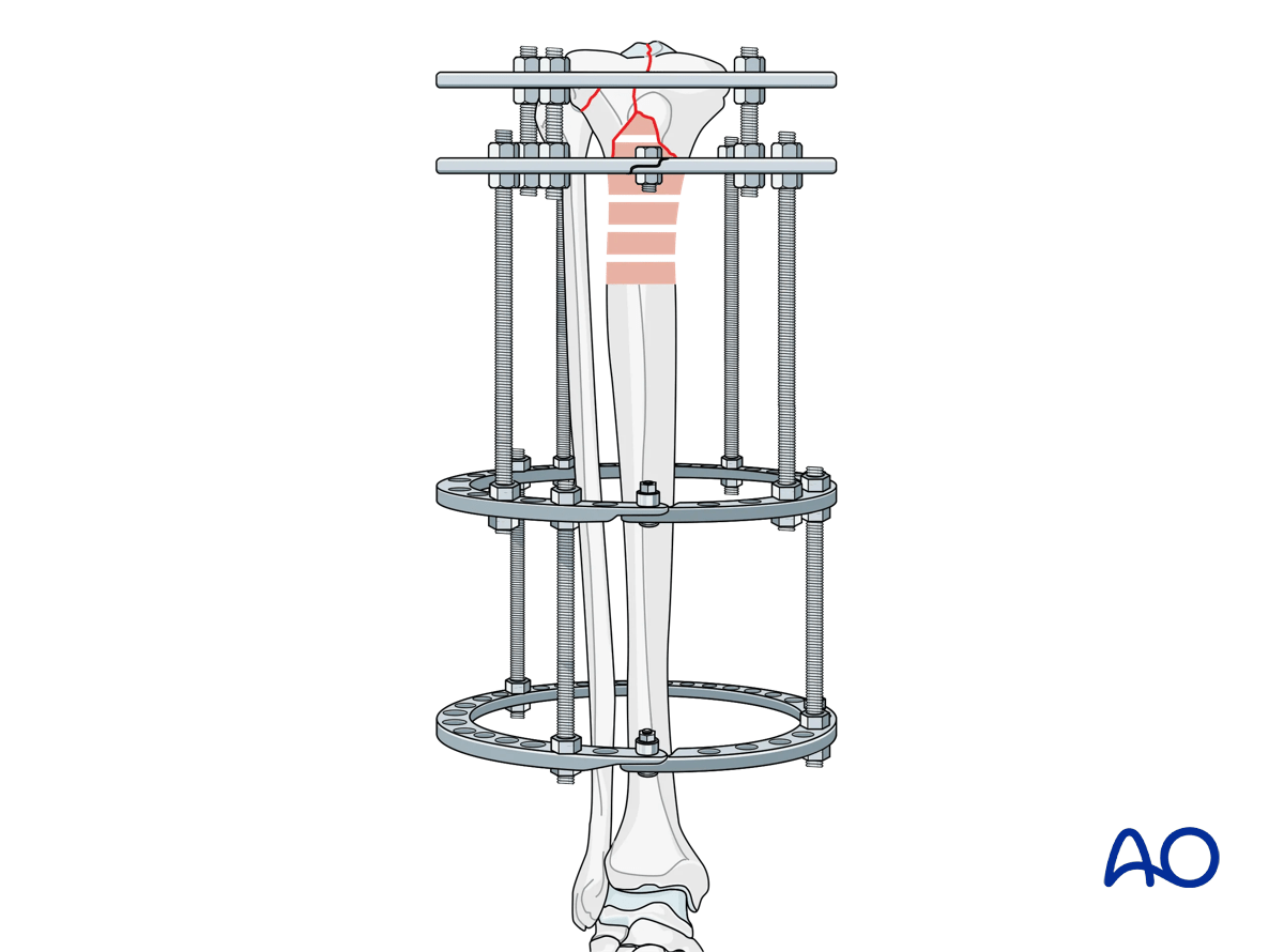
8. Completion of frame assembly
The number of connecting rods used depends on the specific external fixation system. If connecting elements are 6 mm in diameter it is recommended to use four rods between all rings. If 8 mm in diameter then three rods are sufficient.
This illustration shows that appropriate stability has been achieved.
Consideration should be given to removing the temporary positioning wires in the diaphysis at the conclusion of the case as these may be painful during weight bearing.
All threaded connections should be checked and tightened.
This illustration shows an 8 mm external fixation system.
9. Case example
The clinical case shows a 45-year-old man injured in a motorcycle accident, sustaining a closed injury of his proximal tibia of the type 41.C2.2. Initial treatment consisted of placement of a temporary spanning frame and CT scanning for preoperative planning. Forty-eight hours later definitive fixation was performed.
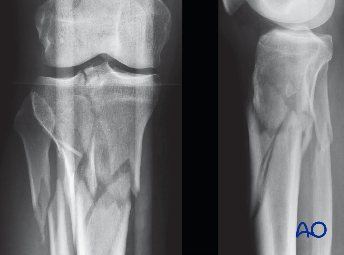
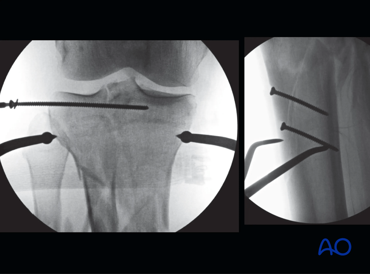
The articular surface was reduced percutaneously with a clamp and then stabilized with a 3.5 mm lag screw positioned close to the joint to leave room for olive wires for the ring fixator. The bone fragment containing the tibial tubercle was also fixed to the intact shaft with two 3.5 mm lag screws.
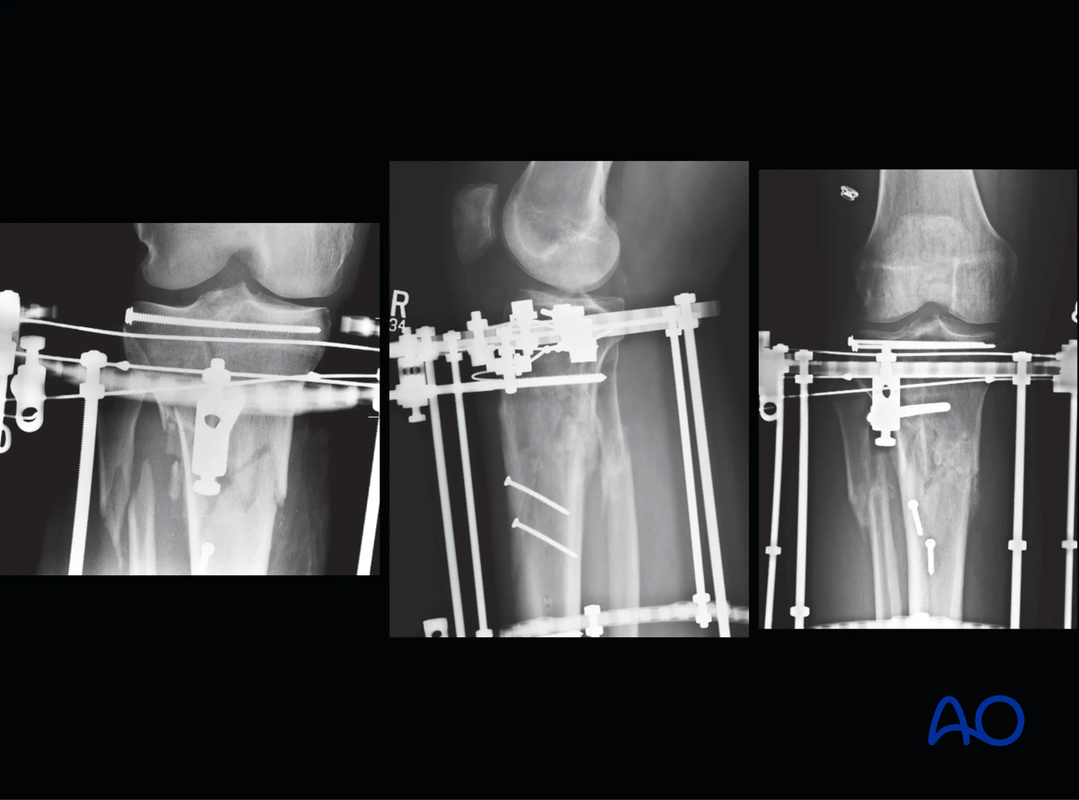
A three-ring frame was assembled using two full rings in the diaphysis and a 5/8 ring at the joint. The diaphyseal fixation was two Schanz screws off each ring and three wires and one Schanz screw in the reassembled articular block. Two of the wires proximally were placed as opposing olive wires.
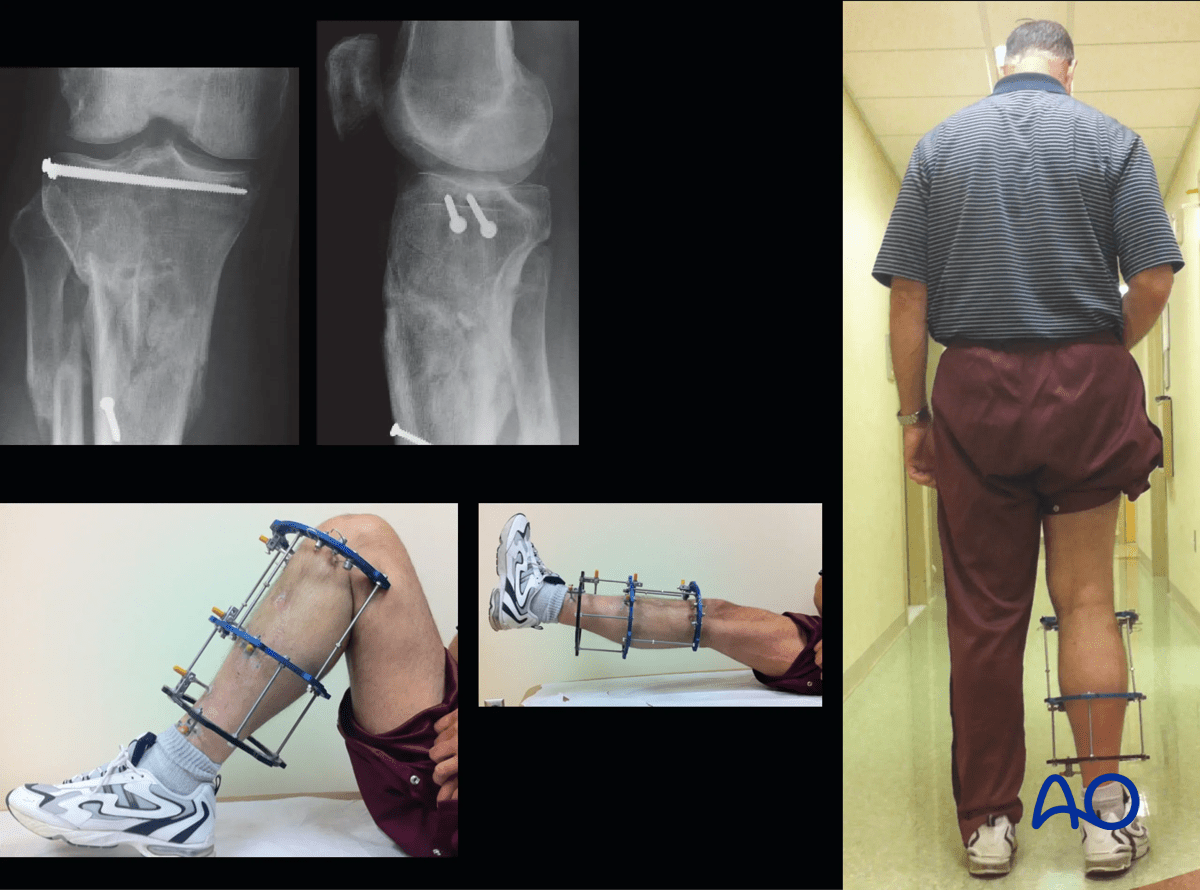
The patient was allowed immediate active and passive motion of the range of knee. At eight weeks the patient was allowed weight bearing.
The frame was removed at 16 weeks after fracture healing.
10. Aftercare
Pin site care
Proper pin insertionTo prevent postoperative complications, pin insertion technique is as important as the pin care protocol:
- Correct placement of pins and wires (see safe zones) avoiding ligaments, nerves, and tendons, eg, anterior tibial tendon
- Correct insertion of pins (eg, trajectory, depth) avoiding heat necrosis
- Extending skin incisions to release soft-tissue tension around the pin insertion (see inspection and treatment of skin incisions)
- Creation of a mechanically stable frame will minimize pin-site motion
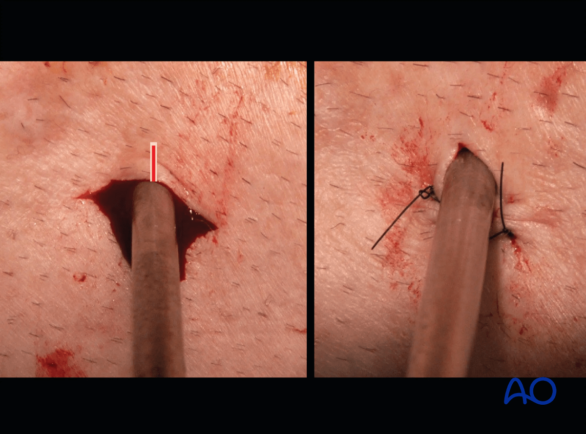
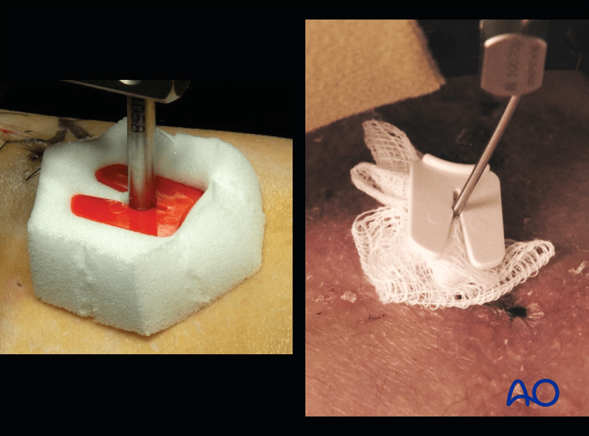
These images show the release of a pin to minimize skin tension. A releasing incision is made with a scalpel, as shown. After release, the left and right sides are sutured to create a tension-free closure.
Various aftercare protocols to prevent pin track infection have been established by experts worldwide. Therefore, no standard protocol for pin site care can be stated here. Nevertheless, the following points are recommended:
- Relative motion between pin and skin should be minimized as a general rule. This is particularly important in areas of thick tissue or significant soft-tissue movement.
- A compressive dressing that limits skin motion is useful, initially after frame placement, and continued for any pin exhibiting ongoing drainage.
- A daily shower with antibacterial soap is very useful after surgical incisions have healed.
- Pin insertion sites should be kept clean. Any crusts or exudates should be removed. The pins may be cleaned with saline and/or disinfectant solution/alcohol. The frequency of cleaning depends on the circumstances and varies from daily to weekly but should be done in moderation.
- Dressings are not usually necessary once pin drainage has ceased.
- Pin insertion sites need not be protected for showering or bathing with clean water.
- The patient or the care-giver should learn and apply the cleaning routine.
- Oral antibiotics are reserved for pin site infections.
These images provide examples of compressive dressings.
In case of pin/wire loosening or pin track infection, the following steps need to be taken:
- Rest and elevate limb
- Moist saline compress
- Oral antibiotic
- Wrap pin to control skin/pin motion
- Release any skin tension
For recalcitrant pin-site problems consider:
- Culture drainage and switch to organism-specific antibiotics
- IV antibiotics
- Checking x-ray for lucency
- Removal or exchange of pin
Mobilization
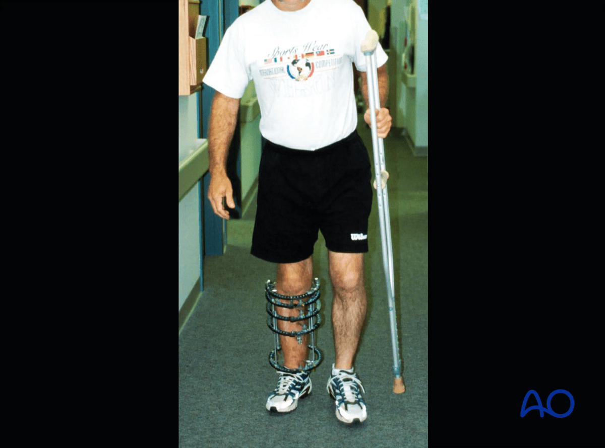
In most cases of ring fixation, stability is sufficient to allow weight bearing as tolerated. Exceptions to this include intraarticular fractures or significant soft tissue concerns. In these cases, weight bearing should be delayed until healing of the intraarticular fracture (8–12 weeks).
Joint range of motion should begin both actively and passively as soon as soft tissues allow. In the lower extremity the development of a knee flexion contraction and/or ankle equinus are significant concerns and should be monitored at every clinic visit.
Attention should be paid to DVT prophylaxis which will be determined on the specifics of the clinical scenario.
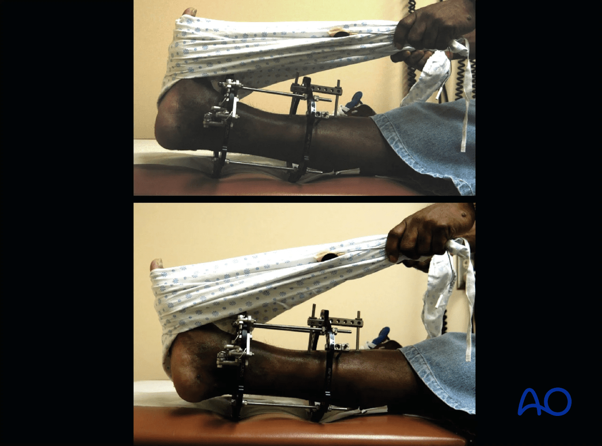
The two images show active and passive range of motion of the ankle in the frame.
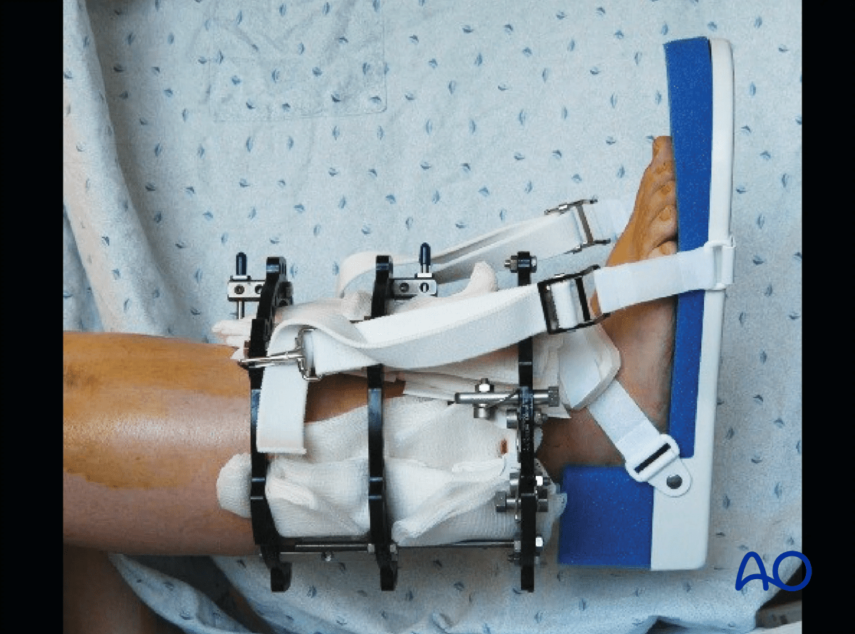
The image shows one method of static splinting of the ankle in the neutral position.
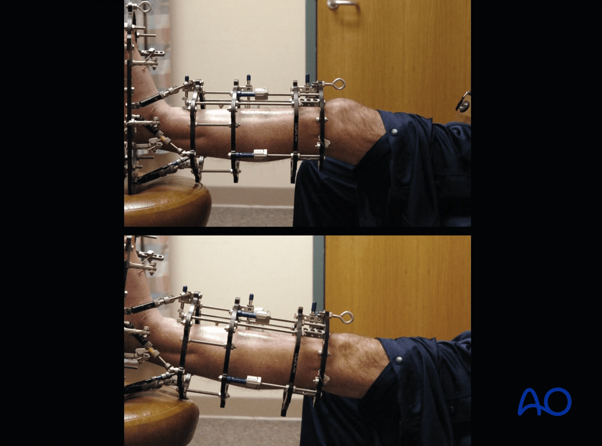
Patients should be taught terminal knee extension exercises. These images demonstrate terminal knee extension exercises in the frame. The prevention of a knee flexion contracture is of particular importance when treating proximal tibia fractures. This potential complication should be evaluated at every postoperative patient visit.
Follow up
The patient should be seen at two weeks after surgery for suture removal, and then every 2–4 weeks with radiographs to monitor fracture healing. At every clinic visit the frame should be inspected for pin problems, and frame loosening. The patient should be observed ambulating, and range of motion of adjacent joints should be examined.
Frame removal
The timing of frame removal is determined by a combination of the clinical scenario and radiographic evaluation of the fracture. In lower extremity applications the patient should be comfortably weight bearing in the frame as supporting evidence of fracture healing. Fracture healing should be visualized radiographically on three cortices. The clinical appearance of the pins is usually quite good at this point with minimal to no pin drainage. This observation confirms that the frame is offloaded because of healing of the bone.
The method of frame removal depends on the patient and the type of pins used. When hydroxyapatite (HA) coated pins have been used, frame removal will require sedation/anesthesia. In selected cases with non-HA coated pins, frame removal can be performed in the clinic.
Post frame removal care
Some form of external stabilization (fracture boot or cast) is recommended in the early period after frame removal (4–6 weeks). Pin sites will generally require dressing changes for 3–4 days. Weight bearing as tolerated is usually allowed immediately following frame removal. Showering should be allowed once all pin sites are dry.


