Sliding hip screw
1. General considerations
Introduction
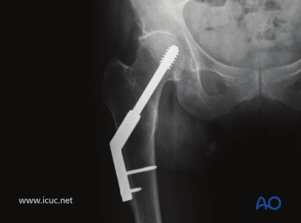
Because of the intrinsic stability of fractures with lesser trochanter attached to the distal fragment after reduction, most implants will be adequate to maintain reduction and result in uneventful healing. Simple extramedullary sliding devices like the dynamic hip screw (DHS) are the cheapest and most logical fixation choices.
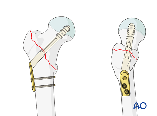
Throughout this treatment option illustrations of generic fracture patterns are shown, as four different types:
A) Unreduced fracture
B) Reduced fracture
C) Fracture reduced and fixed provisionally
D) Fracture fixed definitively
Closed vs open reduction
Fracture reduction should start with a closed attempt.
If manipulation does not lead to a satisfactory reduction, a percutaneous reduction technique should be performed.
The definitive decision for the treatment will be made after positioning the patient and an initial closed reduction. Since emergency department x-rays are often of suboptimal quality, verifying the preoperative diagnosis using image intensification is necessary.
Fractures with the lesser trochanter still attached to the femoral shaft are generally stable trochanteric fractures because, after anatomic reduction and internal fixation, there is little tendency for loss of reduction under physiological loading.
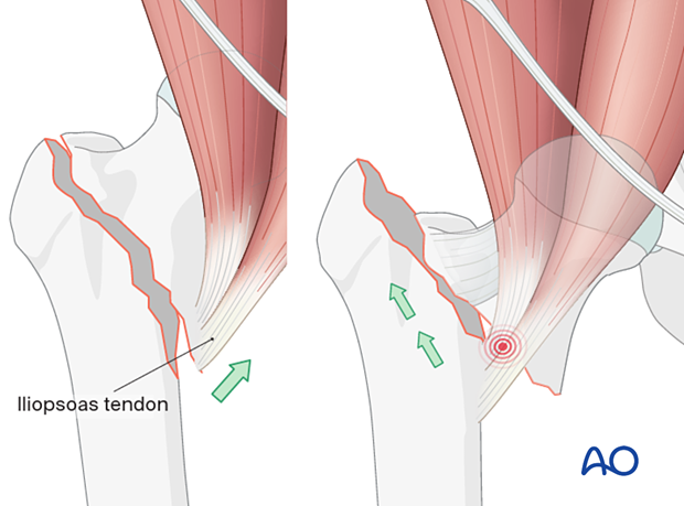
The pull of the iliopsoas muscle may flex and externally rotate the proximal fragment, and traction will not correct this displacement. In these cases, open reduction is often necessary.
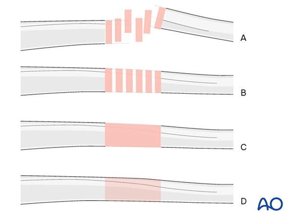
Superolateral displacement of the shaft (right illustration) after high-energy trauma is a sign of an irreducible intertrochanteric fracture and requires open reduction.
The displacement of the medial neck spike causes button-holing anteromedially through the iliofemoral ligament, anterior capsule, and iliopsoas.
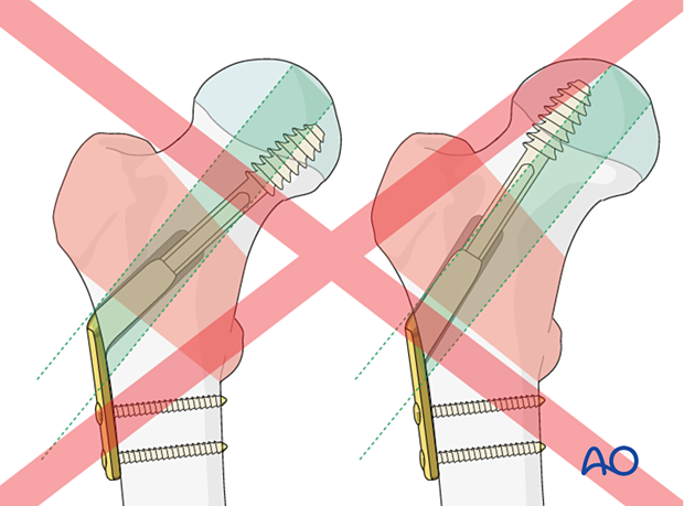
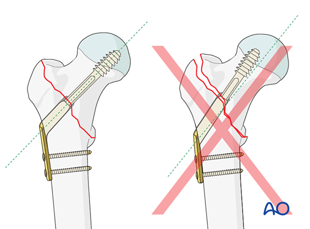
Correct position of lag screw or blade
The thread of the lag screw (or tip of the spiral blade) needs to end in the trabecular bone structures to gain enough purchase. Therefore, it is important that the lag screw comes to lie in the center of the head-neck axis or slightly inferior to it. This allows for increased depth of the screw.
Implant selection and preoperative planning
Spiral blade vs lag screwThere is not yet a clear indication of when to use a spiral blade and when a lag screw. It is, therefore, often surgeon’s preference.
In a young patient with hard bone, a blade is relatively contraindicated, and a screw should be used instead (with tapping).
In elderly patients, the use of a blade does compact the bone.
Generally, for pertrochanteric fractures with lesser trochanter attached to the distal fragment, a two-hole DHS plate is enough.
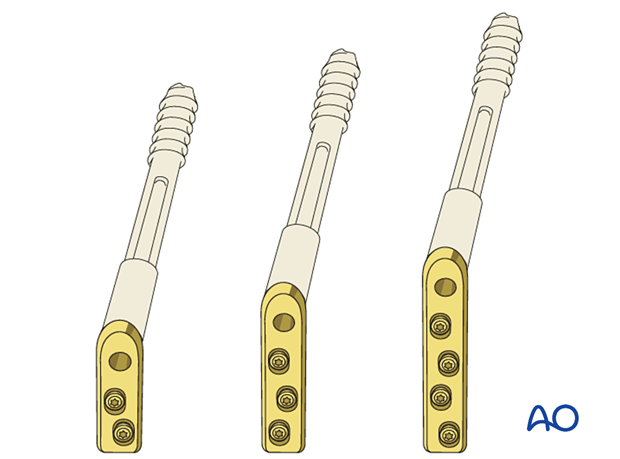
A plate with a short barrel (illustration on the right) may be used if the lag screw length is ≤ 75 mm to allow for sliding.
A short barrel should only be considered if its end would impinge dense cancellous bone in the head.
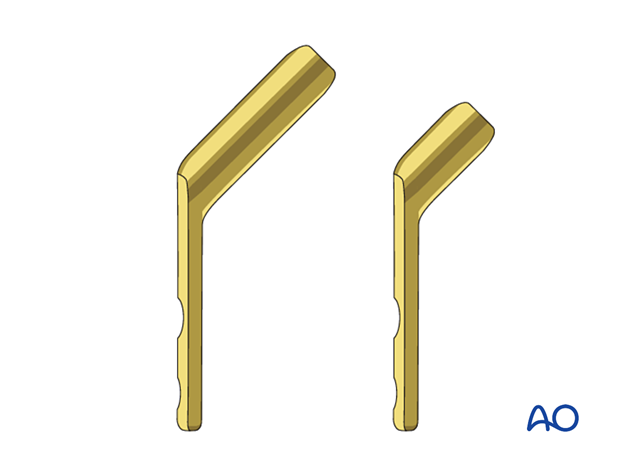
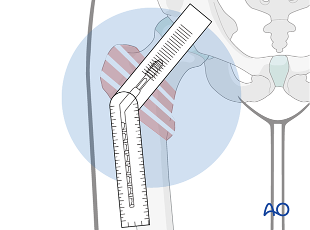
For proper insertion of the implant, determine the optimal neck-shaft angle on the basis of the contralateral intact proximal femur. This is usually 130° or 135° depending on the patient.
If this is not available due to previous hip-joint replacement or improper AP view with external rotation of the proximal femur, provisionally reduce the fracture before draping under traction and assess the reduction quality. If acceptable, measure the angle from the AP view after reduction.
AO teaching video
Femur, Proximal – Trochanteric Fractures – Stabilization Using the Dynamic Hip Screw (DHS) and a Demonstration Exercise Using DHS in Combination with the Universal Locking Trochanter Stabilizing Plate (ULTSP)
(26 minutes)
2. Patient preparation
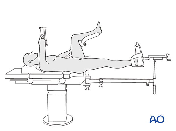
Position the patient supine on a fracture table either with the contralateral uninjured leg placed on a leg holder or in a scissors configuration.
For C-arm positioning to acquire optimal AP, lateral, and axial views, read the additional material on:
3. Reduction
Closed reduction
Closed reduction is usually achieved by:
- Pulling in the direction of the long axis of the leg to distract the fragments and regain length
- Adjustment of internal rotation of the femoral shaft ...
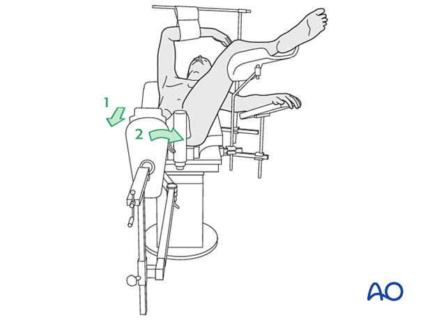
... until the patella is facing forward on an AP view of the knee joint
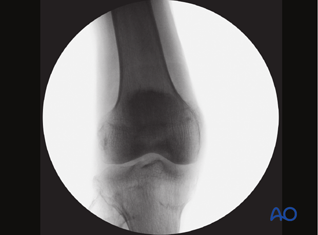
Check the reduction in both the AP and lateral view with an image intensifier.

Assessment of reduction quality
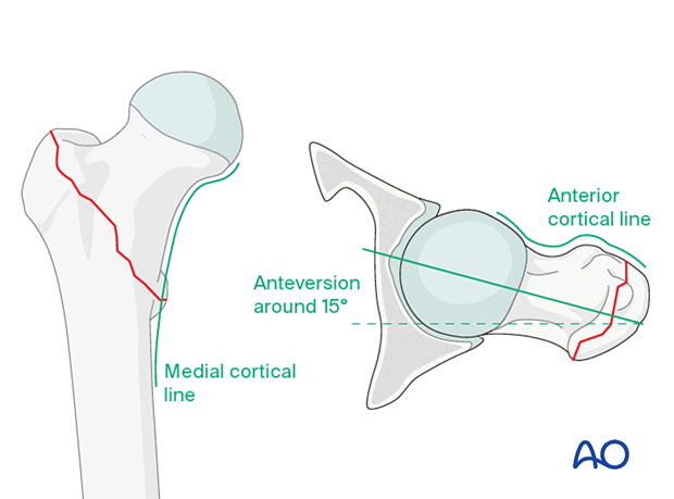
Read the fracture line on the image intensifier views. Identify gaps or increased density due to overlapping of fragments.
Follow the medial cortical line on the AP view and the anterior cortical line on the axial view. Identify any translational or angular malalignment.
Acceptable reduction quality shows the following patterns:
- No gap or increased density visible along the fracture line
In the AP view:
- Continuous medial cortical line
- No varus angulation
In the lateral view:
- Anteversion approximately 15°
- Continuous anterior cortical line
For more details, see the additional material on assessment of reduction quality.
Percutaneous reduction
If closed reduction is not satisfactory, carry out a percutaneous reduction technique.
Open reduction
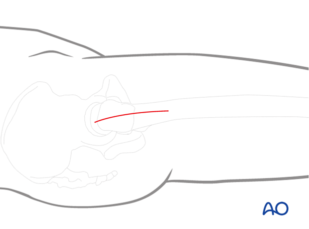
If closed reduction fails, carry out an open reduction through a lateral approach.
Enlarge the lateral incision as necessary by increasing its length and retracting the vastus lateralis anteriorly and medially. Direct visualization of the fracture site is usually unnecessary.
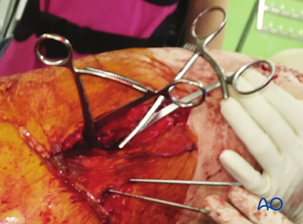
After clearing the fracture site from soft tissue, the reduction remains challenging, often requiring repositioning and the use of reduction forceps.
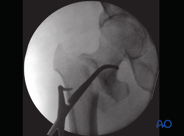
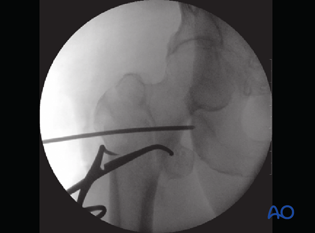
Insertion of a first K-wire to increase stability
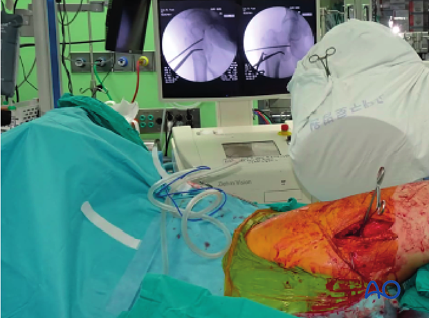
Clinical photograph showing C-arm position for lateral imaging
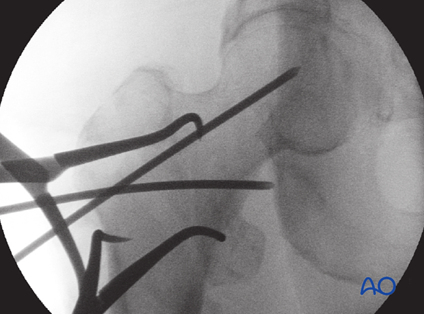
Final reduction is performed with two reduction forceps in different planes and K-wire stabilization.
Confirm acceptable reduction under image intensification.
4. Approach for implant insertion
If the reduction has been performed closed or percutaneous, perform a limited lateral approach with an incision large enough to insert the implant and cortical screws.
5. Guide-wire insertion
Insertion of antirotation wire
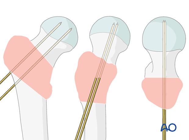
To avoid rotational displacement during screw insertion, place an antirotation wire parallel and proximal to the head-neck axis.
If a K-wire used for temporary fixation is in an appropriate position, this can be used instead.

Application of the aiming device
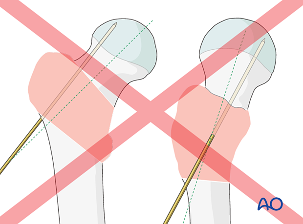
Place the appropriate aiming device so that the screw trajectory runs through the head-neck axis or parallel and slightly inferior to that on an AP view.
This ensures that the tip of the blade or lag-screw thread ends in the trabecular bone structures.
Check its position with the image intensifier in AP, lateral, and axial views. In all views, the trajectory should be in line with the head-neck axis.

Insertion of a guide wire for the screw
Insert the guide wire through the aiming device and advance it into the subchondral bone of the head. Stop the insertion only 5 mm short of the joint. This helps prevent guide-wire pullout during reaming.
Position it so that in the AP view, it is through the center or slightly inferior to the neck and in the lateral and axial view in the center of the neck.
6. Screw insertion
Determination of lag-screw length
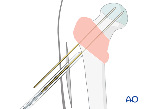
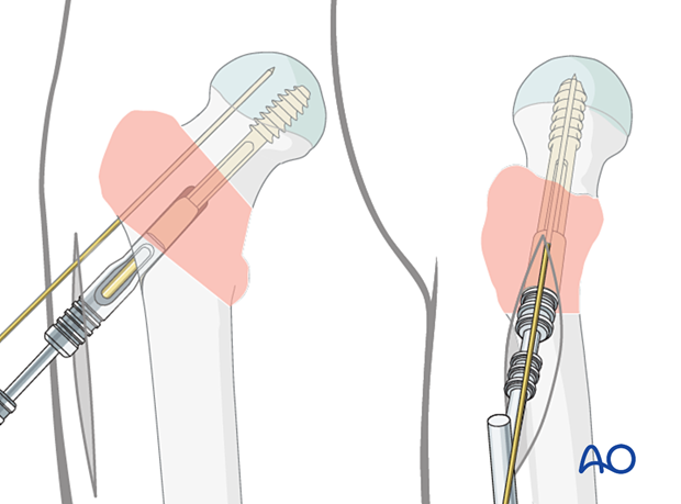
Determine the length of the lag screw with the help of the measuring device. Select a screw that is 5–7 mm shorter than the measured length.
Reaming
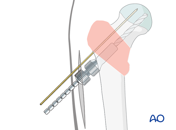
Adjust the cannulated triple reamer to the chosen length of the screw.
Slide the reamer over the guide wire and simultaneously drill for the lag screw, ream for the plate barrel, and countersink for the plate-barrel junction.
Insertion of the femoral neck screw
In patients with hard bone, it is best to tap for the screw. Otherwise, the screw may not advance, and you may displace the fracture by twisting the proximal fragment as you attempt to insert the screw.
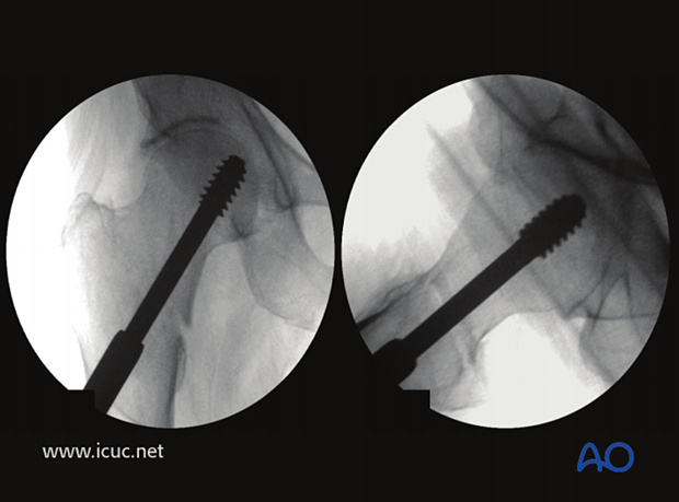
Mount the correct screw on the handle and insert it through the centering sleeve over the guide wire. By turning the handle, it is advanced into the bone. Do not push forcefully to avoid distraction of the fracture.
The antirotation wire may help to avoid rotational displacement.
When the screw has reached its final position – 5–7 mm short of the subchondral bone in the AP and lateral view – the T-handle of the insertion piece should be parallel to the axis of the proximal femur to ensure the correct position of the plate.
7. Fixation of the DHS plate
Application of the DHS plate
Take the plate with the previously chosen neck-shaft angle, slide it over the guide wire, and mate it correctly with the screw.
Push it in over the screw and seat it home with the impactor.
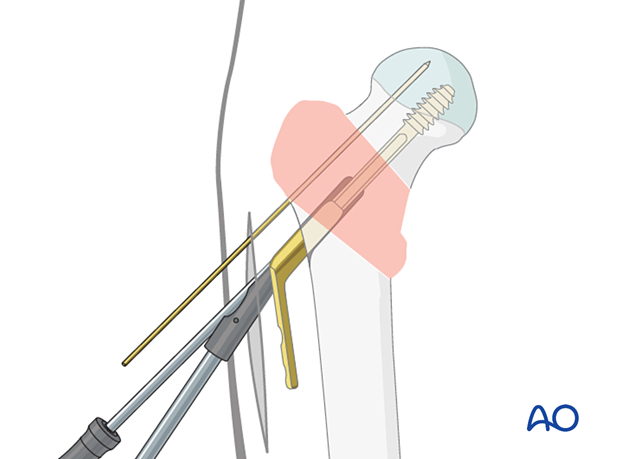
Plate fixation
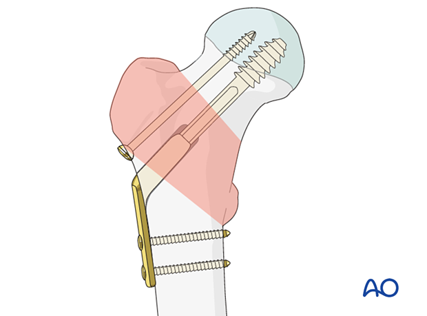
Fix the plate to the femoral shaft with an appropriate number and size of cortical screws.

8. Option: insertion of antirotation screw
If maintenance of rotational stability is required, insert a partially threaded cannulated screw over the antirotation wire parallel to the DHS lag screw.
9. Final assessment
Confirm fracture stabilization and implant position on AP, lateral, and axial views.
10. Aftercare
Postoperative mobilization
The elderly patient may start with weight bearing as tolerated with walking aids the day after surgery.
Unrestricted range-of-motion exercises of the hip joint are allowed.

Pain control
To facilitate rehabilitation and prevent delirium, it is important to control the postoperative pain properly, eg, with a specific nerve block.
VTE prophylaxis
Patients with lower extremity fractures requiring treatment require deep vein prophylaxis.
The type and duration depend on VTE risk stratification.
Follow-up
Follow-up assessment for wound healing, neurologic status, function, and patient education should occur within 10–14 days.
At 3–6 weeks, check the position of the fracture with appropriate x-rays.
Recheck 6 weeks later for progressive fracture union.
Implant removal
Only if necessary (eg, painful irritation), and not before union of the fracture. There is a high risk of a femoral neck fracture.
Prognosis of proximal femoral fractures in elderly patients
For prognosis in elderly patients, see the corresponding additional material.
11. Case
Preoperative AP image of the pelvis showing right intertrochanteric fracture

Initial AP and lateral images in the operating room with the patient in traction showing the fracture reduced
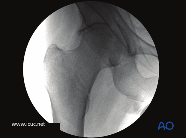
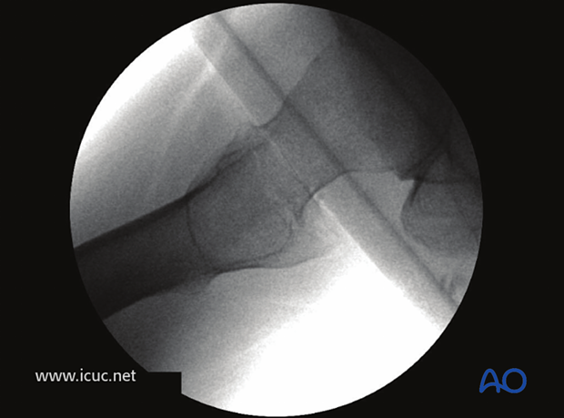
Axial image showing centrally positioned guide wire for DHS in line with femoral neck and shaft
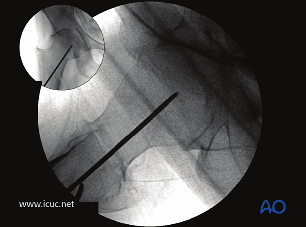
This image demonstrates insertion of the triple reamer.
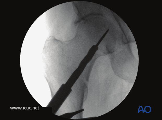
The hip screw is inserted under image intensifier control.
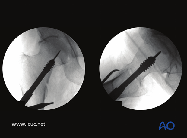
Postoperative image showing hip screw placed on both views with good tip apex position. (Tip apex distance in this instance is about 10 mm).
2 years postoperative image showing complete healing. It is recommended that two bicortical screws are placed in the DHS side plate.
