Femoral neck system
1. General considerations
The femoral neck system has advantages over DHS and cannulated screw fixation:
- No insertional torque resulting in less malrotation
- Compact design with a smaller incision, shorter operation time with fewer surgical steps, use in patients with narrow femoral neck
- Generally, higher resistance to varus collapse compared to fixation with three cannulated screws
- Implant collapse does not result in lateral protrusion and soft tissue irritation
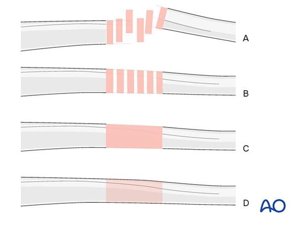
Throughout this treatment option illustrations of generic fracture patterns are shown, as four different types:
A) Unreduced fracture
B) Reduced fracture
C) Fracture reduced and fixed provisionally
D) Fracture fixed definitively
Closed vs open reduction
Fracture reduction should start with a closed attempt.
If manipulation does not lead to a satisfactory reduction, a percutaneous reduction technique should be performed.
The definitive decision for the treatment will be made after positioning the patient and an initial closed reduction. Since emergency department x-rays are often of suboptimal quality, verifying the preoperative diagnosis using image intensification is necessary.
Implant
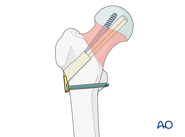
The femoral neck system consists of:
- Plate (one or two holes) with locking screw(s)
- Bolt
- Antirotation screw
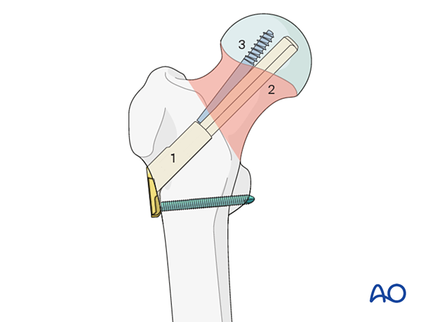
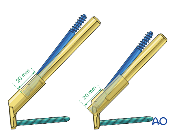
The antirotation screw is inserted through and locks to the bolt, the main load carrier.
They can slide together within the plate barrel up to 20 mm. The sliding allows for a controlled collapse of the fracture without lateral implant protrusion.
Implant size
As the bolt and antirotation screws are shorter than the overall implant length, the implant size is determined from the intraoperative measurement.
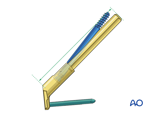
In small patients that would need an implant length less than 75 mm, the following technique should be used:
- Drill to the measured depth
- Select the shortest bolt and antirotation screw
- Do not fully insert the bolt; this will be adjusted with the insertion handle
The same technique may be applied with any implant length to limit the amount of collapse.
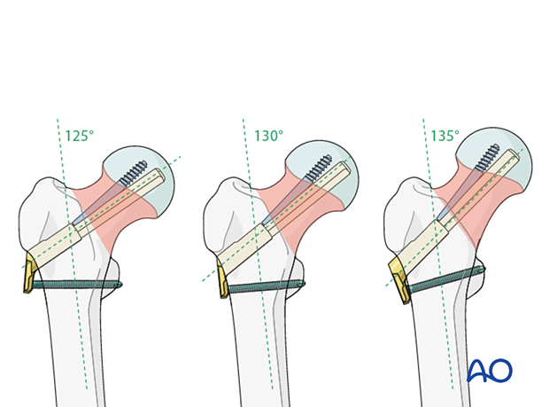
Neck-shaft angle
The central guide wire through the neck axis needs to be adjusted according to the patient’s anatomy and to reflect the neck-shaft angle (130°±5° possible).
The implant allows for this angular adjustment as the plate is very short.
AO teaching video
Femur, neck - Fracture 31B. Stabilization using the femoral neck system (FNS)
Karl Stoffel, Christian Kammerlander
2. Patient preparation
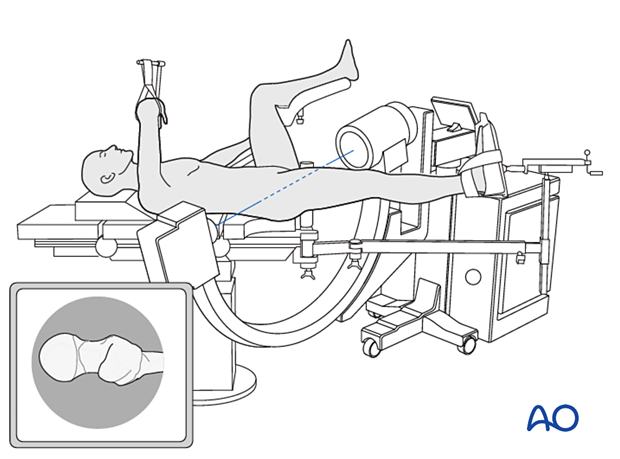
Position the patient supine on a fracture table. A conventional radiolucent table may also be used.
C-arm image intensifier control during surgery is a must.
It is easiest to obtain lateral and axial views to position the contralateral leg in a leg holder.
For C-arm positioning to acquire optimal AP, lateral, and axial views, read the additional material on:
3. Reduction
Closed reduction
Closed reduction is usually achieved by:
- Pulling in the direction of the long axis of the leg to distract the fragments and regain length
- Adjustment of internal rotation of the femoral shaft ...
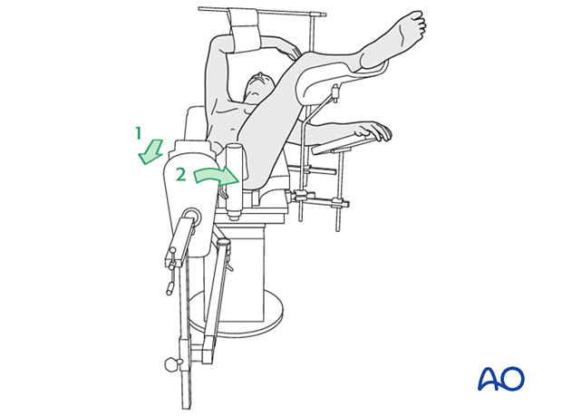
... until the patella is facing forward on an AP view of the knee joint
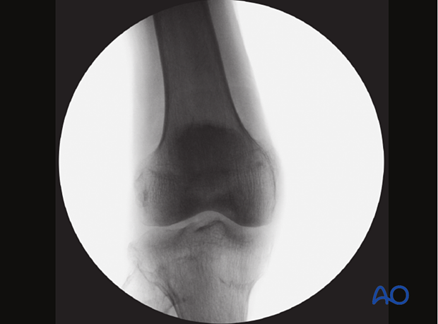
Check the reduction in both the AP and lateral view with an image intensifier.

Assessment of reduction quality
Read the fracture line on the image intensifier views. Identify gaps or increased density due to overlapping of fragments.
Follow the medial and lateral cortical lines on the AP view and the anterior and posterior cortical lines on the axial view. Identify any translational or angular malalignment.
Acceptable reduction quality shows the following patterns:
In the AP view:
- Continuous medial and lateral cortical lines
- No varus angulation
In the lateral view:
- Normal anteversion
- No retroversion
- Continuous anterior and posterior cortical lines
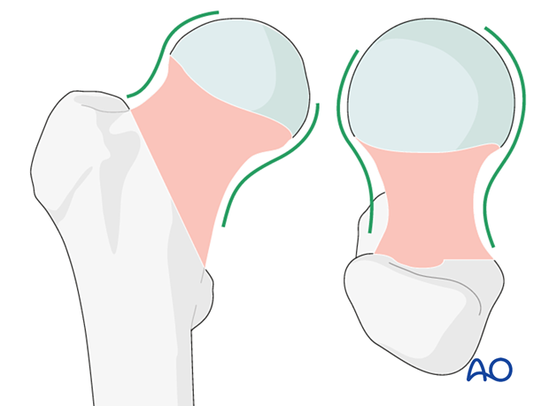
The cortical lines should show intact Lowell’s S-patterns (“lazy S”) in both views.
For more details, see the additional material on assessment of reduction quality.
Percutaneous reduction
If closed reduction is not satisfactory, carry out a percutaneous reduction technique.
Open reduction
If closed reduction fails, carry out an open reduction.
A two-window approach is most commonly used: reduction and preliminary fixation with reduction forceps through a Smith-Petersen approach and a separate lateral approach for implant insertion.
Alternatively, reduce and stabilize the fracture through an anterolateral (Watson-Jones) approach. Reduction maneuvers and visualization can be more difficult through this approach.
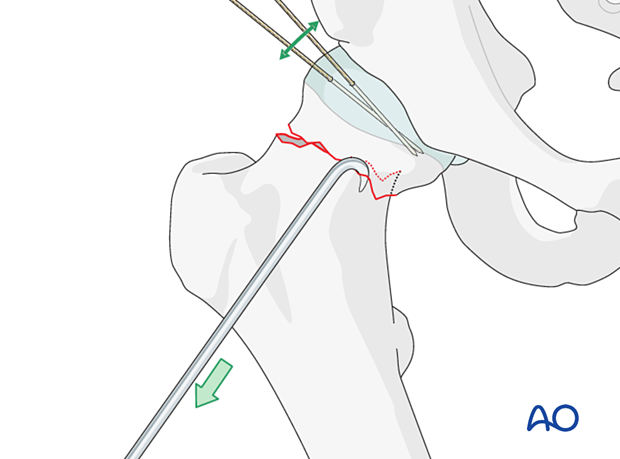
After the capsulotomy is performed, apply traction on the limb and manipulate the head and neck with hooks or K-wires, which can be inserted to act as joysticks until an anatomical reduction is achieved.
Confirm the reduction with the image intensifier.
Temporarily stabilize the fracture with K-wires.
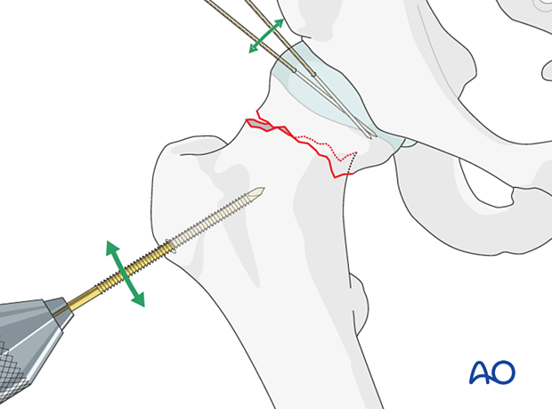
Alternatively, insert a Schanz screw through the lower part of the greater trochanter. This allows for traction and rotation of the distal fragment.
Insert two to three K-wires parallel to the head-neck axis for preliminary stabilization.
4. Approach for implant insertion
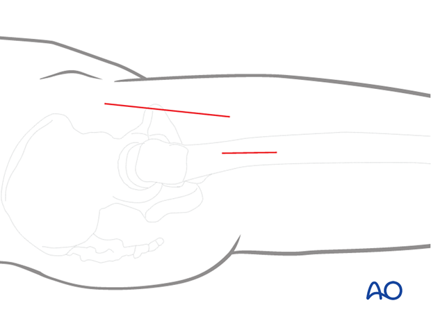
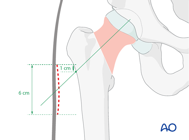
Perform a limited lateral approach to the entry site of the bone. Start its incision 1 cm proximal to the femoral neck axis crossing the lateral cortex, and enlarge it 6 cm distally. The approach should be large enough to insert the implant and locking screw.
In the true axial view, the incision should be directly lateral.
5. Guide-wire insertion
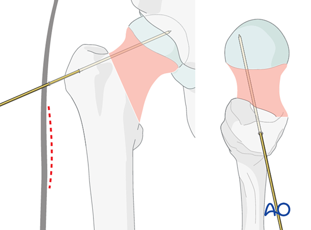
Insertion of antirotation wire
To prevent displacement during reaming and bolt and antirotation screw insertion, place a stabilizing wire across the fracture zone but away from the planned path of the implants.
Application of the aiming device
Seat the aiming device on the lateral cortex such that the screw trajectory runs through the head-neck axis or parallel and slightly inferior to that on an AP view.
Check its position with the image intensifier. In the axial view, the trajectory should be in line with the center of the head-neck axis.
Insertion of the guide wire
Insert the guide wire through the aiming device and advance it until the tip reaches the subchondral bone of the head. This helps prevent guide-wire pullout during reaming.
Position it so that, in the AP view, it runs through the center or slightly inferior to the neck. In the axial view, it should lie in the center of the neck.
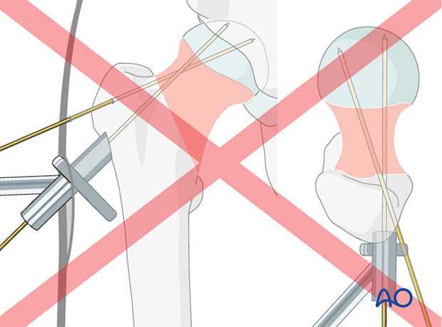
If the first attempt of guide-wire insertion ends up off-axis to the center of the femoral head, it is challenging to redirect the guide wire to the ideal position because the wire tends to fall back into the previous track.
Drill the wire in reverse mode, stripping the lateral cortex. Push it forward to redirect the wire to a subtle amount.
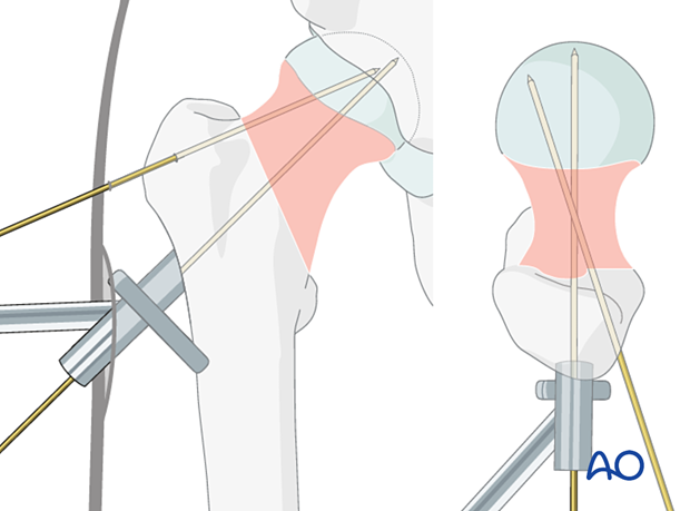
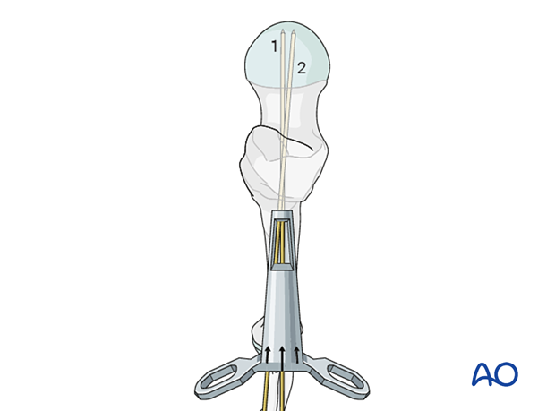
If the guide wire trajectory needs to be adjusted, use the dedicated correction guide. It allows one to introduce a new guide wire (2) parallel and/or at a slightly different angle to the first wire (1).
This illustration shows the insertion of the new guide wire through a new entry point slightly superior with an angular correction of 5°.
6. Implant insertion
Determination of the guide-wire length
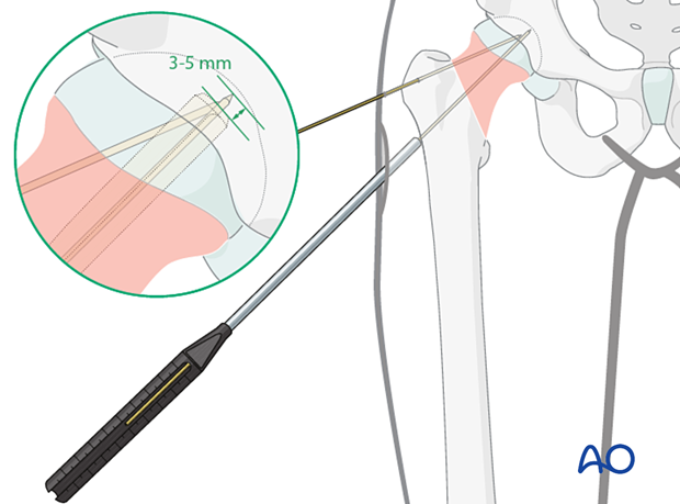
Determine the length of the guide wire with the measuring device. Select an implant size that is 3–5 mm shorter than the measured length.
Choose the longest possible implant to achieve the highest possible angular stability.
Reaming
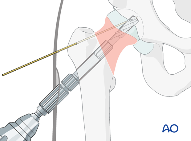
Adjust the reaming depth of the cannulated triple reamer to the selected implant length or, in small patients, to the measured wire length.
Slide the reamer over the guide wire and simultaneously drill for the bolt, ream for the plate barrel, and countersink for the plate-barrel junction. Confirm the reaming depth under image intensification.
Pearl: reinsertion of the guide wire

Assembling insertion handle and implant
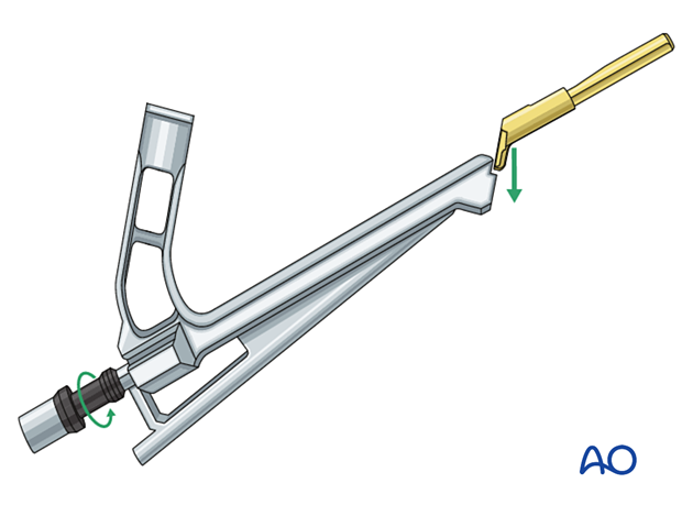
Assemble insert and insertion handle.
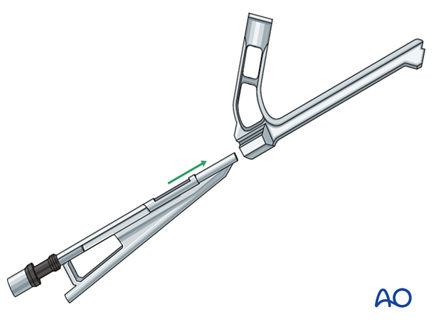
Insert the bolt of the chosen implant size into the plate barrel.
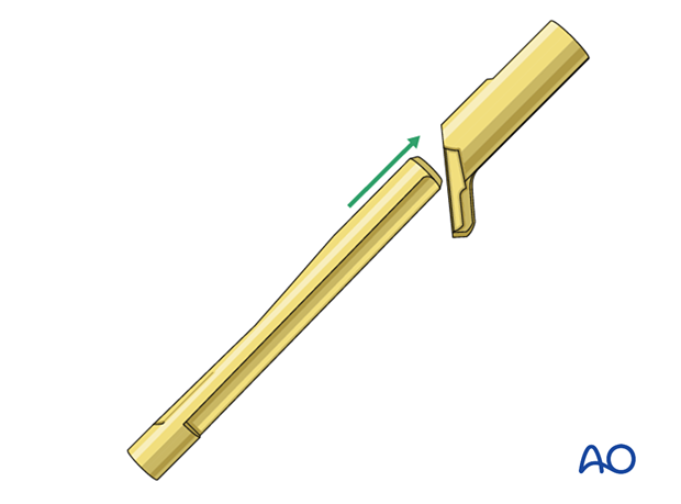
Attach the implant to the insertion handle and lock the attachment by tightening the black screw of the insert.
In small patients requiring an implant length less than 75 mm, eg, 70 mm, the black screw needs to be loosened by five counterclock half turns to shorten the construct by 5 mm (precollapse of the bolt).
Implant insertion
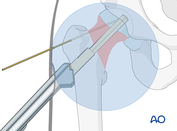
Slide the implant over the guide wire manually and push it until the plate is flush with the bone.
Slight taps with the dedicated cylinder or with a hammer onto the cylinder may help to achieve the final seating of the implant.

Rotate to align the plate along the femoral axis.
Check with image intensification if the implant is inserted correctly, ie, insertion depth, plate flush with bone, and in line with the femoral axis.
Remove the guide wire.
7. Insertion of screws
Sequence of screw insertion
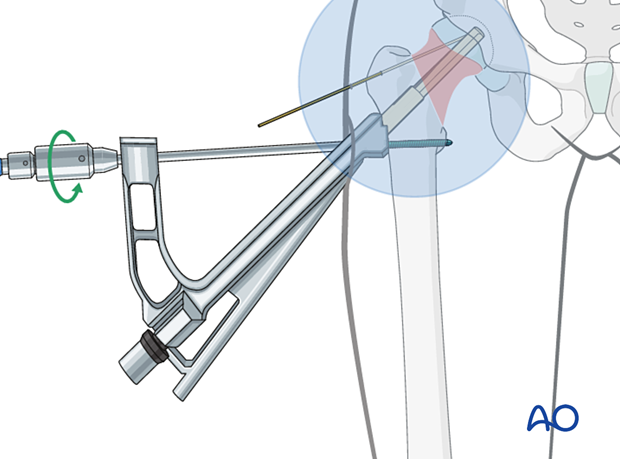
The locking screw through the plate is inserted first.

Plate fixation
Fix the plate to the femoral shaft with a bicortical 5.0 mm locking screw.
If a two-hole plate is used, insert the distal screw first.
Insertion of antirotation screw
Adjust the drill with a drill stop according to the implant size.
Drill the hole for the antirotation screw through the corresponding guide of the insert until the drill stop is flush with the insert.
In osteoporotic bone, there is often no need for predrilling.
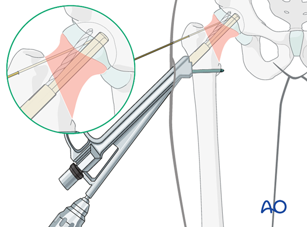
Insert the antirotation screw with a screwdriver.
Check the screw position on the image intensifier view before final tightening.
With the antirotation wire still in place, tighten the screw fully with a torque limiter.
Check with image intensification that the screw is fully inserted.
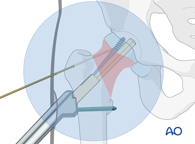
- The tip of the antirotation screw should be at the level of the tip of the bolt.
- The notch of the antirotation screw should be at the same level as the end of the barrel.
Remove the insertion handle and antirotation wire.

8. Option: intraoperative compression
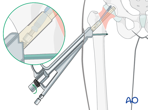
If indicated, the fracture may be compressed intraoperatively.
With the insertion handle still in place, manually insert the multifunction rod fully through the antirotation guide to lock antirotation screw and bolt.
Gently turn the black screw of the insert manually counterclockwise to apply compression. Monitor implant position and fracture compression with image intensification.
Remove the multifunction rod and insertion handle.
9. Final assessment
Obtain final x-rays in AP and axial views.
10. Aftercare
Postoperative mobilization
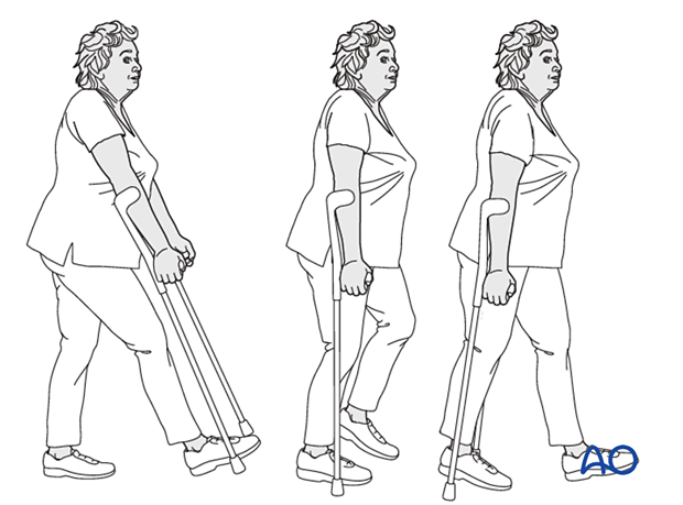
The elderly patient may start with weight bearing as tolerated with walking aids the day after surgery.
Initial restricted weight bearing is required for the young patient. This can be reassessed at 6 weeks.
Unrestricted range-of-motion exercises of the hip joint are allowed.
Pain control
To facilitate rehabilitation and prevent delirium, it is important to control the postoperative pain properly, eg, with a specific nerve block.
VTE prophylaxis
Patients with lower extremity fractures requiring treatment require deep vein prophylaxis.
The type and duration depend on VTE risk stratification.
Follow-up
Follow-up assessment for wound healing, neurologic status, function, and patient education should occur within 10–14 days.
At 3–6 weeks, check the position of the fracture with appropriate x-rays.
Recheck 6 weeks later for progressive fracture union.
Longer follow-up, at 6 months and 1 year, is indicated to assess the development of posttraumatic arthritis and/or avascular necrosis.
Implant removal
Only if necessary (eg, painful irritation), and not before union of the fracture. There is a high risk of a femoral neck fracture.
Prognosis of proximal femoral fractures in elderly patients
For prognosis in elderly patients, see the corresponding additional material.
11. Case
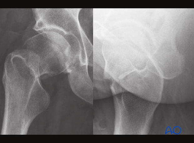
This 58-year-old patient is showing a multifragmentary transcervical fracture (AO/OTA 31B2, Garden 3, Pauwels 3).
Postoperative x-rays
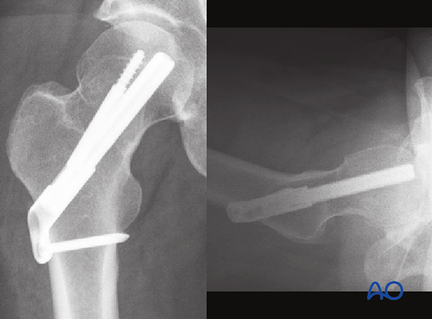
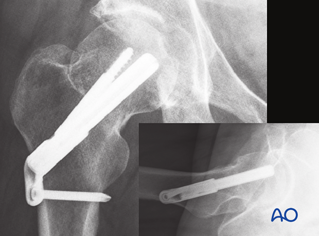
The 6-week postoperative x-rays show collapse of the fracture with sliding of the implant (arrow).
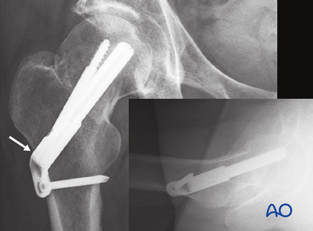
The 12-week x-rays show no further sliding.
