MIO - Bridge plating
1. Principles
Note on illustrations
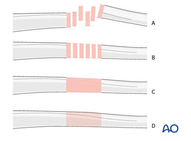
Throughout this treatment option illustrations of generic fracture patterns are shown, as four different types:
A) Unreduced fracture
B) Reduced fracture
C) Fracture reduced and fixed provisionally
D) Fracture fixed definitively
Bridge plating
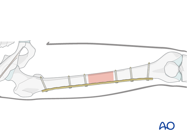
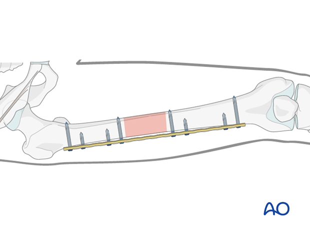
Bridge plating uses the plate as an extramedullary splint, fixed to the two main fragments, leaving the intermediate fracture zone untouched. Anatomical reduction of intermediate fragments is not necessary. Furthermore, their direct manipulation would risk disturbing their blood supply. If the soft tissue attachments to the fragments are preserved, and the fragments are relatively well aligned, healing is enhanced.
Alignment of the main shaft fragments can be achieved indirectly with the use of traction and the support of indirect reduction tools, or indirectly via the implant.
Mechanical stability, provided by the bridging plate, is adequate for gentle functional rehabilitation and result in satisfactory indirect healing (callus formation). Occasionally, a larger wedge fragment might be approximated to the main fragments with a lag screw.
Minimally invasive osteosynthesis
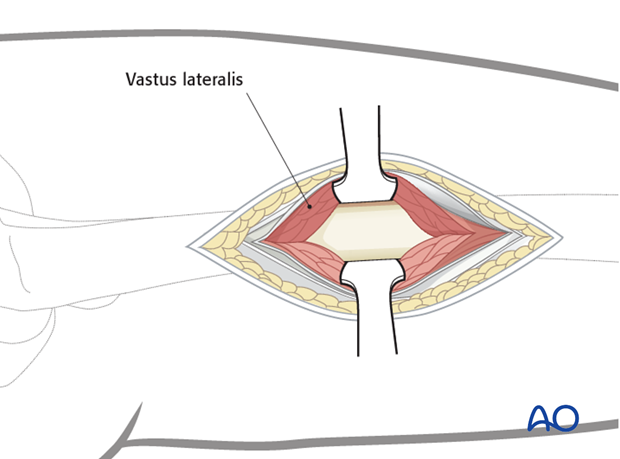
Bridge plates inserted through a minimally invasive (MIO) approach leave the soft tissues intact over the fracture site. The incisions are made proximally and distally, and the plate is inserted through a submuscular tunnel. This normally requires fluoroscopic intensifier monitoring.

Reduction
It is important to restore axial alignment, length, and rotation.
Reduction can be performed with a single reduction tool (eg, large distractor), or by combining several steps (for example fracture table +/- external fixator, cerclage wiring, +/- reduction via the implant, etc.) to achieve the final reduction.
The preferred method depends on the fracture and soft-tissue injury pattern, the chosen stabilization device, and the experience and skills of the surgeon.
If a large fragment has separated from the fracture zone and impaled the adjacent muscle, direct reduction may be required.
2. Preoperative planning
Plate type
Usually a broad large fragment plate is chosen.
A locking plate is a good option, especially in osteoporotic bone and for fractures with a short end segment. Such a locking plate does not need to be contoured precisely to fit the bone, since it functions as an internal fixator. Attaching it to the bone does not alter fracture alignment, since the screws do not pull the main bone fragments to the implant.

Regardless of the plate type used, the preferred dimension to stabilize femur midshaft fractures is a 4.5 broad dynamic compression plate (DCP) / limited contact - dynamic compression plate (LC-DCP) or a 4.5 broad locking compression plate (LCP) straight or curved.
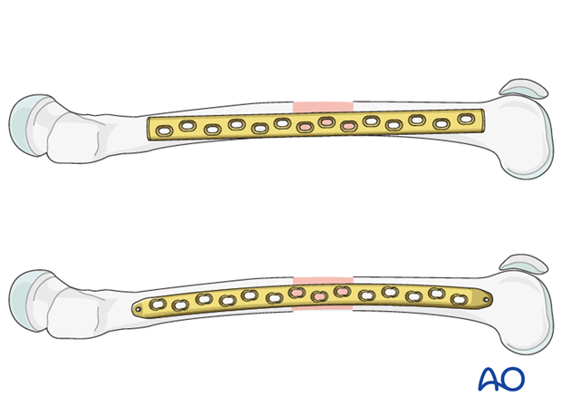
Plate length and number of screws
Generally speaking, the plates for the bridging technique should be longer than for conventional "anatomical" fixations, in order to distribute the forces more widely, as well as to provide relative stability.
Depending on the extent of the zone of fracture comminution and the underlying bone stock (osteoporosis), the appropriate plate length is chosen.
If the fracture location allows, the plate length should be chosen so that six plate holes are over each main fracture fragment.
Sufficient bicortical screws (a minimum of three up to six) should be inserted into each fracture fragment as necessary. The relative stability results from leaving plate holes empty over the fracture zone.
In total, no more than half of the screw holes need to be filled with screws. Remember, that no screws are inserted into the fracture zone.

3. Patient preparation
The patient may be placed in one of the following positions:
4. Approach
For this procedure a MIO approach is used.
5. Preliminary reduction
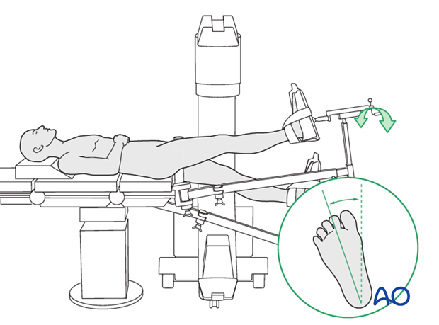
Reduction by using a traction table / manual traction
The use of a traction table can be beneficial.
Traction on the leg restores bone length, realigns the axis and restores tension in the soft tissues. Rotation must also be controlled carefully.
Interposed soft tissue may interfere with bone contact. If so, the interposed soft tissue may need to be cleared by exposing the fracture site directly.
Reduction by external fixator, or distractor
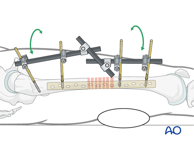
Especially with multifragmentary fractures, the use of an external fixator, or distractor, can provide alignment and temporary stability for bridge plating without disturbing the soft tissues at the fracture zone.
Proximal and distal pins should be inserted carefully in order not to interfere with the later plating procedure. For this purpose, the safe positions are anterolaterally, or anteriorly, on the femur.
If no traction table is used, folded linen bolsters under the fracture zone may facilitate reduction.
Teaching video
AO teaching video: Application of the large distractor
6. Contouring and insertion of the plate
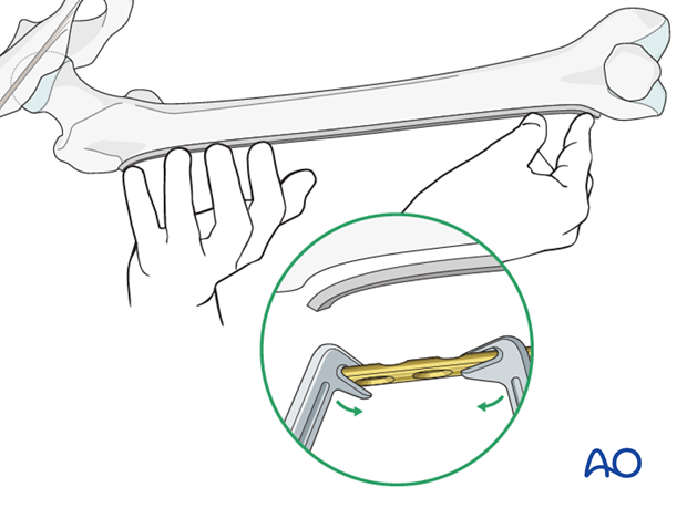
Contouring the plate
Contouring of the plate over the fracture site is normally not necessary. However, it is necessary to contour the ends of a conventional plate to address the anatomical shape of the proximal and distal femur.
A plastic femur bone can be used in a sterile bag as a template for the plate contouring maneuver.
A locking plate does not have to be contoured at all. However, to avoid soft-tissue irritations, slight contouring may be necessary.
In the minimally invasive technique, contouring is more demanding than in the open technique, requiring preoperative x-rays and planning, images of the fluoroscopic intensifier and a more experienced surgeon.
Direction of plate insertion
According to preoperative planning, the operative approach is chosen to insert the plate as well as some of the screws through the same incision. Further stab incisions / approaches may be necessary to insert the remaining screws.
Depending on the fracture location in the shaft area, it may be beneficial to insert the plate from distal, if the fracture is more distally located, or from proximal, if the fracture is located more proximally.

Preparation of the plate tunnel
Three options are in use for preparation of the plate path along the distal main fragment:
- Insert a long pair of scissors, spread them, and then pull backwards.
- Insert a periosteal elevator and slide it extraperiosteally along the distal main fragment. The tip of the plate can be used in a same manner.
- A soft-tissue retractor is available which serves the same purpose.
7. Reduction
Principle
When preliminary reduction is already optimal with respect to axis, length and rotation, the main fragments are held in this position using an external fixator, choosing the optimal screw positions in order not to conflict with the bridging technique.
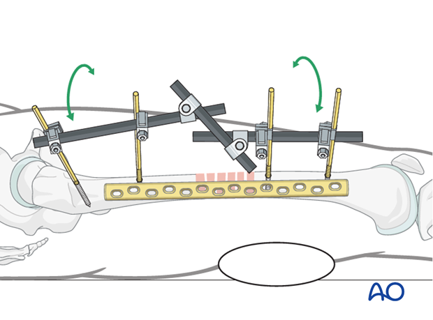
Most often, the preliminary reduction still needs some final adjustment for an optimal alignment. In such cases, the final reduction will be achieved using the implant and further multi-step reduction techniques. The following procedure describes one possible solution to achieve final reduction.
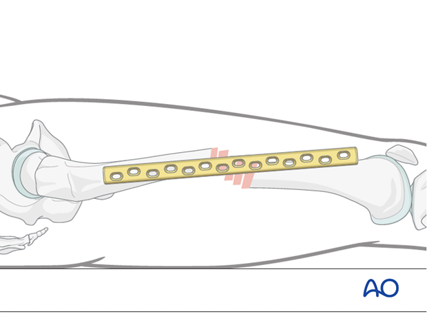
Image showing the AP view.

Lateral alignment and rotation
As an initial step, rotation and lateral alignment must be addressed.
8. Screw placement
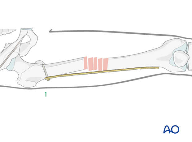
Positioning of first screw
The order of screw insertion depends on the direction of the plate insertion. In the following, we show the procedure for a plate inserted through a proximal approach.
The first cortical screw should be inserted through the approach used for the plate insertion, into the last plate hole. The plate should be positioned optimally in the lateral aspect.
Alternatively, when a LCP is used, a K-wire through a trocar can be chosen.
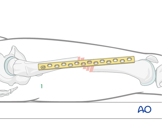
Image showing the AP view.
Positioning of second screw
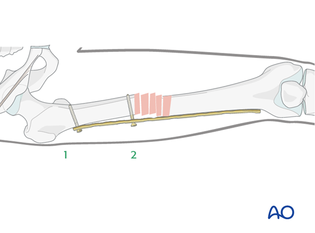
The second screw will assure that the plate is in the correct lateral position on the proximal fragment.
To achieve the correct alignment between the plate and the bone, a K-wire / Schanz screw can be used to push the proximal fragment into position. Alternatively, this can be achieved directly through a second approach, using a periosteal elevator to push the bone into position.
Then, the second cortical screw is inserted.
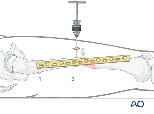
Image showing the AP view.
Assessment of rotation
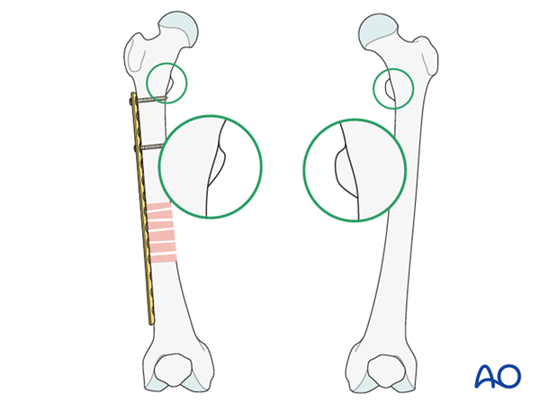
Prior to insertion of the third screw (first screw in the other main fragment), the rotation has to be checked again and the plate must be aligned to the distal lateral aspect of the distal fragment.
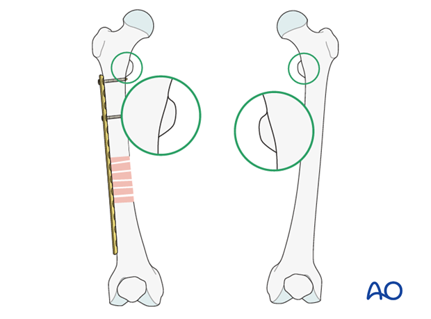
The shape of the lesser trochanter is compared with the contralateral side (lesser trochanter shape sign).
Correction of rotation
After the proximal plate fixation, the distal fragment is rotated with the patella facing anteriorly, as on the uninjured, contralateral side, by adjustment of the fracture table or by manual traction.
After the rotational relationship has been optimized, the lateral position of the plate must be checked.
A K-wire can be applied in the distal most hole to maintain the three-dimensional reduction.
Insertion of third screw
Insert the third screw through the most distal plate hole into the second main fragment.
One way to control the correct lateral position is to place a finger on the ventral aspect of the distal fragment and palpate the upper edge of the plate.
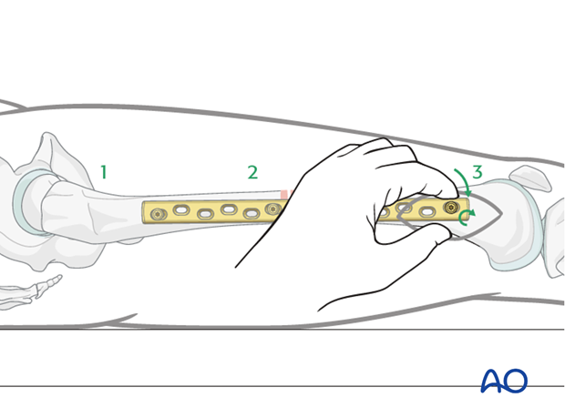
Image showing the AP view.
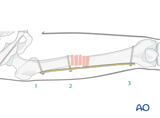
Insertion of fourth screw
If the distal fragment needs some final adjustment on the lateral aspect, the following reduction techniques may be helpful before inserting the fourth screw:
- placement of a linen bolster under the distal fragment;
- using a periosteal elevator inserted through the approach in order to push the fragment into the correct position; or
- using a percutaneous K-wire / Schanz screw.
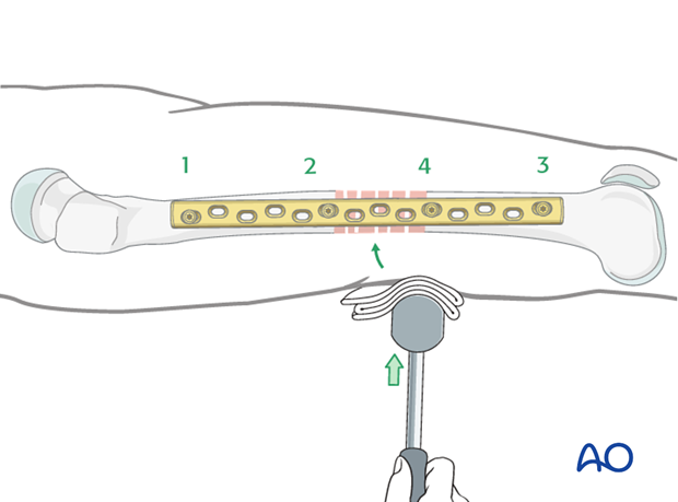
Image showing the AP view.
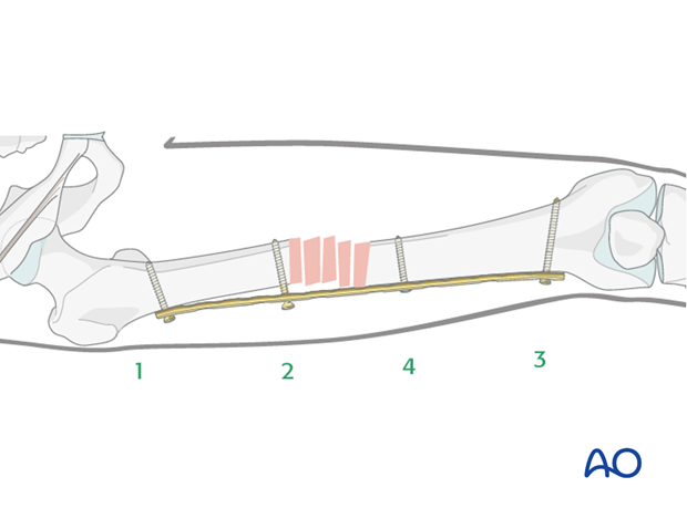
Alignment in the AP-view
By tightening the screws, the fragments are pulled towards the implant, and final reduction is achieved.

Final screw insertion
At the end, at least three bicortical screws must be inserted into each main fragment.

9. Internal fixator - locking plate system
Preliminary fixation
An internal fixator has the advantage that an optimal reduction can be achieved even if the plate is not correctly precontoured.
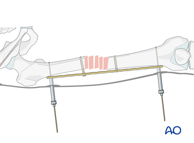
Reduction
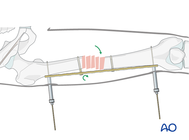
By tightening the two conventional screws, reduction is achieved (even with a gap between the bone and the implant).
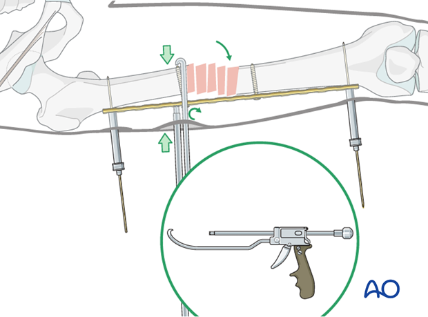
Alternative: In cases where reduction is difficult a Verbrugge or collinear clamp (illustrated) can be used via a small incision.
Final screw fixation
The final reduction is then fixed by inserting locking head screws according to the preoperative plan after removal of the temporary conventional reduction screws.
10. Aftercare
Compartment syndrome and nerve injury
Close monitoring of the femoral muscle compartments should be carried out especially during the first 48 hours, in order to rule out compartment syndrome.
Postoperative assessment
In all cases in which radiological control has not been used during the procedure, a check x-ray to determine the correct placement of the implant and fracture reduction should be taken within 24 hours.
Functional treatment
Unless there are other injuries or complications, mobilization may be started on postoperative day 1. Static quadriceps exercises with passive range of motion of the knee should be encouraged. If a continuous passive motion device is used, this must be discontinued at regular intervals for the essential static muscle exercises. Afterwards special emphasis should be placed on active knee and hip movement.
Weight bearing
Full weight bearing may be performed with crutches or a walker.
Follow-up
Wound healing should be assessed regularly within the first two weeks. Subsequently a 6 and 12 week clinical and radiological follow-up is usually made. A longer period may be required if the fracture healing is delayed.
Implant removal
Implant removal is not mandatory and should be discussed with the patient, if there are implant-related symptoms after consolidated fracture healing.
11. Case
Preoperative AP image of a midshaft fragmentary wedge fracture in a 20-year-old polytrauma patient. External fixation was applied for damage control.
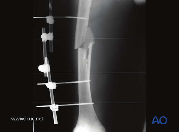
As the patient is now stable for definitive fixation of the femoral shaft, the external fixation is being removed.
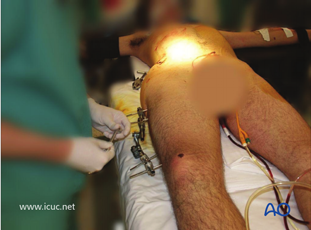
An LCDCP is inserted distally prior to fracture reduction.
Note that the external fixation pin sites have been cleaned before plate insertion.
External fixation of the pelvis is still in place for another injury.
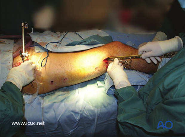
Initial distal plate placement.
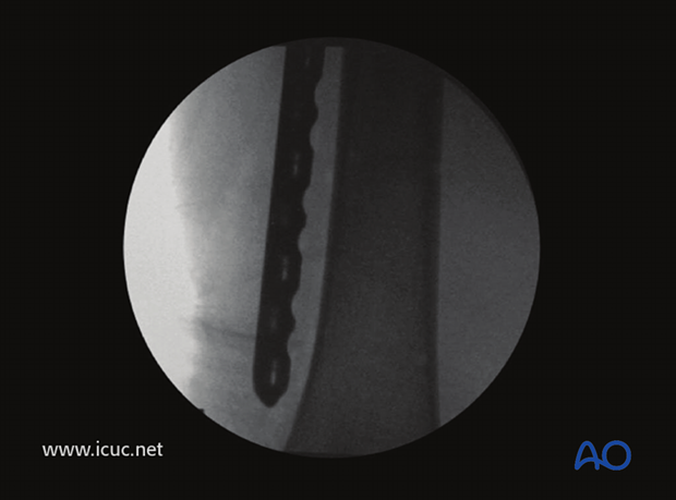
Plate in place before reduction and screw fixation.
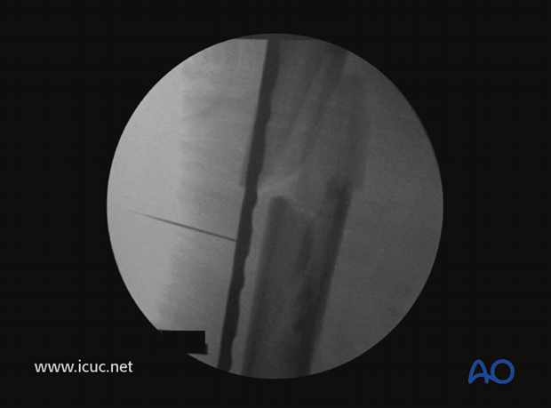
Reduction is fine-tuned using MIS technique.
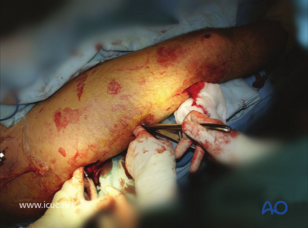
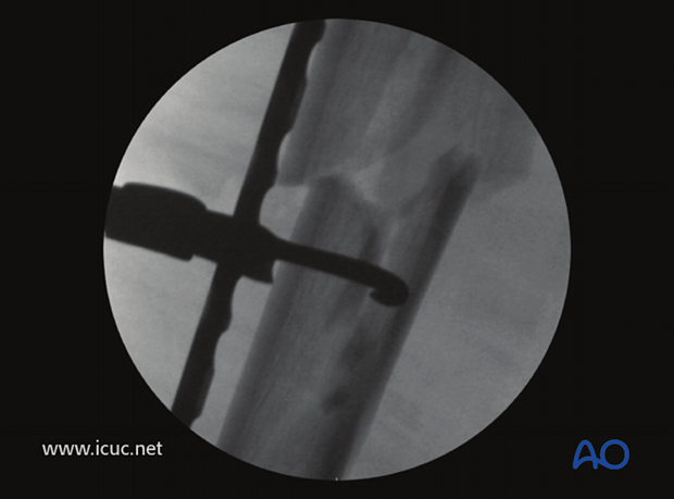
A colinear clamp is used to assist with fracture reduction.
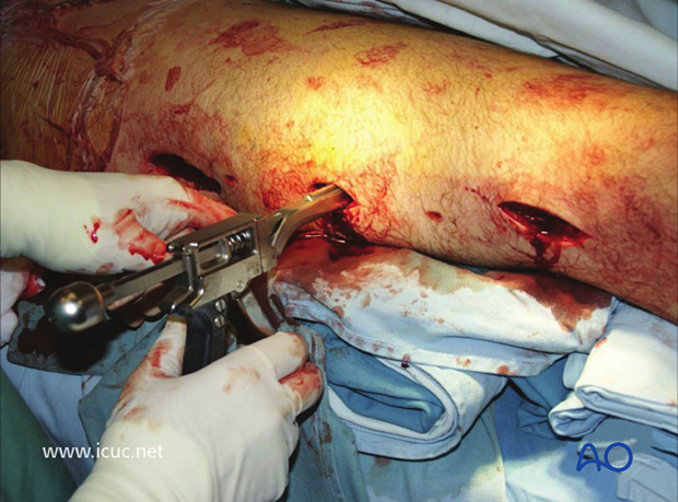
Fluoroscopic imaging is used to guide reduction before plate fixation with locking head screws. The plate was applied in bridging mode to allow for bone healing through callus formation.
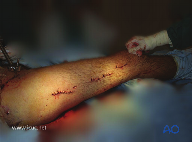
Final closure.
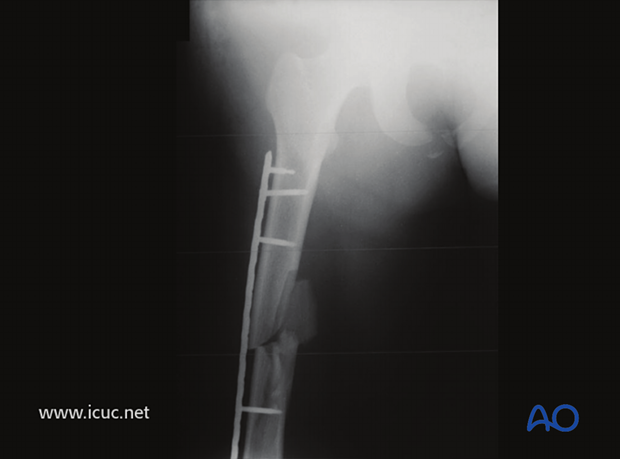
Postoperative AP image of the plated femur.
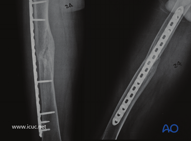
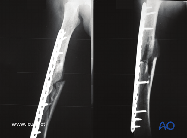
6 weeks postoperative AP and lateral images.
14 weeks postoperative AP and lateral image showing exuberant callus evident.
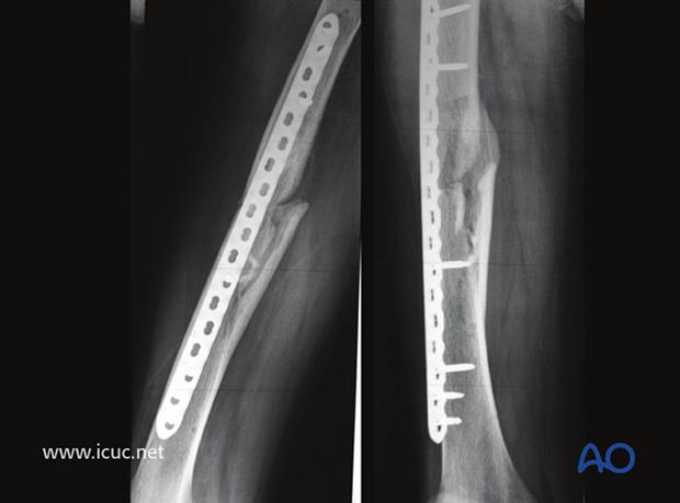
2 years postoperative AP and lateral images showing complete fracture healing with callus.
