Temporary external fixator
1. Principles
General considerations
Temporary versus definitive treatmentTheoretically, the mandibular external fixator could be used to achieve definitive bone healing. Nevertheless, the external fixator does not offer the same degree of stability compared to internal devices.
The external fixator device will often only be applied temporarily, with subsequent replacement by an internal fixation system.
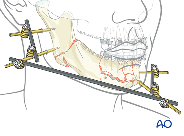
The external pin fixation device gives a high degree of freedom for the frame assembly as the pins can be placed selectively into each segment and connected with short bars to constitute a subunit. Subsequently, the subunits are joined with additional connecting elements to make up the complete framework. In this process, each subunit can be manipulated into a reduced position until final tightening of the whole construct.
This 3D model shows an external fixator that consists of two partial frames (one on each fracture fragment), joined by a rod-to-rod connecting rod. In this model compressive stress is shown in red and tensile stress is shown in blue.
Attaching an additional rod (neutralization rod) to the two partial frames increases the stiffness and stability of the modular external fixation frame. In particular, doing this adds rotational stability and increases the bending strength, thereby significantly reducing strains at the connecting rod. The surgeon can decide during the surgery if the neutralization rod is needed for additional stability or not. The rod may be attached at each end to either a pin (as shown here) or a rod.
A neutralization rod is shown in the lower model.
Some disadvantages of an external fixator are:
- The extensive amount of hardware necessary for this complex construct
- The quality of the bony reduction is not guaranteed as the reduction is often not visualized (closed reduction)
Alternative: biphasic pin fixation
An alternative to the modular technique is biphasic pin fixation (also known as the Joe Hall Morris fixation).
Fracture alignment is first achieved with adjustable connecting rods between the pin pairs (not shown in the illustration).
The aligned pins are then covered with a silicon tube (eg, endotracheal tube, chest tube) and then injected with methyl methacrylate resin.
Alternatively, the pins can be connected with a molded methyl methacrylate block that sets after application.
Finally, after adequate bone healing, the pin fixation and adjustable rods are removed.
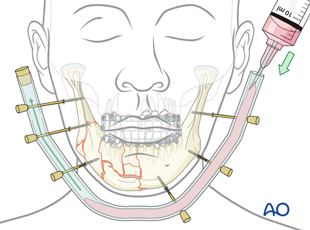
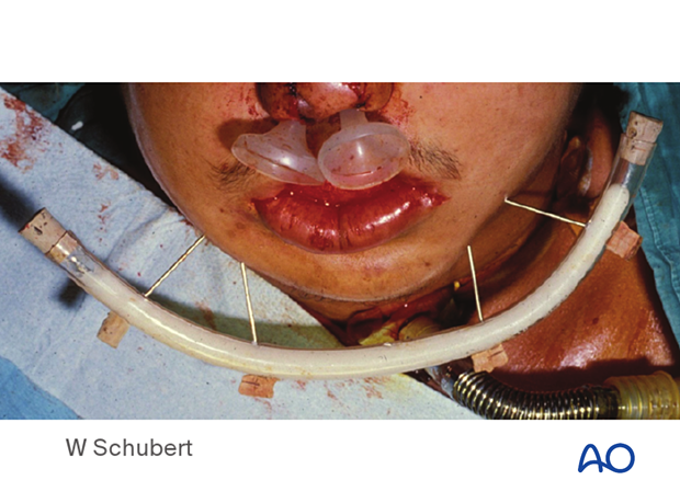
This image shows an example of this technique following a self-inflicted gunshot wound, where a plating system or modern fixator was not available.
In this case, the fixation is nonrigid and can lead to instability of the framework. However, it is readily available and may be considered when nothing else is available. Larger threaded Steinmann-type pins would be preferable over K-wires.
Biomechanical considerations
The following recommendations apply to optimize the framework stability:
- Choose large pin diameters (Schanz screws or Steinmann pins may be considered)
- Use at least two pins in each fragment
- Keep a large distance between the pin pairs
- When possible, place pins at least 1 cm from the fracture line
- Place the connecting rods or plastic bar close to the skin surface to keep the lever arms short.
2. Patient preparation
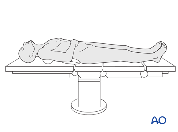
This procedure is typically performed with the patient placed in a supine position.
3. MMF
If the major fragments can be aligned using any of the MMF techniques, MMF is used to simplify the overall assembly process.
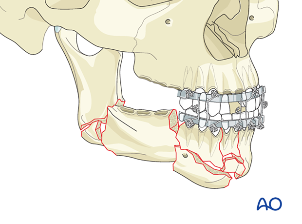
4. Pin insertion
Pin locations
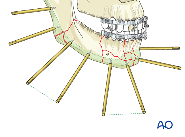
The pins are inserted through the soft-tissue envelope overlying the safe zones into the mandible's lower border.
For more information on the anatomy of the mandible, click here.
Two pins are inserted into each major fragment at an appropriate distance from each other and the adjacent fracture lines.
The length of the threaded portion of the pins is chosen to attain bicortical engagement.
Stab incision
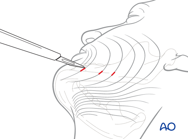
A small stab incision is made to prepare for pin insertion at the predetermined screw location in the posterior mandible.
The stab incision is done with the blade parallel to the RSTL (relaxed skin tension lines).
Soft-tissue dissection and protection
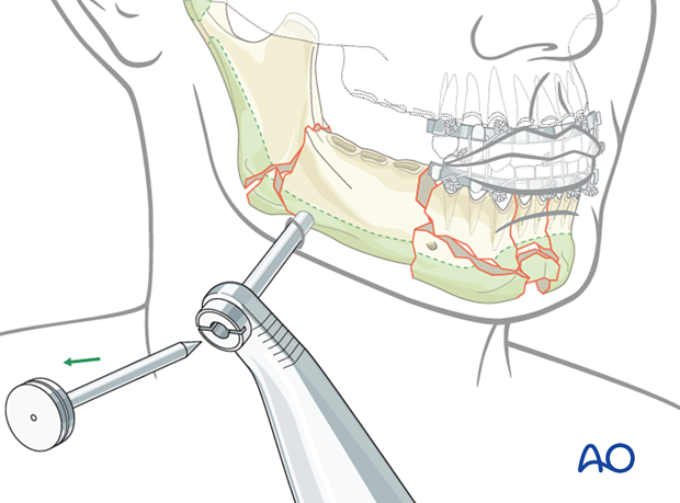
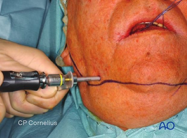
Bluntly dissect a soft-tissue channel onto the underlying bone and insert a trocar for soft-tissue protection through the channel until it contacts the bone.
Pin insertion
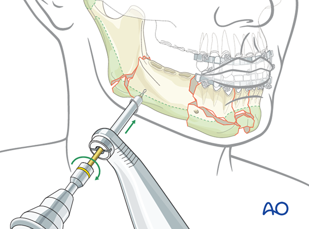
A self-drilling pin is loaded into a handle. Use the trocar as a guide and drive the pin into the bone down to the pin's base.
If a self-drilling pin is not available or not advisable due to fragment instability, make sure to pre-drill before pin insertion.
The clinical photograph shows pin insertion with a trocar.
5. Frame assembly
Creation of subunits
The two pins in each fragment are connected with a rod and two clamps (as illustrated). The example here shows four subunits.
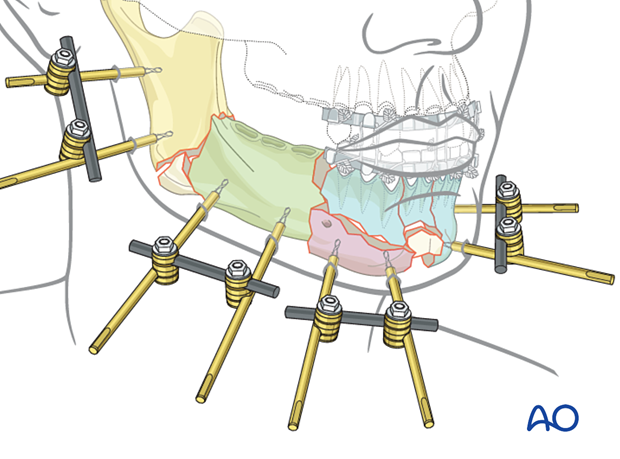
Linking the two posterior subunits
Apply a connecting rod loosely between two subunits using rod-to-rod clamps.
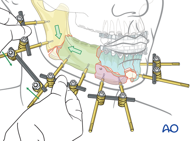
Once the fracture is manually reduced by manipulating two subunits, tighten the rod-to-rod clamps.
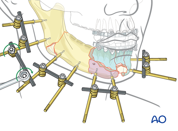
Linking the anterior subunits
The anterior subunits are linked in the same way as the posterior subunits.
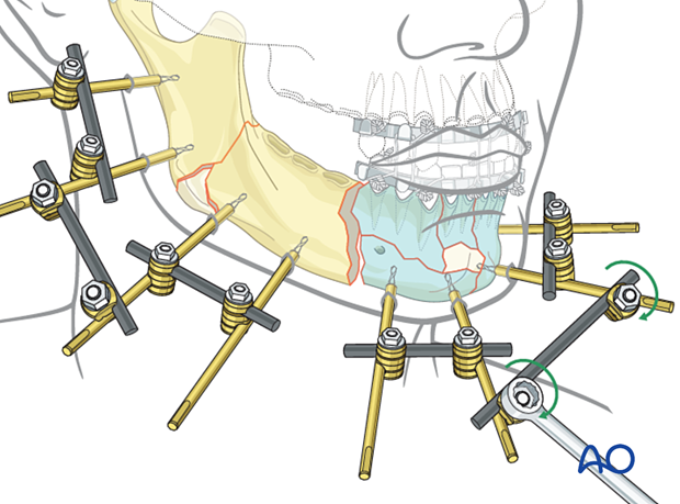
Final frame assembly
Only one fracture gap is left between the two large assembled mandibular portions. To connect the anterior and posterior subunits this gap is reduced and fixed with a connecting rod.
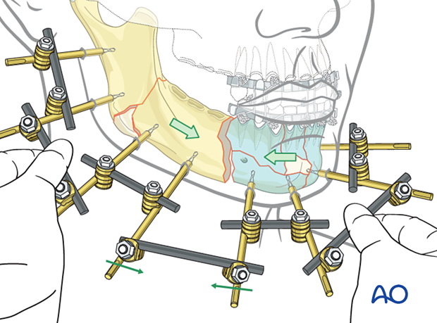
The illustration shows the final assembly of the external fixator using the modular technique.

MMF is removed after the final assembly of the external fixator to allow for mandibular function.
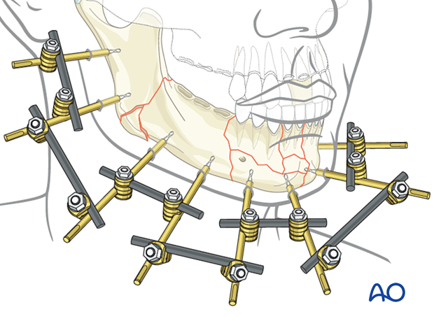
Alternative: using a bow
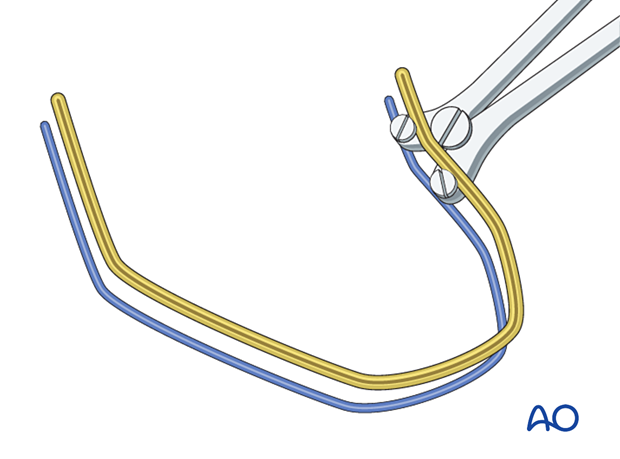
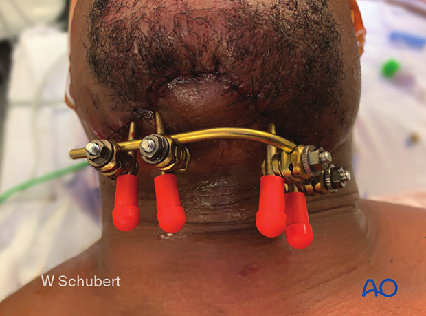
When a large circumference of the mandible requires external fixation, a pre-contoured rod can be directly attached to the pins.
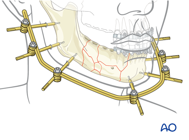
A template rod is first inserted into the combination clamps.
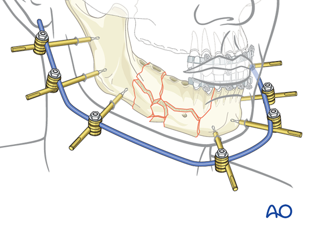
This template rod is then used to make further adjustments during the bending of the bow-shaped rod.
This clinical picture shows an alternative placement of the bow on the inferior border. The patient had a history of comminution, multiple infections, and a parasymphyseal defect. Multiple attempts at treatment using ORIF and traditional plating techniques had failed.
The postoperative orthopantomogram shows Schanz screws. Note that the screw on the far left is too close to the inferior alveolar nerve.

6. Aftercare following external fixation
General
External fixation of the mandible is usually temporary. Conversion to, and the timing of conversion to internal plate fixation is at the discretion of the surgeon. The patient’s general condition and the local soft tissues must be suitable to allow this conversion.
The patient should be taught appropriate pin care. Soft tissues around external fixation pins are treated with pin-site cleansing, antibacterial ointments, and dressings.
Intraoral wounds
In the presence of intraoral wounds, appropriate guidelines for mouth rinses and diet must be followed. Regular appointments at short intervals are mandatory.


