Bimaxillary correction
1. Introduction
In one-jaw surgery the position of the non-osteotomized jaw will dictate the final position of the jaw that is being moved. In this case computer assisted planning will normally not be performed.
However, in bimaxillary surgery the position of both jaws can be changed in all three dimensions. In these cases computer assisted planning has proven to be a valid alternative to dental model surgery.
As all bony structures can be evaluated in computer assisted planning. It is an invaluable tool when dealing with facial asymmetries involving the ramus and condyle. Furthermore, since soft tissues can be included in the virtual model, midline adjustments can be performed more accurately than with the use of plaster casts.
However, reproduction of the virtual planning in the operating room will require a digital workflow including CAD-Cam, splint fabrication or patient specific plates and cutting guides.
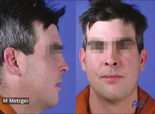
We will demonstrate the virtual planning of an asymmetric bi-maxillary case presenting with maxillary retrusion and mandibular protrusion.
Note: the patient has deviation of the upper jaw to the right, the lower jaw to the left, and chin to the left relative to the facial midline.
Useful additional reading
2. Data acquisition
CT/CBCT acquisition
For the virtual planning a CT scan and/or cone beam CT data is imported into the planning software. Slice thickness less than 1.0 mm is recommended.
The pros and cons of fan beam versus cone beam is discussed here.
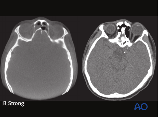
The CT scan data may be used for soft tissue simulations.
Scan of the dentition
CT scans produce artifacts around the teeth due to dental restorations and orthodontic appliances. Therefore, a high resolution scan of the teeth is not possible from the CT scan.
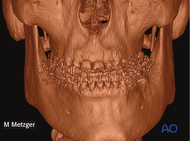
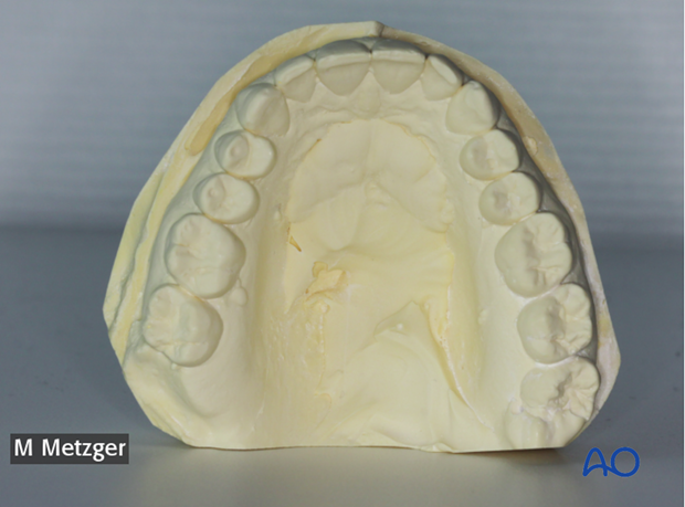
A surface scan of the dentition can either be made from plaster models using a CT scanner, optical scanner.
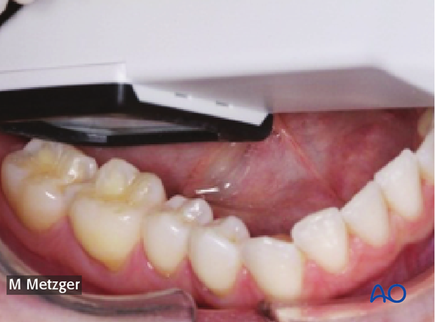
Alternatively, the dental arch can be scanned using an intraoral scanner.
Note: Scans of the dentition should not be more than one month old due to potential tooth movement.
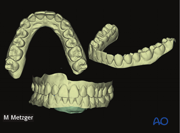
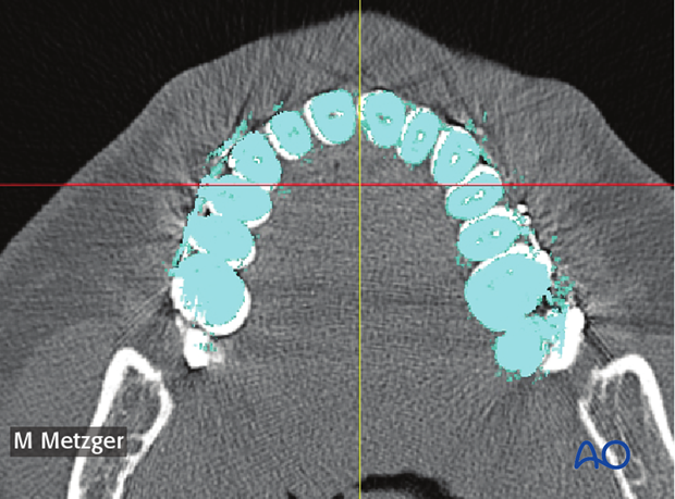
The scans are made of the maxilla and mandible separately as well as in occlusion. Examples of the virtual tooth surface obtained from the scan can be seen on the left.
Note: The scan of the dentition in final occlusion is made either by repositioning the dental arches virtually or scanning the plaster casts in final occlusion (with or without segmental surgery).
Face scan
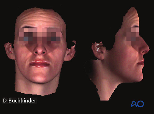
A face scan is obtained when soft tissue simulation is required. In addition, when explaining the operative procedure to the patient, the overlay of a "natural looking" face may give a more realistic impression due to the natural texture.
3. Data processing
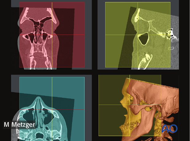
Skull position alignment
The patients' virtual skull must be oriented in space to approximate natural head position.
To find the mid sagittal plane, it is important to align the coordinate planes. The alignment can be performed in the following way.
To start the alignment, the center point of the coordination system is placed at nasion.
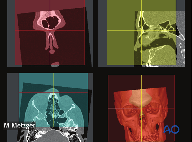
Using the bi-pupillary line and the skull base as a reference, a transverse alignment is made.
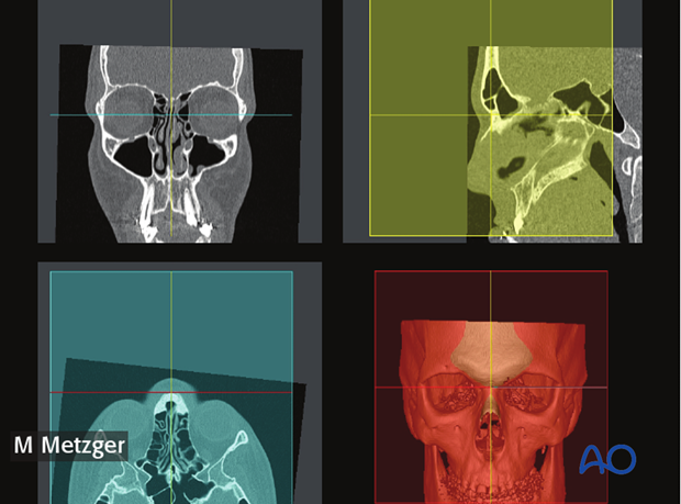
The coronal adjustment is performed using the lateral aspects of the orbital rim as reference points.
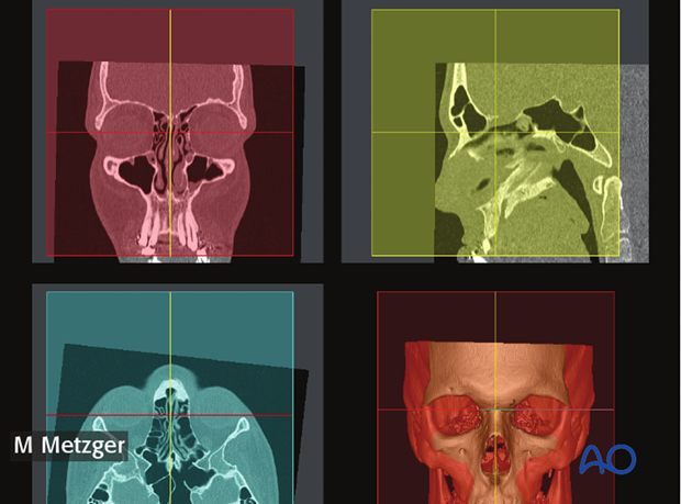
Finally the sagittal adjustment is made by using the Frankfurt horizontal plane bilaterally.
Cephalometric analysis
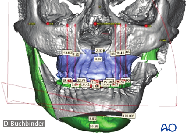
Cephalometric analysis is performed in order to:
- Quantify the desired anterior/posterior and vertical movements.
- Allow a comparison between pre- and postoperative as well as the virtual and actual results.
Data fusion
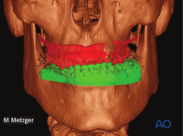
The scans of the surfaces of the dentition can be fused into the CT dataset at this point or at a later stage, prior to preparing occlusal splints.
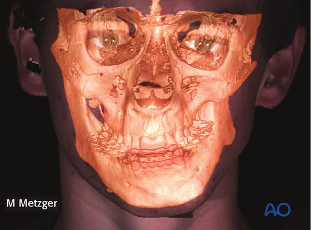
Additional data from the facial soft tissue surface scan could be fused into the data set. (This picture showing a different case).
Segmentation
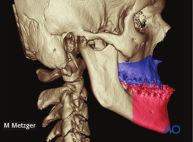
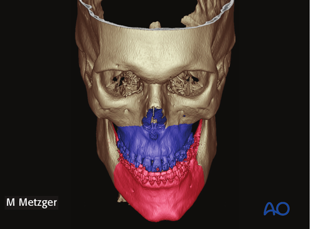
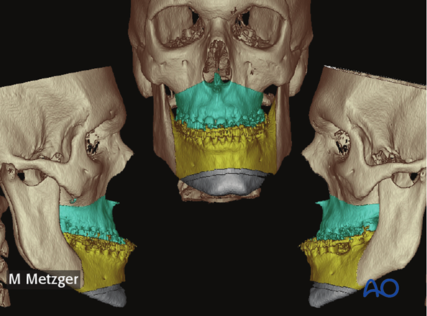
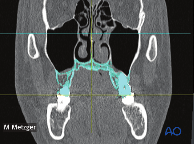
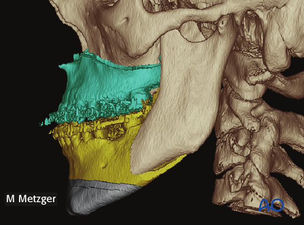
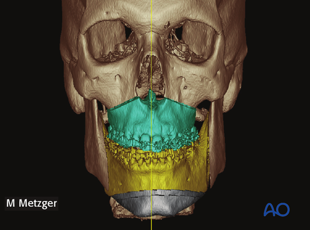
The segmentation is performed using the planned osteotomy lines. In this case a Le Fort I osteotomy, bilateral sagittal split osteotomies (BSSO), and a vertical reduction genioplasty are planned.
4. Virtual maxillary correction
Virtual repositioning
The occlusal cant is determined by tracing a line between the maxillary molars (yellow line) and comparing it to the horizontal reference line (blue)
Note: This case there is not an occlusal cant.
In the axial view, the midline symmetry is evaluated. In this case a clockwise rotation around the midpoint of the maxillary segment was necessary.
The necessary anteroposterior movement is evaluated in the sagittal view. In this case an anterior movement of 5 mm is performed as determined by the cephalometric analysis and clinical evaluation.

Preparation of intermediate occlusal splint
To allow for the preparation of the intermediate occlusal splint, the mandible is rotated open using the intercondylar axis.
The mandible is rotated until no further occlusal interferences are noted.
The picture on the left show the planned maxillary position (red) interfering with teeth of the mandible (green).
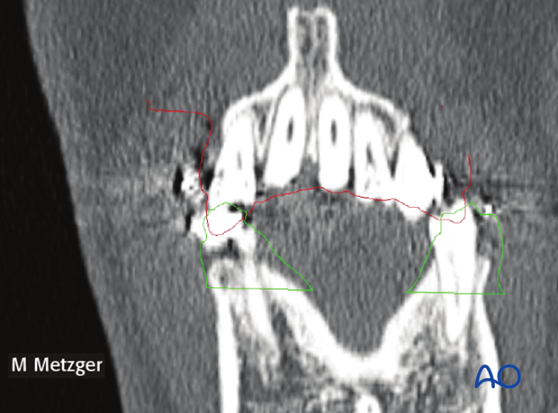
A virtual intermediate splint can now be designed to relate the operated maxilla to the non-operated mandible.
The intermediate splint is then produced using a 3D-printer.
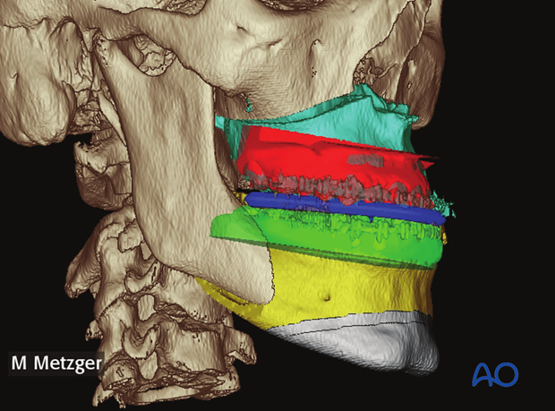
5. Virtual mandibular correction
Virtual repositioning
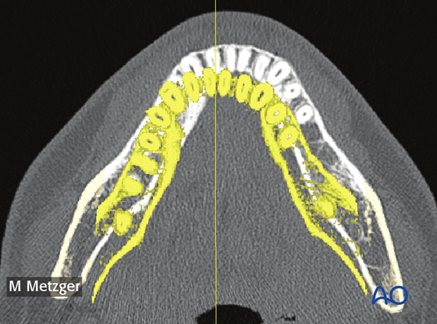
The data from the surface scan with teeth in the final occlusion is now imported and overlaid to the final position of the maxilla, establishing the position of the distal segment of the mandible.
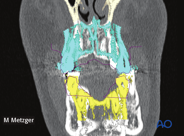
The virtual planning shows interference between the repositioned distal mandibular segment and the proximal segment (due to rotation of the distal segment). Additional bone removal may be necessary in the area of the interferences.
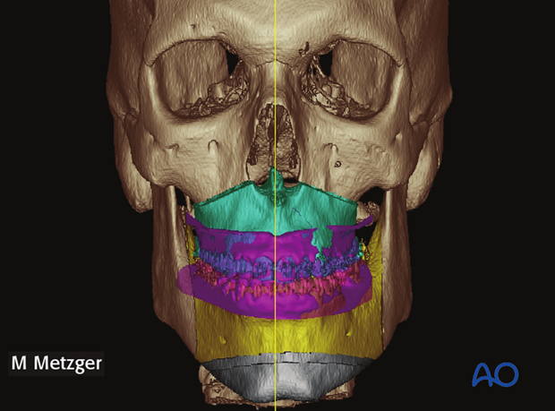
Preparation of final occlusal splint
A virtual intermediate splint can now be designed to establish the final occlusal position (operated mandible).
The final splint is then produced using a 3D-printer.
6. Virtual chin correction
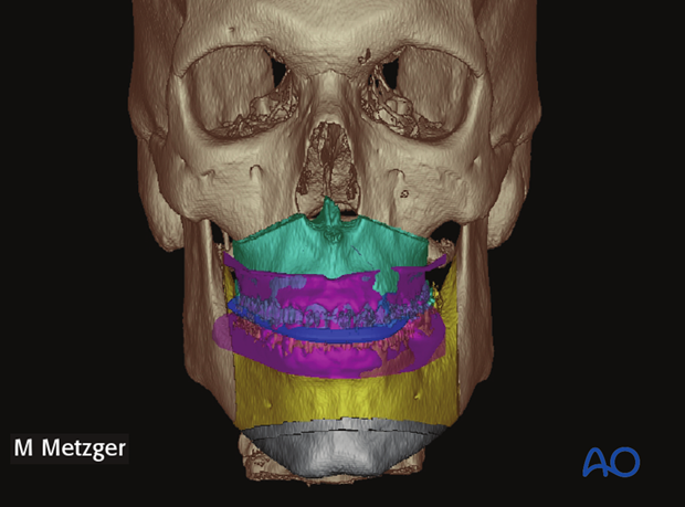
In this case a vertical chin reduction and an asymmetry correction is planned.
7. Clinical pictures
Preoperative frontal and profile picture.
Preoperative occlusion.
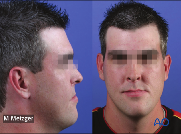
Postoperative frontal and profile picture.
