Instrumentation for occipitocervical fixation
1. Introduction
Occipital plate
There are several plate systems available for the occiput. Their application is based on the same principles, and to illustrate these concepts, we will show the use of a plate placed in the midline, which allows for modularity and rotation when connecting to the rods.
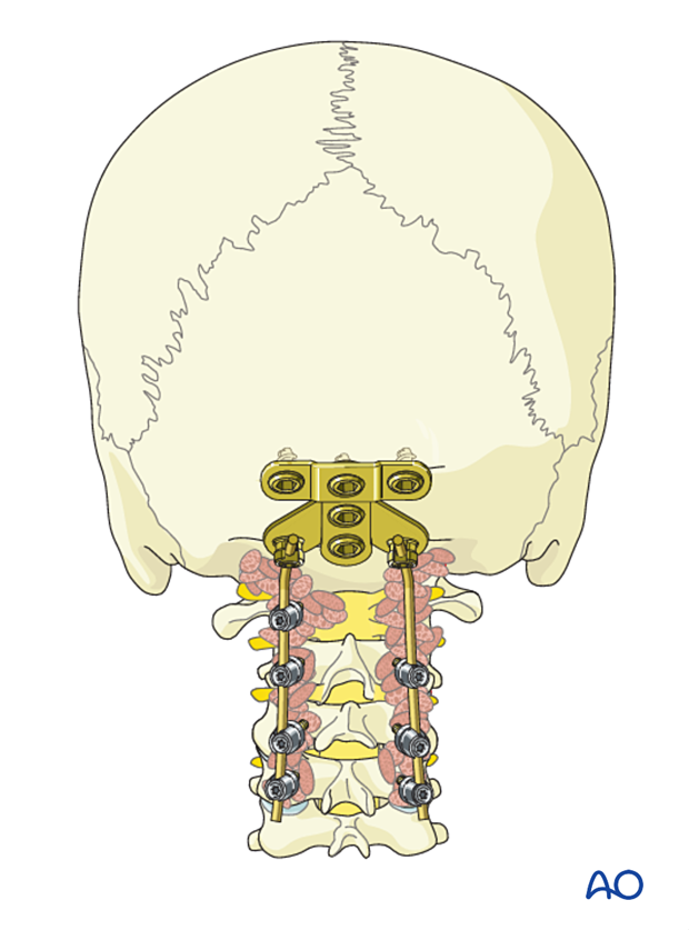
Plate placement
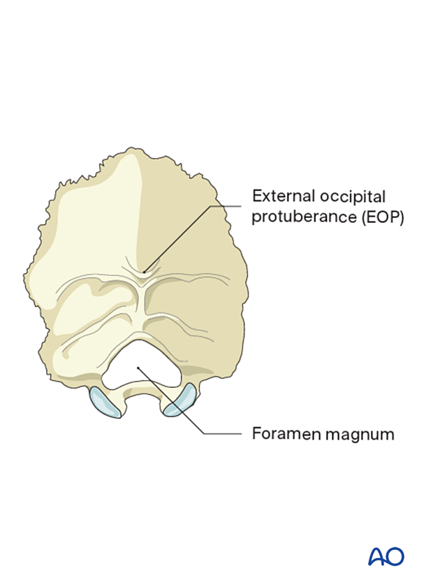
Independently of the plate system used, its placement should be close to but still caudal to the external occipital protuberance (EOP).
Placement of the plate at the EOP will increase the risk of skin erosion.
A too-caudal position may compromise the foramen magnum.
Screw placement
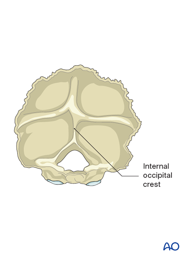
The thickest part of the cranium is the dense ridge which runs vertically in line with the internal occipital crest.
The thickness of this crest is 11.5–15 mm in males and 10–12 mm in females and it provides the best bone stock for screw purchase.
As you move laterally, this crest becomes thinner, and around 7–8 mm laterally to the midline, the bone thins out to a thickness of only 5–6 mm.
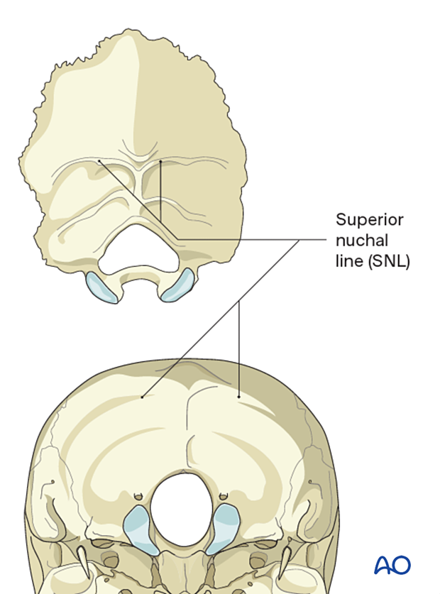
Another landmark with thicker bone is the superior nuchal line which runs horizontally.
2. Plate application
Use templates centered in the midline on the posterior aspect of the occiput to determine the optimal size and shape of the plate.
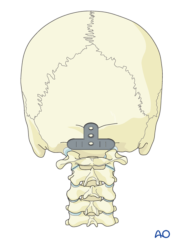
Once the optimal plate is chosen, mark the location of the central cranial screw entry point with the plate in place.
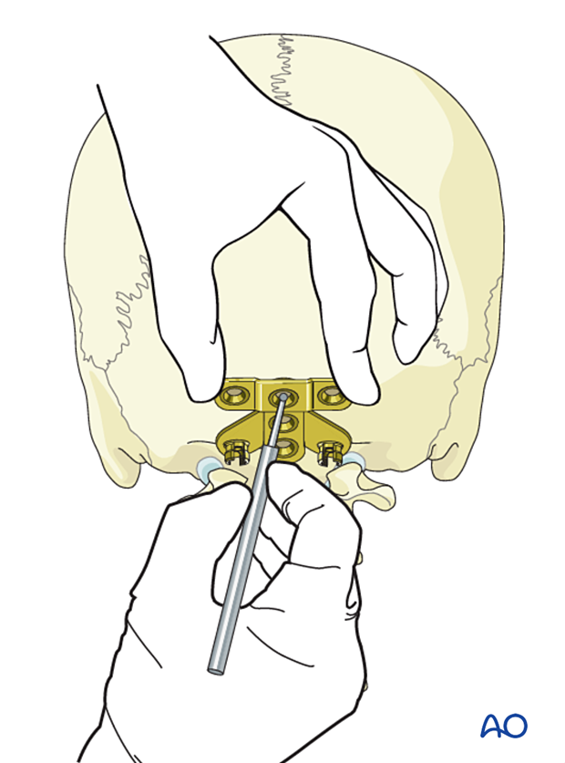
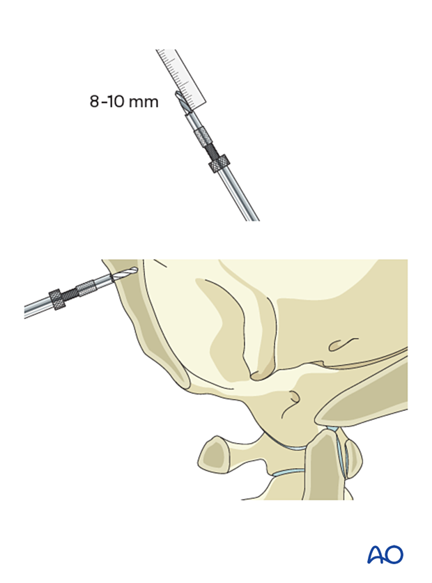
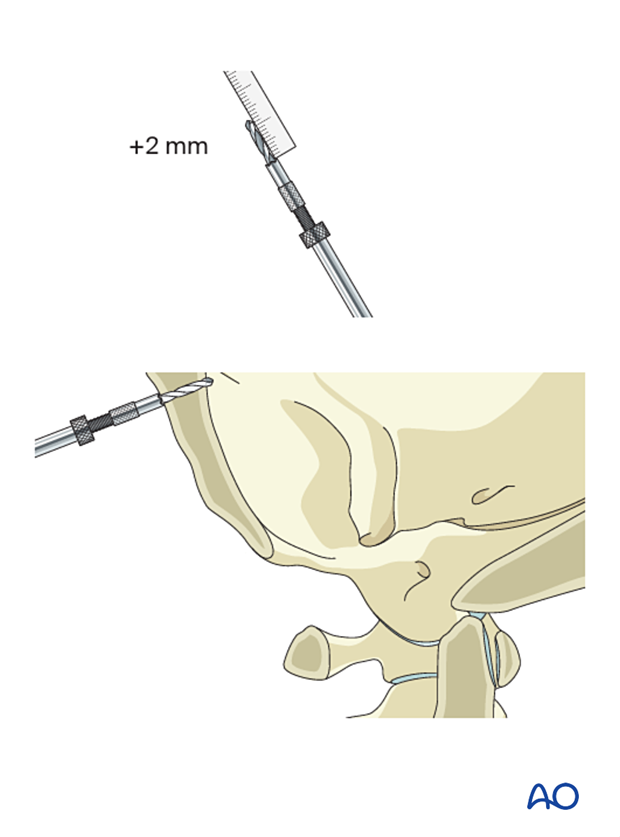
Set the drill guide to 8 mm (female) or 10 mm (male) and drill the central cranial screw hole.
Probe the screw hole to verify that the anterior cortex is still intact.
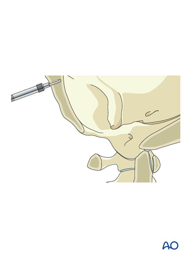
If intact, continue drilling in 2 mm increments until the anterior cortex is penetrated.
Insert a screw of appropriate length through the plate into the predrilled hole.
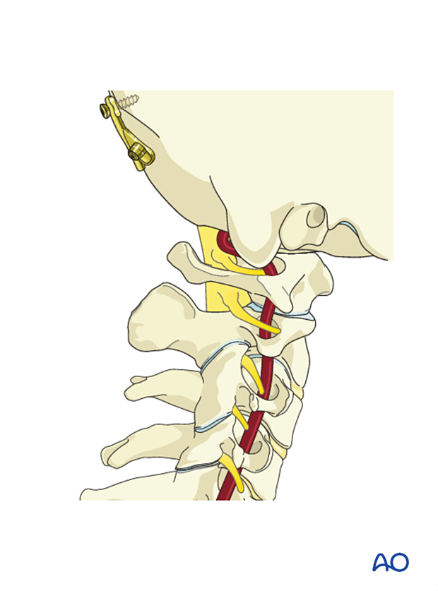
After insertion of the first screw, there is enough flexibility in the system to allow for adjustments. Ensure the plate is flush with the skull and that it is level.
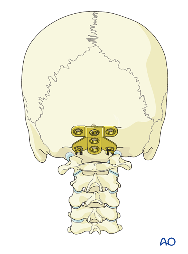
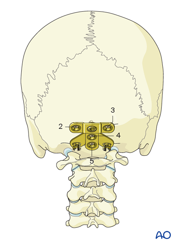
Insert the remaining screws in the order 2–5, using the same drill technique as for the first screw, ensuring bicortical purchase.
However, take care during drilling of the lateral holes (2 and 3) as the bone will be thinner than in the midline (4 and 5).
3. Cervical screw fixation
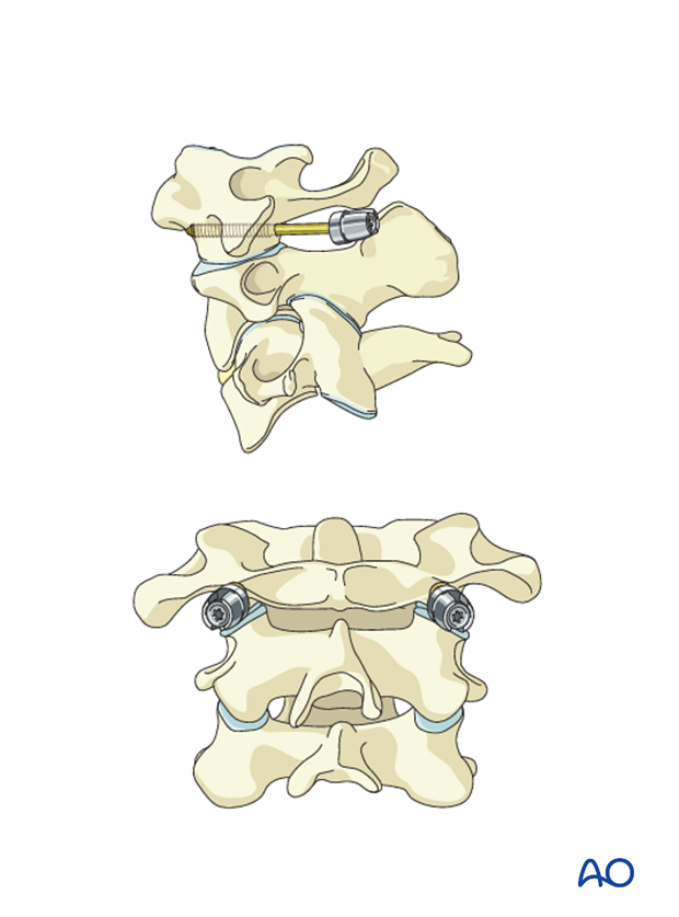
C1 instrumentation
The C1 level is rarely included in the instrumentation for C1 and C2 tumors.
However, an uncompromised lateral mass may be instrumented upon the surgeon’s preference.
C2 instrumentation
For C1 tumors, C2 is instrumented bilaterally.
For C2 tumors, the C2 level is rarely included in the instrumentation. However, if the tumor is unilateral, the contralateral side may be instrumented upon the surgeon's preference.
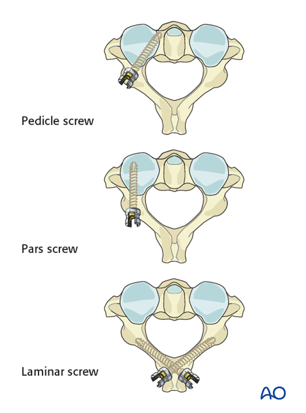
For C2 fixation, the following options are available (in order of preference):
Consideration can be given to using pedicle or laminar screws when doing an occiput to C2 fusion, as the starting point for the pars screws may often compromise the facet joint.
C3 and C4 instrumentation
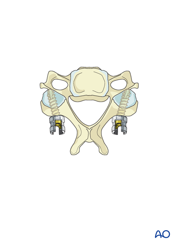
Fixation can be achieved with either lateral mass screws, pedicle screws, or a combination of the two.
Because lateral mass fixation is generally sufficient and carries less risk, pedicle screw fixation is limited to rare cases where lateral mass fixation would be insufficient or is not possible.
4. Alignment in the occipital cervical region
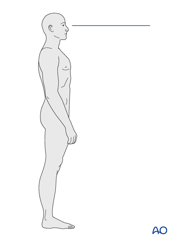
Align the head to allow for a horizontal gaze once the fusion is complete. Bend the rod accordingly.
Use the preoperative X-ray as a guide to properly align the occipitocervical junction during fusion.
5. Fusion
Decortication
Decorticate the lamina, facets, and posterior aspects of the skull.
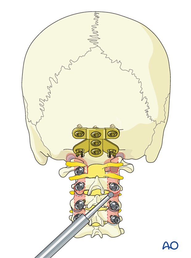
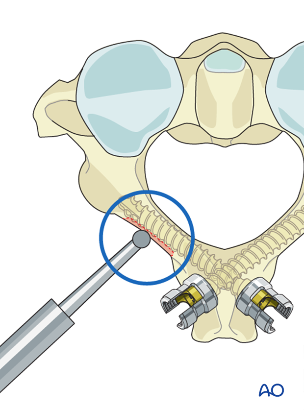
When using laminar screw fixation at C2, care must be taken not to decorticate deeply, as this might compromise screw fixation.
Rod application
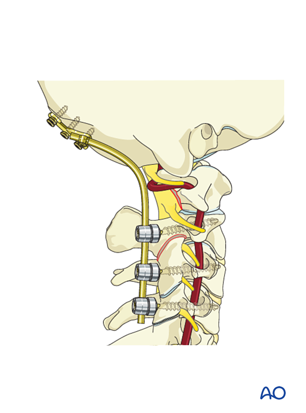
Insert both rods when correct alignment is verified.
Grafting
Place bone grafting material against the decorticated elements of the spine.


