Anterior odontoid screw
1. Introduction
Screw options
For this procedure, either one or two screws can be used.
Two screws provide higher rotational stability. A one-screw technique is generally sufficient for younger patients with good bone quality.
Measurement of the odontoid diameter will determine whether one or two screws are technically feasible.
A lag screw technique should not be used in osteoporotic bone due to the possibility of screw perforation.
In osteoporotic bone, the following options can be utilized:
- Bone cement can be injected into the C2 body to increase screw anchorage
- Anterior transarticular C1-C2 screw fixation
Specialized kits for anterior odontoid screw fixation are available; however, we will here describe the use of standard implants to show the principles.
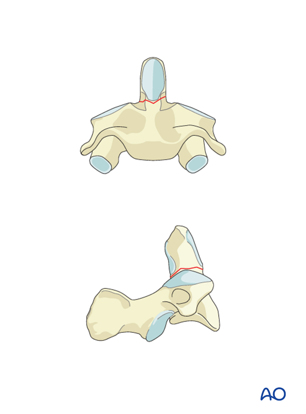
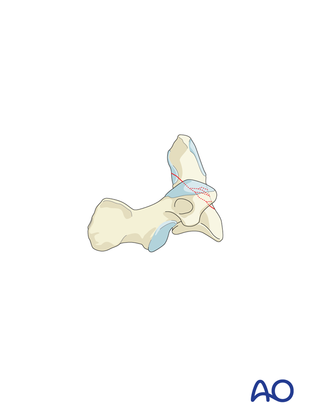
This procedure is contraindicated for fractures running from anterior caudal to posterior cranial. This is because when the screw is inserted and tightened the fragment may slide inferiorly.
Imaging
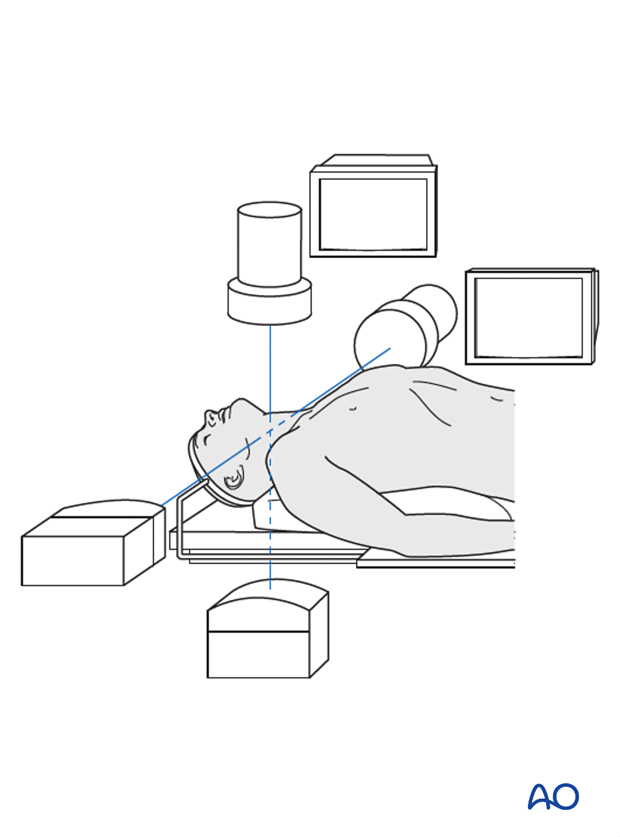
The use of two image intensifiers is ideal to identify the odontoid process in the true AP and true lateral projections. Using just one image intensifier is not recommended due to the high risk of failure.
2. Reduction
It is essential for the success of this procedure that the fracture is anatomically reduced before the surgical access.
In a flexion fracture, with an anterior displacement of the dens, reduction must be achieved with the neck in extension.
In an extension fracture, with a posterior displacement of the dens, reduction must be achieved with the neck in flexion.
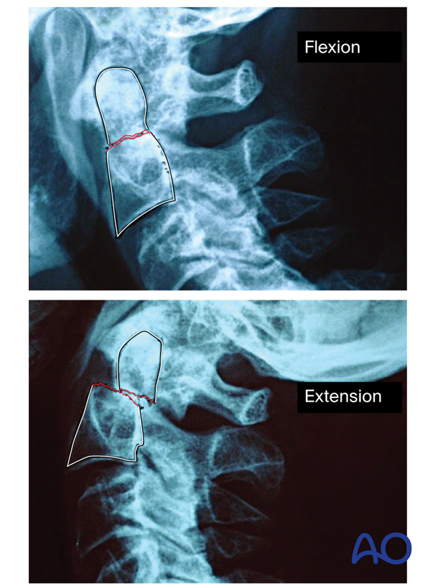
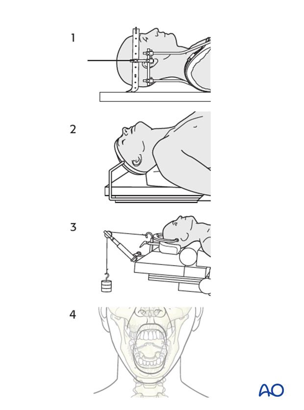
The reduction can be performed with the following methods:
- Using halo traction preoperatively
- Placing the head in an extended or flexion position as mentioned above intraoperatively
- Using a Mayfield clamp or a similar tool intraoperatively
- Pushing directly on the anteriorly displaced C1/2 segment through the mouth with the index finger in the case of a persistent anterior displacement
3. Preparation
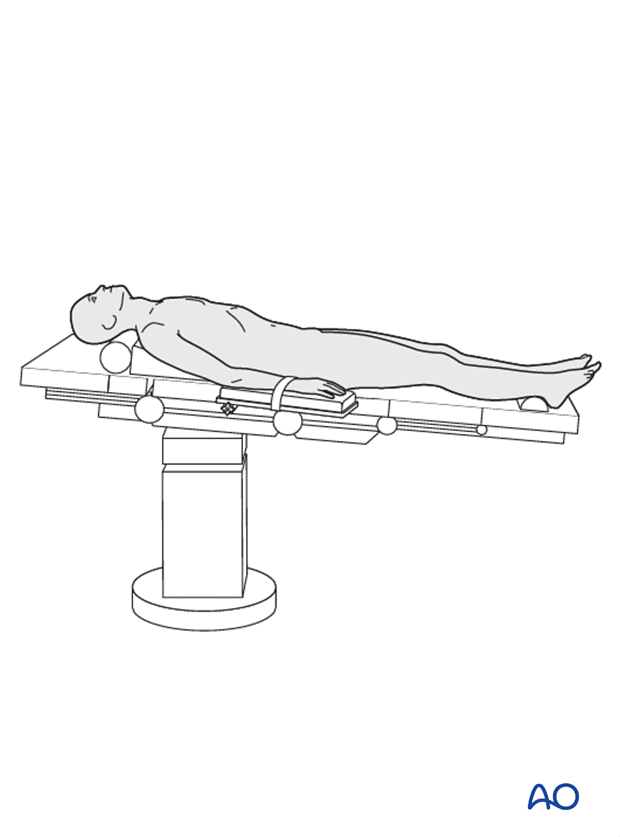
The patient is placed supine. The head is placed in an extended or flexion position according to the fragment displacement, to reduce the fracture and to facilitate the insertion of the screws.
4. Approach
An anterior approach is used. Right-handed surgeons should access through the patient's right side and vice versa.
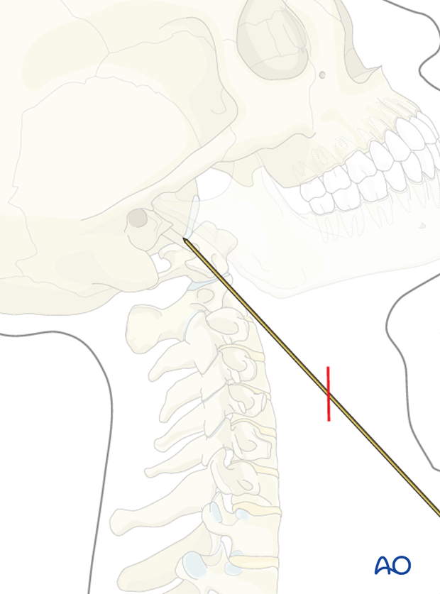
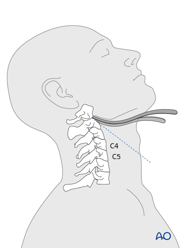
The placement of the incision is determined by placing a long K-wire along the side of the neck in the intended direction of the screw and viewing on the image intensifier. The transverse incision can then be made in the neck where the K-wire is likely to exit the skin (in most cases at the C4/5 level).
To better visualize the screw entry point, two Hohmann retractors or specially curved radiolucent retractors are inserted on either side of the odontoid (dens) to expose the body of the axis.
5. Option 1: Conventional screw insertion
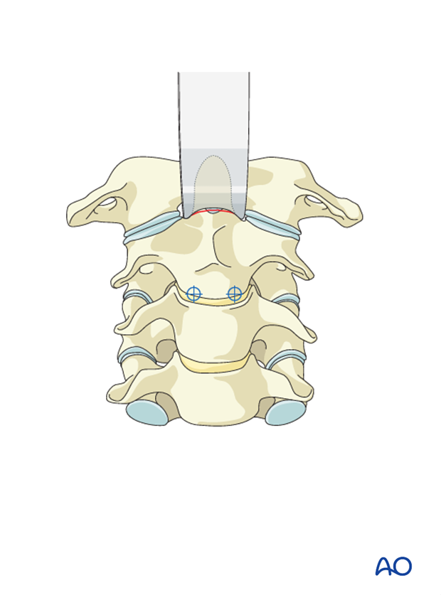
Screw entry point
The screw point is located in the anterior part of the inferior C2 endplate. To access the entry point, the drill sleeve is placed on the C2–C3 disc. In osteoporosis, the entry point can be chosen in the C2–C3 disc.
Trajectory
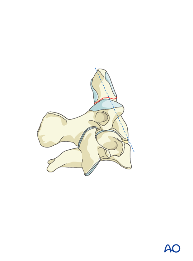
In the sagittal plane, the screw should be angled slightly posteriorly to exit at the posterior half of the odontoid’s tip (so it is a bicortical screw).
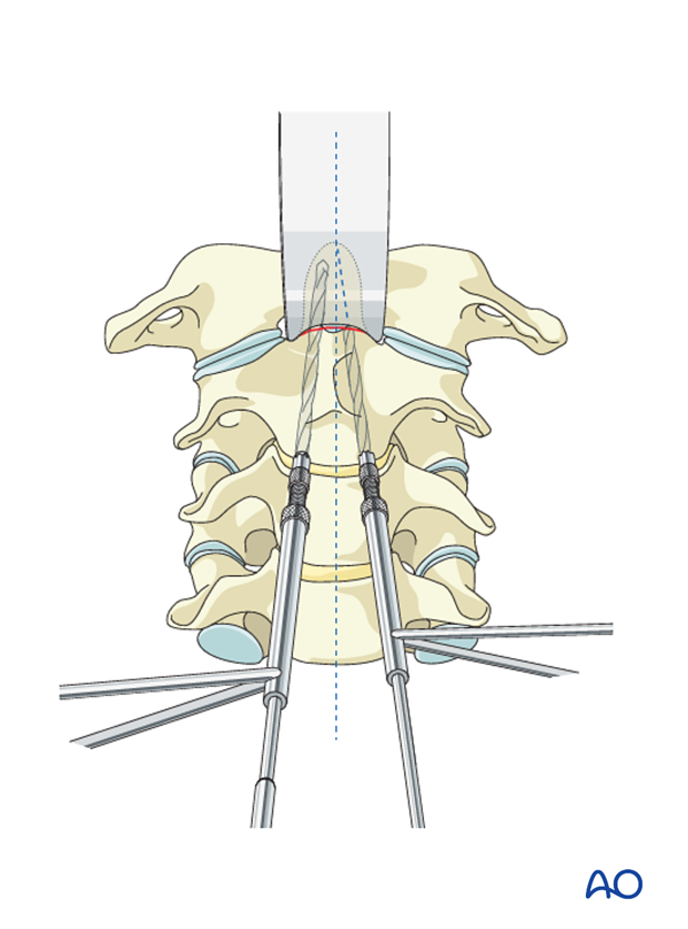
In the frontal plane, the drill should be angled a few degrees toward the midline. A second drill is inserted in the same manner.
Drilling
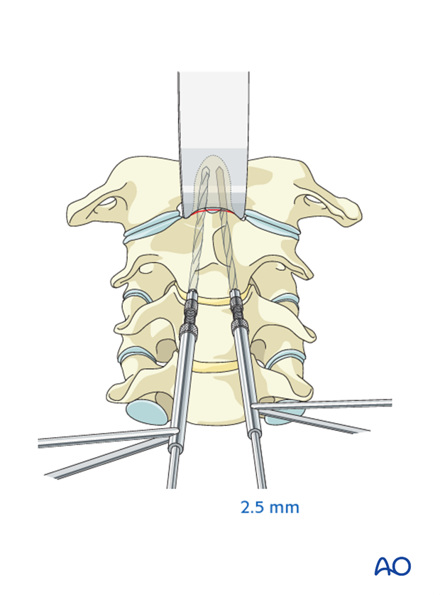
The screw holes are drilled using a 2.5 mm drill bit.
It is absolutely essential that tissue protectors are used when drilling and tapping to avoid damaging vital structures.
If fully threaded screws are used, one drill bit is removed, and the entire hole in the distal fragment is overdrilled with a 3.5 mm drill bit.
If double-threaded screws are used, overdrilling is not necessary.
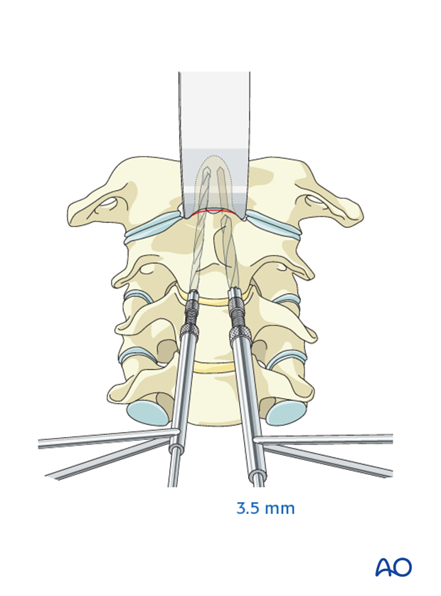
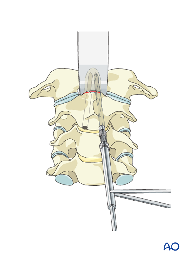
It is essential to leave one drill bit in position to maintain reduction.
Screw insertion
The depth of the hole to the tip of the odontoid is measured and tapped, and a 3.5 mm cortex screw of the appropriate length is inserted.
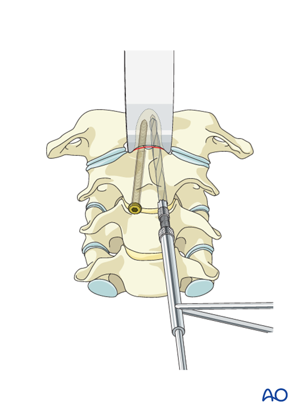
The second screw is inserted by applying the same technique.
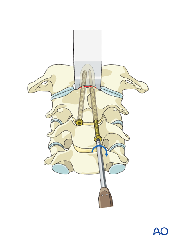
6. Option 2: Cannulated screw insertion
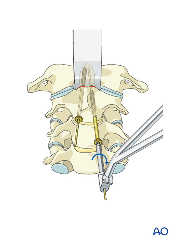
Using lateral image intensifier control, a 20 cm long, 1.2 mm K-wire is inserted in a sagittal direction on each side following the same entry point and trajectory as the screws described above.
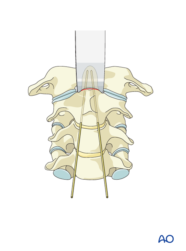
The length of the K-wire in the bone is measured with the special ruler, indicating the length of screw required, typically 38–42 mm.
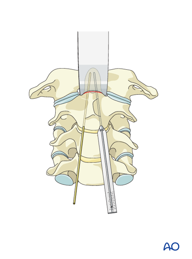
To allow the self-drilling screw to start entering the bone in the near cortex, the cortex is perforated with the special cannulated countersink.
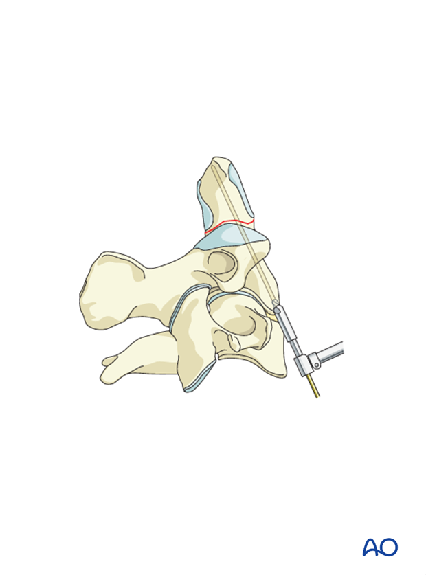
Odontoid-type cannulated screws of the appropriate length are inserted.
During the insertion of the cannulated screw, it is essential to observe this procedure on the lateral image intensifier to ensure that the K-wire does not advance superiorly.
7. Option 3: Single screw insertion
The screw point is located in the midline of the inferior C2 endplate. To access the entry point, the drill sleeve is placed on the C2–C3 disc. In osteoporosis, the entry point can be chosen in the C2–C3 disc.
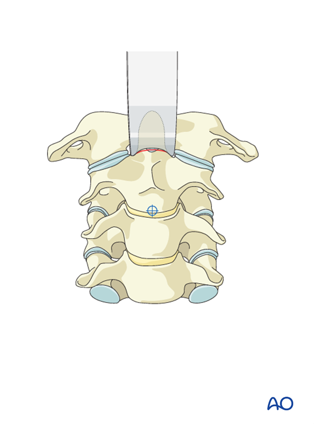
In the sagittal plane, the screw should be angled slightly posteriorly to exit at the posterior half of the odontoid’s tip (bicortical).

Using lateral image intensifier control, a 20 cm long, 1.2 mm K-wire is inserted.
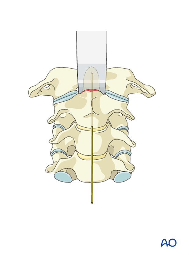
The length of the K-wire in the bone is measured with the special ruler, indicating the length of screw required, typically 38–42 mm.
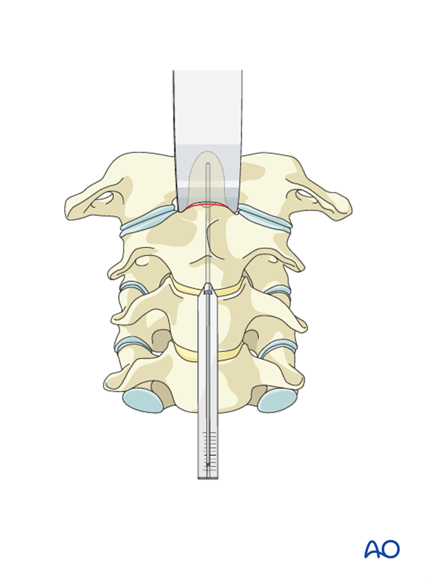
To allow the self-drilling screw to start entering the bone in the near cortex, the cortex is perforated with the special cannulated countersink.
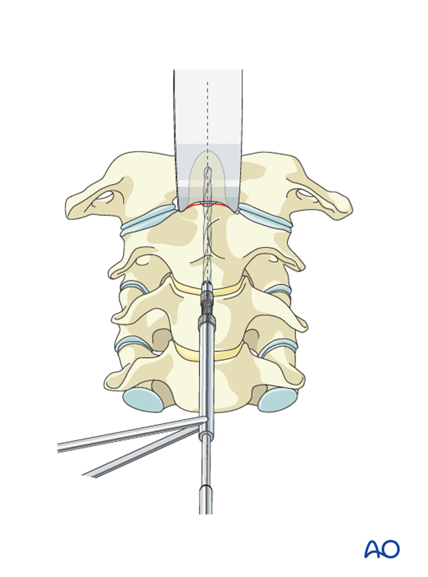
An odontoid-type cannulated screw of the appropriate length is inserted.
During the insertion of the cannulated screw, it is essential to observe this procedure on the lateral image intensifier to ensure that the K-wire does not advance superiorly.
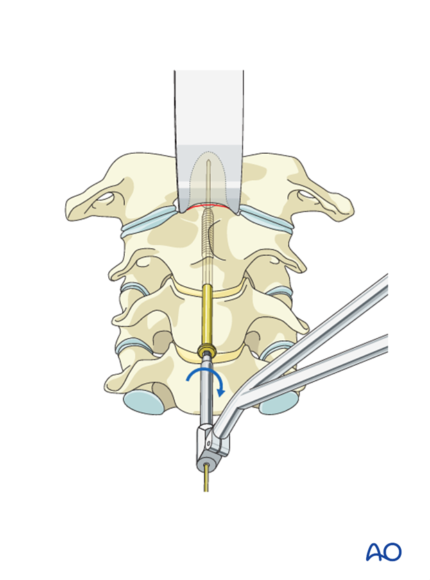
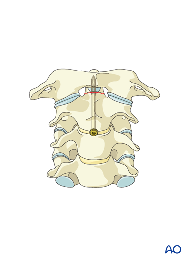
The K-wire is removed.
8. Aftercare
Patients are made to sit up in bed in the evening after the operation.
A collar is commonly used following surgical stabilization to moderate patient activity.
The purpose of a collar is to prevent ranges of motion outside of limits deemed favorable for fracture healing. The collar is optional.
Patients with intact neurological status are made to stand and walk on the first day after surgery. Patients can be discharged when medically stable or sent to a rehabilitation center if further care is necessary. This depends on the comfort levels and presence of other associated injuries.
Patients are generally followed with periodical x-rays at 6 weeks, 3 months, 6 months, and 1 year.
