Open reduction; screw fixation
1. General considerations
Fixation principles for the radial head
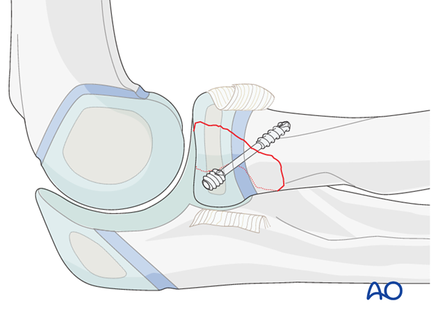
Choice of fixation depends on the size of the fragment and on the degree of comminution. A lag screw or screws, or a headless screw with variable pitch, will provide the most stable fixation because compression can be achieved.
For smaller fracture fragments K-wires may be used, or bioabsorbable pins if available.
Because the radial head is completely covered by articular cartilage the screw heads must be countersunk just below the level of the articular cartilage.
The screw tip must not protrude medially, as it will contact the ulna and interfere with supination/pronation.
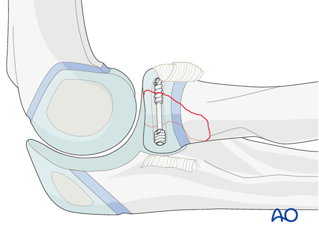
In the last two years of growth do not hesitate to place implants across the growth plate and into the metaphysis if required to achieve fracture stability.
2. Screw positioning
For the insertion of the screws, choose a location in the radial head that causes the least compromise of full pronation and supination (see below). Insert the screw(s) as perpendicularly to the fracture plane as possible.

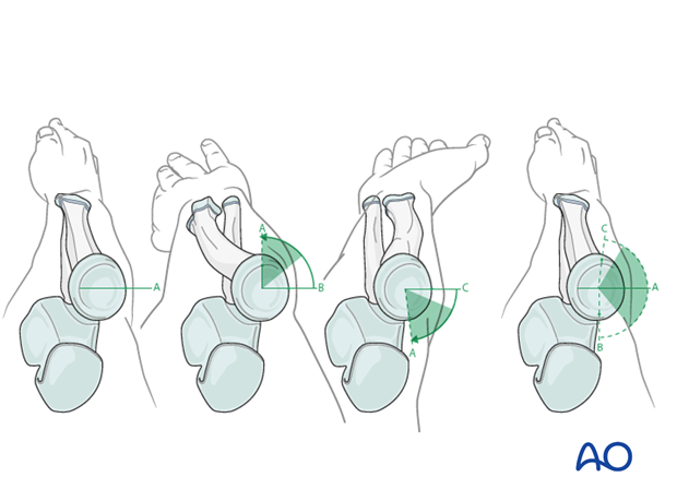
Safe zone for screw insertion
To determine the location of the “safe zone”, place reference marks along the radial head and neck, to mark the midpoint of the visible bone surface. Place three such marks with the forearm in neutral rotation (A), full pronation (B), and full supination (C) as shown in the illustration. The posterior limit of the safe zone lays halfway between the reference marks A and B made with the forearm in neutral rotation and full pronation. The anterior limit lays nearly two thirds of the distance between the neutral mark A and the mark made in full supination C.
Note: The nonarticulating portion of the safe zone for the application of implants to the radial head (or safe zone for prominent fixation) consistently encompasses a 90° angle localized by palpation of the radial styloid and Lister’s tubercle.
3. Choice of implant
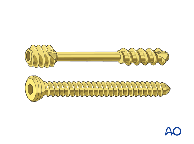
1.5 mm up to 2.7 mm screws, or headless compression screws (Herbert or similar screws) are used.
With smaller fracture fragments or higher degrees of comminution, fixation with K-wires or bioabsorbable pins may be preferred.
4. Patient preparation and approach
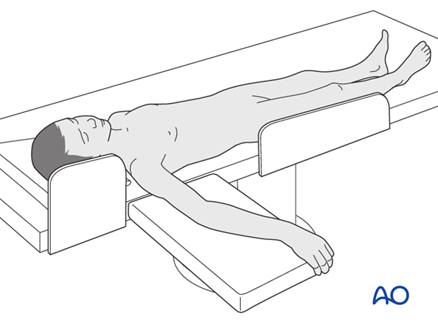
Patient preparation
This procedure is normally performed with the patient in a supine position.
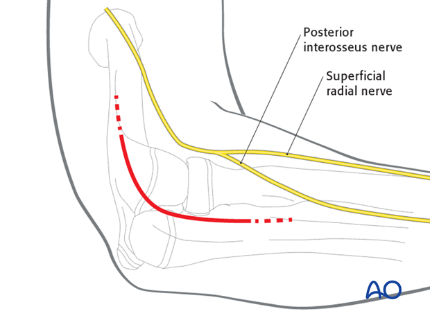
Approach
For this procedure a lateral approach is normally used.
5. Reduction and preliminary fixation
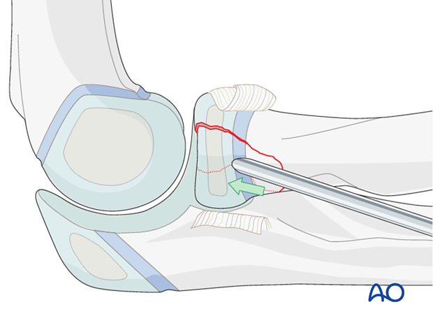
Reduction of stable fractures
In minimally displaced and stable fractures, there is no need to open the fracture site. Use a tamp to correct the displacement.
Reduction of unstable fractures
In unstable fractures, open the fracture site to clear out soft tissue, hematoma and interposed fragments.
Expose the fracture ends with minimal soft-tissue dissection.
If the radial head has been dislocated posteriorly, confirm that it is satisfactorily reduced to the capitellum.
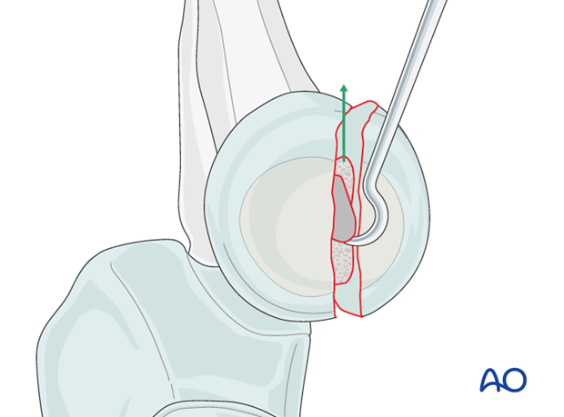
Reduction is achieved directly.
If the annular ligament is still intact, cut and retract it to achieve better access to the fracture site.
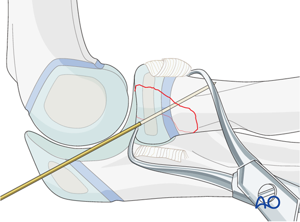
Reduce and provisionally fix the fracture with the help of small pointed reduction forceps and one or two K-wires.
Anticipate the final screw position prior to temporary K-wire placement.
6. Headless compression screw
Insertion of guide pins
Ideally direct the screw perpendicular to the fracture plane.
Guide pins for the screws are used to achieve preliminary fixation.
If one screw is used place the guide pin centrally in the small fragment. If two screws are planned place both guide pins before inserting the first screw.
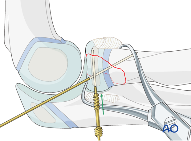
Insertion of screw
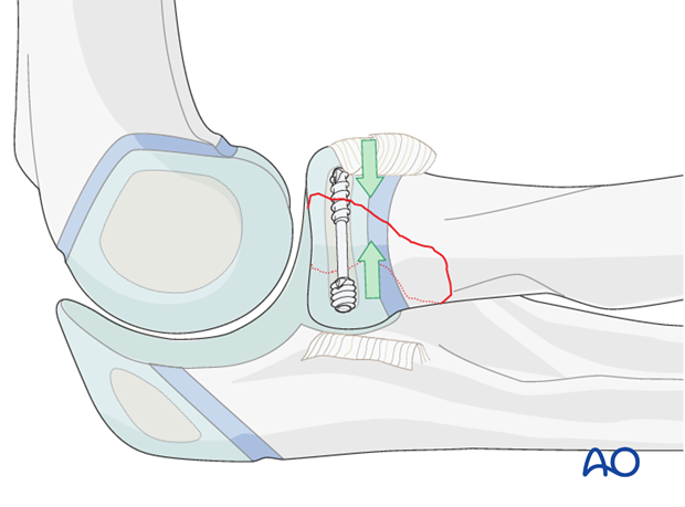
When headless compression screws (eg Herbert or HCS) are used, there is no need for countersinking as the screw head engages inside the bone.
Compression is based on variable thread pitch. The distal threads should therefore cross the fracture and completely engage the opposite fragment.
7. Alternative: lag screw
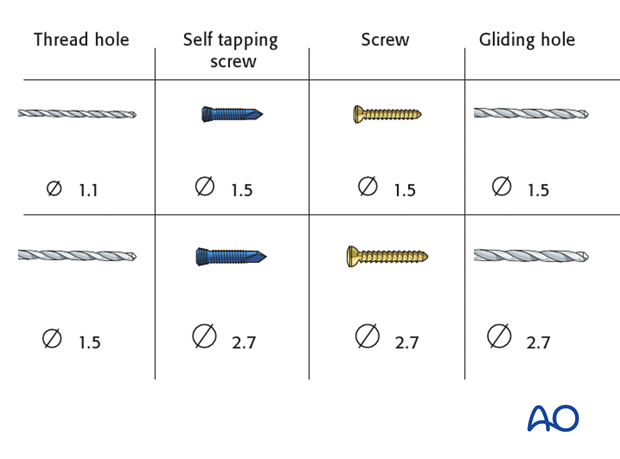
Screw and drill sizes
Plan the number and location of screws.
Drilling
Drill a gliding hole into the free fragment with the appropriate drill, determined by the screw size.
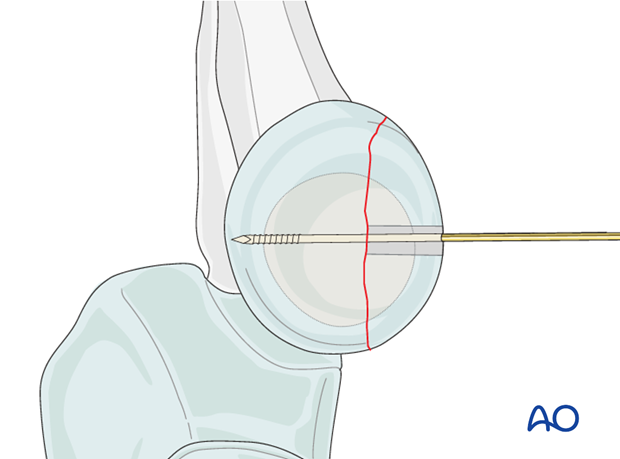
Insert the appropriate drill sleeve into the gliding hole until it reaches the fracture plane.
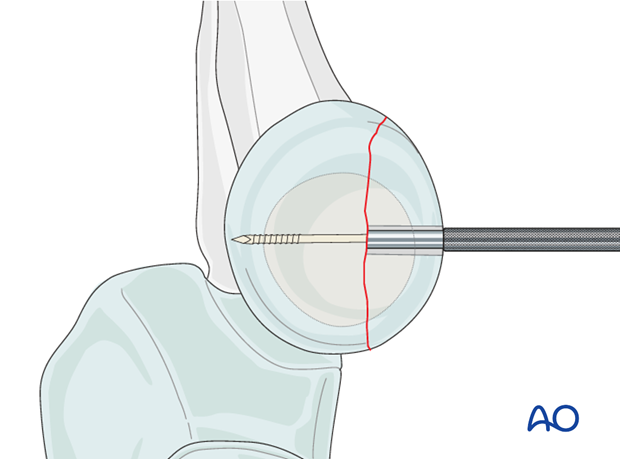
Drill the epiphysis of the intact radial head with the appropriate drill bit.
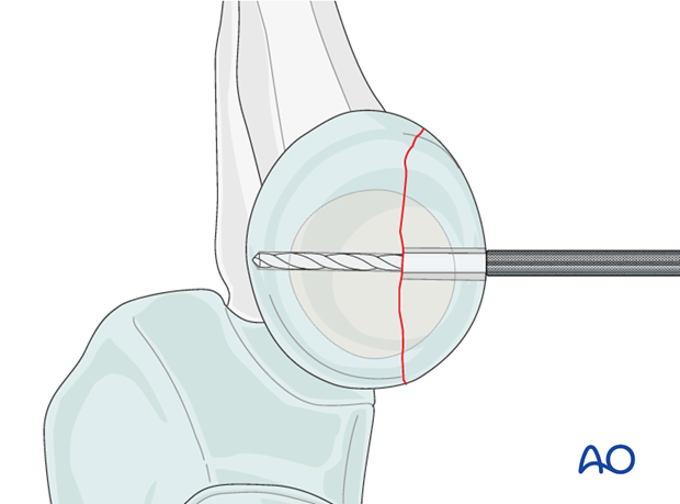
Countersinking and measuring
It may be necessary to countersink the cartilage covering the free fragment to prevent protrusion of the screw head.
Measure the depth of the hole and place the screw. If self-tapping screws are not available, tap the far epiphysis with the appropriate cortical tap and protection sleeve.
Note: Always measure after countersinking to prevent penetration of the screw tip into the joint.
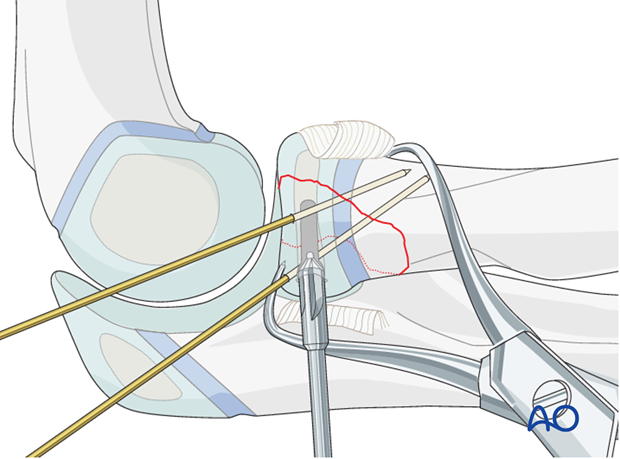
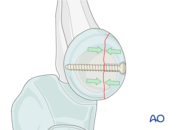
Lag screw insertion
Closely observe the compression effect on the fracture line while tightening the lag screw.
Any K-wire(s) should be removed just before the final tightening of the screw.
Second lag screw
If fragment size permits, a second lag screw will improve strength of fixation. Insert it as described for the first screw.
Note: Check reduction and screw length with supination/pronation exam. The screws should not obstruct rotation.

8. Fixation of small fragments
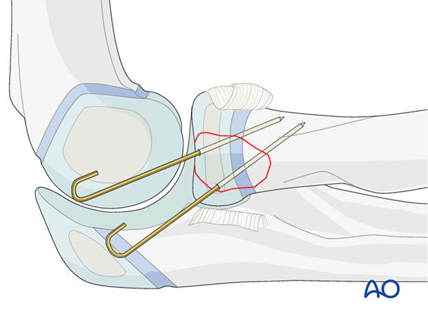
A fragment that is too small or comminuted to be fixed by a screw can be stabilized by one or two K-wires. If two K-wires are used they should diverge.
If K-wires are used they are typically bent and cut and left beneath the skin. They must be removed before full motion can be restored.
Bioabsorbable pins may be used instead to avoid a second operation for K-wire removal.
Very small fragments may require excision.
9. Ligament repair and wound closure
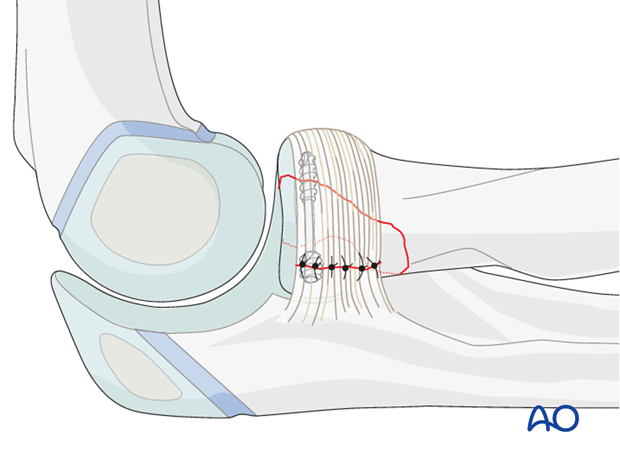
Repair the annular ligament using non-absorbable sutures.
Close the wound in layers with resorbable sutures.
10. Final assessment
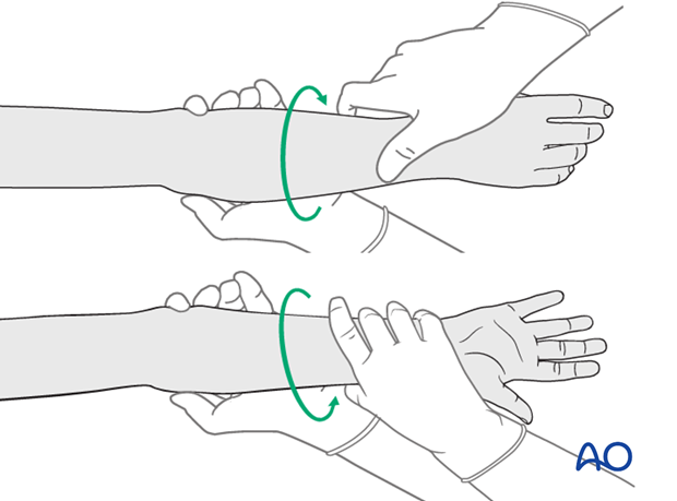
Check supination/pronation. The fixation should be stable. Crepitus or restricted motion should be absent.
Check fracture reduction and fixation with image intensifier or x-ray.
11. Aftercare following screw or K-wire fixation
Immediate postoperative care
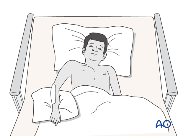
Whilst the child remains in bed, the elbow and forearm should be elevated on pillows to reduce swelling and pain.
They should be encouraged to use the arm.
Cast immobilization
Cast immobilization is not necessary and hinders early recovery of joint movement.
Analgesia
Ibuprofen and paracetamol should be administered regularly during the first 24-48 hours after surgery, with opiate analgesia for breakthrough pain.
Opiates should not be necessary after 48 hours and regular ibuprofen and paracetamol should be sufficient until 4-5 after injury or surgery.
The child should be examined if the level of pain is increasing or prolonged analgesia is needed.
Neurovascular examination
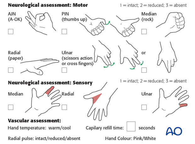
The child should be examined after casting/splinting, to ensure finger range of motion is comfortable and adequate.
Neurological and vascular examination should also be performed.
Compartment syndrome should be considered in the presence of increasing pain, especially pain on passive stretching of muscles, decreasing range of active finger motion or deteriorating neurovascular signs, which is a late phenomenon.
See also the additional material on complications and postoperative infections.
Compartment syndrome
Compartment syndrome is a possible early postoperative complication that may be difficult to diagnose in younger children.
The presence of full passive or active finger extension, without discomfort, excludes muscle compartment ischemia.
If there are signs of a compartment syndrome in a child in a cast or splint:
- Remove or split constrictive dressings or casts.
- Elevate the limb.
- Encourage active finger movement.
- Reexamine the child after 30 min.
If a definitive diagnosis of compartment syndrome is made, then a fasciotomy should be performed without delay.

Discharge care
Discharge from hospital follows local practice and is usually possible after 1-3 days.
The parent/carer should be taught how to assess the limb.
They should also be advised to return if there is increased pain or decreased range of finger movement.
It is important to provide parents with the following additional information:
- The warning signs of compartment syndrome, circulatory problems and neurological deterioration
- Hospital telephone number
- Information brochure
For the first few days, the elbow and forearm can be elevated on a pillow, until swelling decreases and comfort returns.
The arm can be placed in a sling for a few days until the patient is pain free. Many children are more comfortable without support.
Mobilization
Early movement of the elbow and forearm should be encouraged as soon as the patient is pain free.
Formal physiotherapy is normally not indicated, but children should have a sheet of exercises to stimulate mobilization. See also the additional material on elbow stiffness.
Follow-up
AP and lateral x-rays may be taken at 3-4 weeks following injury to assess position and healing.
See also the additional material on complications and healing times.
K-wire removal
Protruding K-wires can be removed immediately after follow-up x-ray.
Buried K-wires can be removed as a day case under anesthesia. A small portion of the old incision is opened directly over the palpable tips of the bent K-wires. Wires are extracted with pliers or a heavy needle holder.
Screw removal
It is not mandatory to remove metal ware, particularly if there are no local symptoms.
Screw removal may be required if the screw head or tip causes soft-tissue irritation.
Safe removal requires an open approach using the initial incision to ensure protection of adjacent neurovascular structures.


