ORIF - Lag screws outside protection plate
1. Principles
Indications
Nonoperative treatment
Spiral fractures of the tibial diaphysis can be treated nonoperatively. However, some shortening must be expected. The initial x-ray usually shows the expected final shortening. Displacement of more than 30%, particularly for distal fractures, suggests an increased risk of secondary displacement with nonoperative treatment.
Malrotation is a risk which must be looked for and corrected, particularly during the first weeks of nonoperative treatment.
Operative treatment with a nail
Nailing is usually a good option in tibial fractures. However, in long spiral fractures, malrotation can be a problem and must be addressed by the surgeon.
Operative treatment with lag screws and protection plate
For the treatment of simple spiral fractures in the diaphyseal area, absolute stability is recommended. For this, anatomical reduction and interfragmentary compression are necessary. Interfragmentary compression is achieved with at least two lag screws, but the strength of this fixation is often insufficient for clinical use.
Protection plate
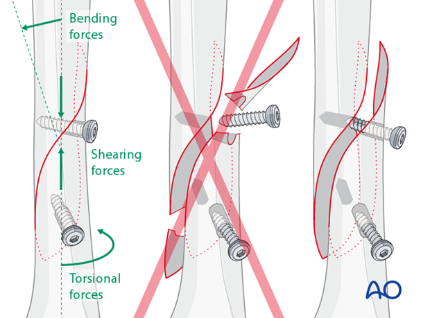
Bending, shearing and torsional forces acting on an unprotected lag screw may cause screw loosening, loss of compression, or fracture of the bone. In order to protect the lag screw from these forces, a protection plate should be applied.
2. Preoperative planning
Screw position
Lag screws should always be inserted as perpendicular as possible to the fracture plane where they cross it.
Lag screws inserted through a plate give better stability than screws outside of a plate. Whenever possible, plan the plate position so that one or two screws can be inserted through the plate and still perpendicular to the fracture.
However, in some situations, one, or both, lag screws have to be inserted outside of the plate, depending on fracture geometry and surgical access.
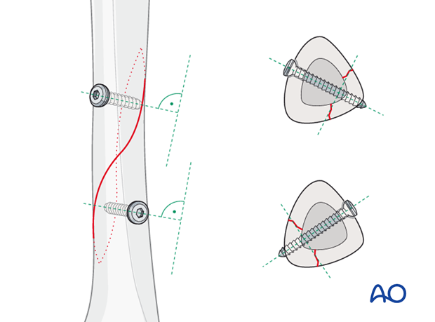
Plate location
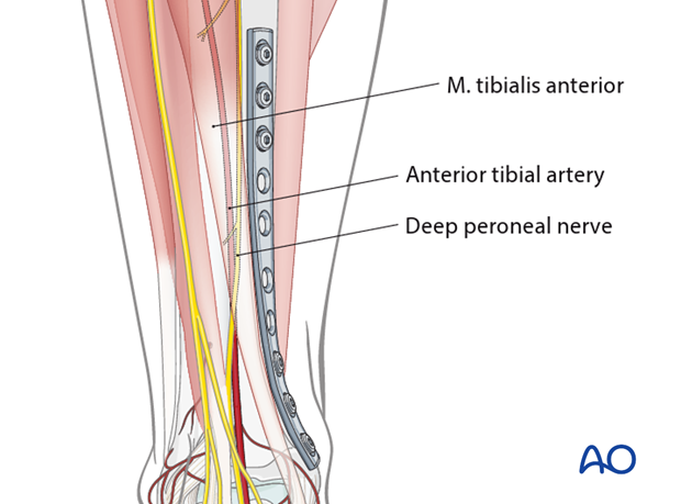
If the anteromedial skin is completely free of injury, a plate can be positioned on this tibial surface. When in doubt about the soft tissues, an anterolateral plate may have less risk of wound breakdown.
An anteromedial, subcutaneous plate does not require muscle elevation, as would be necessary anterolaterally, but with some loss of periosteal blood supply. Furthermore, this location also allows a more distal position of the plate.
The plate should be long enough to span the fracture zone, usually with at least 3 screws proximal and distal.
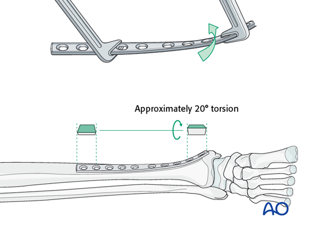
A narrow, large-fragment (4.5 mm screws) plate is usually chosen. It will need to be bent and twisted to fit the selected tibial surface.
3. Patient preparation and approaches
Patient preparation
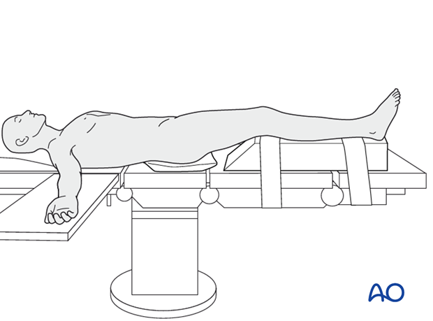
This procedure is normally performed with the patient in a supine position.
Anteromedial approach
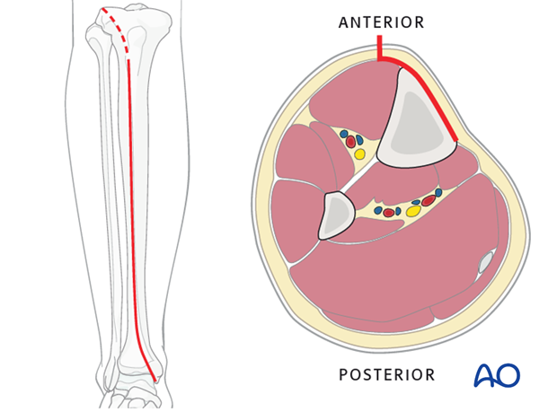
The anteromedial approach is used most commonly for fractures of the distal third tibial shaft. However, it can be used to expose the entire anteromedial surface.
It is also useful for debridement and irrigation of open fractures when an incision on the injured subcutaneous surface is to be avoided.
Anterolateral approach
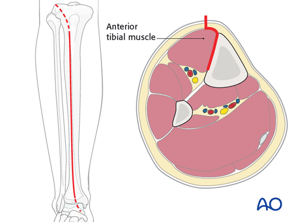
The anterolateral approach is used uncommonly, but may be necessary when the medial soft tissues are compromised.
4. Open reduction
Introduction
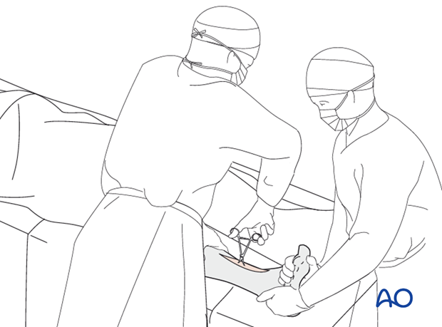
Open, or direct, reduction is necessary to achieve the required anatomical reduction.
Leave the periosteum on the bone, except elevate just enough around the fracture edges to confirm the reduction.
Pointed reduction forceps are preferred because they do less damage to the soft tissues.
Reduction
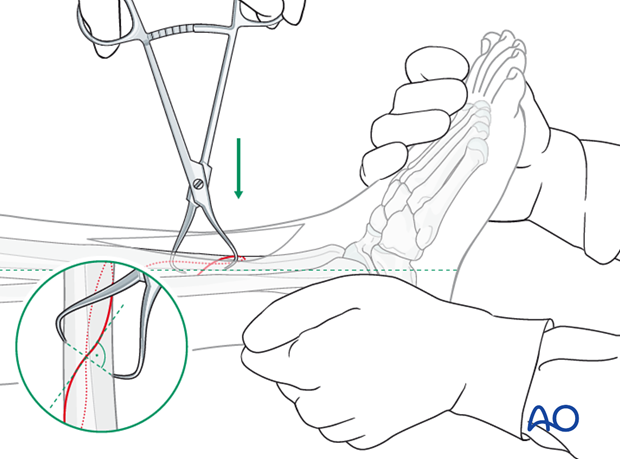
In a first step, length and rotation must be restored. This may be possible with manual traction. Otherwise, mechanical aids such as a large distractor, or bone spreader, should be considered.

In a second step, once length and rotation are restored, pointed reduction forceps are used to compress and anatomically reduce the fracture. The forceps tips should be applied perpendicular to the plane of the fracture, just like a lag screw.
5. Preparation
Introduction
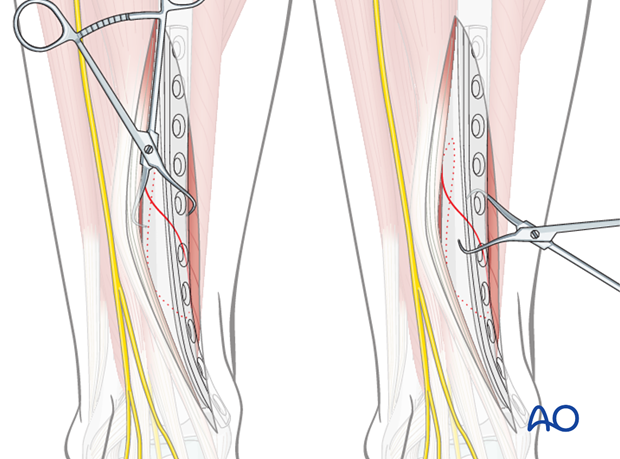
Sometimes the fracture is in a plane that makes it impossible to insert the lag screws through the plate perpendicularly to the fracture plane. In such cases, the lag screws are inserted outside of the plate. Depending upon fracture location and soft-tissue condition, the plate is then applied to either the anteromedial, or the anterolateral surface.
Provisional fixation with the pointed reduction forceps
Use the pointed reduction forceps to provisionally stabilize the fracture. Select a position for the forceps that will not interfere with the planned position of the screws, or plate.
Remember, the forceps can be placed either medially or laterally. Choose the position that allows the most stability with the least soft-tissue damage.
6. Drilling and tapping
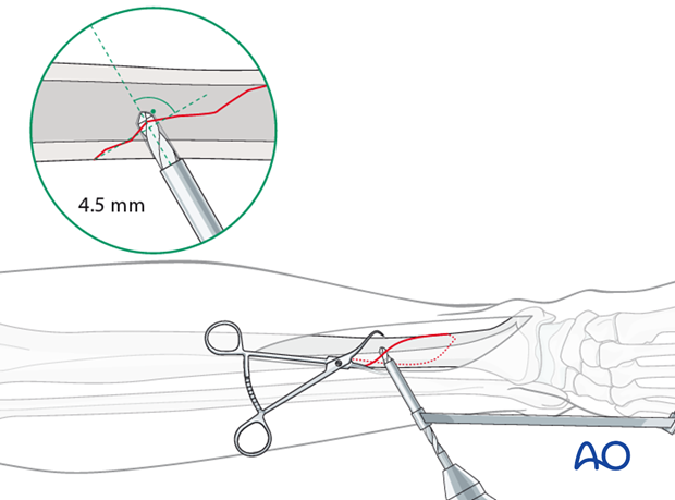
Gliding hole for the first lag screw
Using a 4.5 mm drill guide and a 4.5 mm drill bit, drill a gliding hole in the near cortex.
Ensure that the direction of the drill is as perpendicular to the fracture plane as possible.
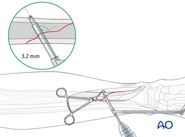
Drilling the thread hole
Insert the 4.5 mm / 3.2 mm drill into the gliding hole. Use a 3.2 mm drill bit to drill a thread hole just through the far cortex.
Countersinking in diaphyseal bone
There are two important reasons for countersinking:
- Countersinking ensures that the screw head has a maximal contact area with the bone, so that its compressive forces are widely distributed.
- A countersunk screw head is less prominent and tender.
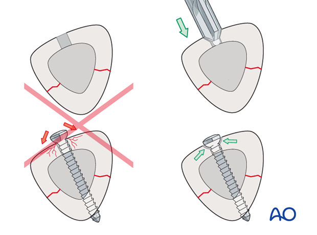
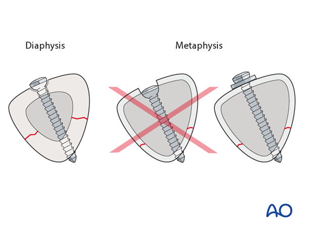
No countersinking in the metaphysis
Do not countersink the screws in the metaphysis as its cortex is very thin.
Countersinking through a thin cortex removes the bone surface on which the screw head must rest. Instead, a washer should be considered.
Measure for screw length
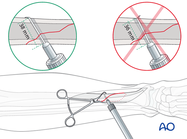
Use a depth gauge to measure for screw length.
Measure the longer side of an oblique drill hole, as shown, to ensure sufficient screw length.
A screw should protrude 1-2 mm through the opposite cortex to ensure thread purchase. However, too long a screw may be tender, or injure soft tissues.
Tap the thread hole
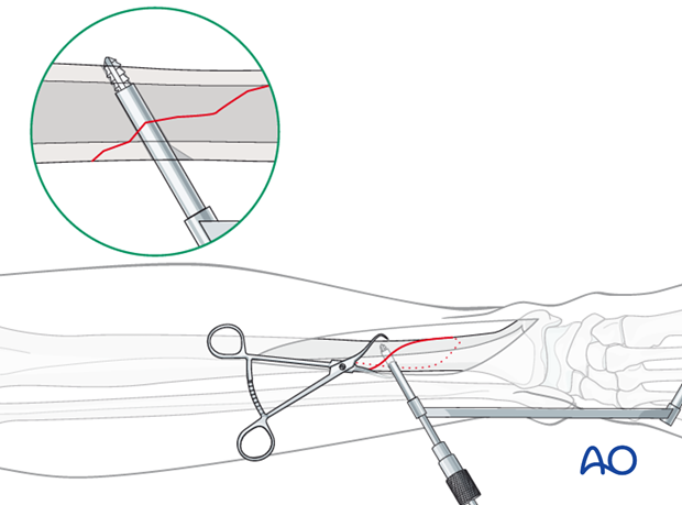
Use a 4.5 mm tap and the corresponding drill sleeve to tap the thread hole.
7. Screw insertion
Lag screw insertion
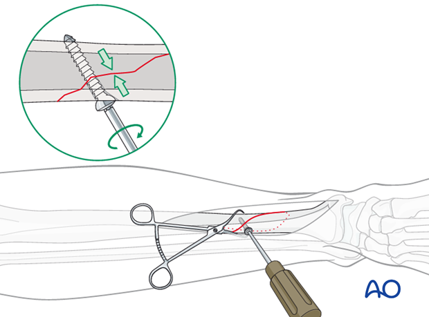
Insert the first lag screw and carefully tighten it. Ensure that the fracture remains reduced, and is compressed.
Insertion of the second lag screw
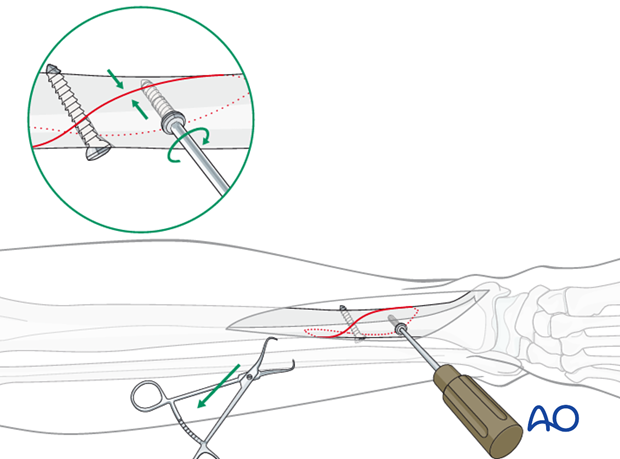
Insert the second lag screw following the same steps as for the first lag screw:
- Drill the gliding hole with a 4.5 mm drill bit and drill guide as perpendicular to the fracture plane as possible.
- Insert the 4.5 mm / 3.2 mm drill guide into the gliding hole.
- Drill the thread hole with a 3.2 mm drill bit.
- Countersink the near cortex.
- Measure for length.
- Tap the thread hole with a 4.5 mm tap.
- Insert the screw.
8. Plate placement
Plate selection and preparation
The correct length of the straight 4.5 mm DCP should allow at least 3 screw holes proximal and 3 screw holes distal of the fracture site.
Usually a 10-12 hole straight 4.5 mm DCP is used. The plate has to be twisted and bent to perfectly adapt to the shape of the anteromedial distal tibia.
Insertion of diaphyseal plate screws
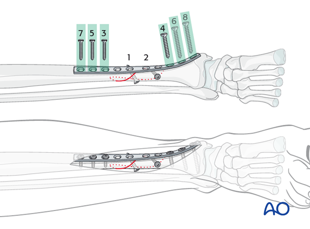
The screws closest to the fracture zone are inserted first. Insert the remaining screws alternately, working your way outwards. Remember that it is not necessary to fill every screw hole, but those closest to and furthest from the fracture must be used.
For all diaphyseal screws, use cortical screws, observing the following steps:
- Drill both cortices using the appropriate drill guide to ensure a central drill hole with the 3.2 mm drill bit.
- Measure for screw length.
- Tap both cortices using the 4.5 mm tap and appropriate drill sleeve.
- Insert the screw.
Insertion of metaphyseal plate screws
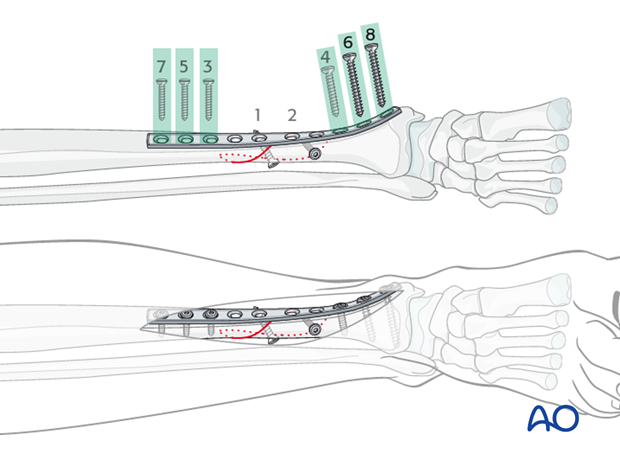
In the metaphysis, use screws with cancellous threads.
Observe the following steps:
- Drill using the appropriate DCP drill guide to ensure a central drill hole with the 3.2 mm drill bit. Do not penetrate the far cortex (or the joint).
- Measure for screw length.
- Tap just the near cortex using the 6.5 mm tap and appropriate drill sleeve.
- Insert cancellous screws and carefully tighten them.
Metaphyseal screws should be as long as possible but must not penetrate the far cortex, or the joint.
9. Postoperative care
Perioperative antibiotics may be discontinued before 24-48 hours.
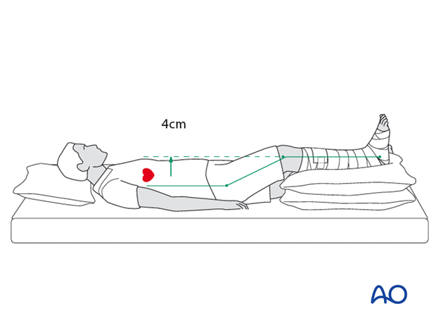
After surgery, the patient’s leg should be slightly elevated, with the leg placed on a pillow, 4 cm above the level of the heart.
Attention is given to:
- Pain control
- Mobilization without early weight bearing
- Leg elevation when not walking
- Thromboembolic prophylaxis
- Early recognition of complications
Soft-tissue protection
A brief period of splintage may be beneficial for protection of the soft tissues, but should last no longer than 1–2 weeks. Thereafter, mobilization of the ankle and subtalar joints should be encouraged.
Mobilization
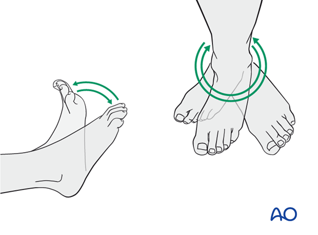
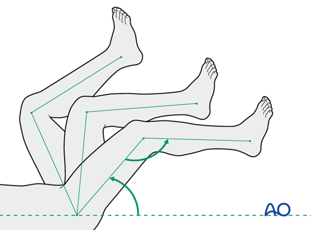
Active and assisted motion of all joints (hip, knee, ankle, toes) may begin as soon as the patient is comfortable. Attempt to preserve passive dorsiflexion range of motion.
Weight bearing
Limited weight-bearing (15 kg maximum), with crutches, may begin as tolerated, but full weight bearing should be avoided until fracture healing is more advanced (10-12 weeks).
Follow up
Follow-up is recommended after 2, 6 and 12 weeks, and every 6-12 weeks thereafter until radiographic healing and function are established. Depending on the consolidation, weight bearing can be increased after 6-8 weeks with full weight bearing when the fracture has healed by x-ray.
Implant removal
Implant removal may be necessary in cases of soft-tissue irritation by the implants. The best time for implant removal is after complete bone remodeling, usually at least 24 months after surgery. This is to reduce the risk of refracture.
10. Case
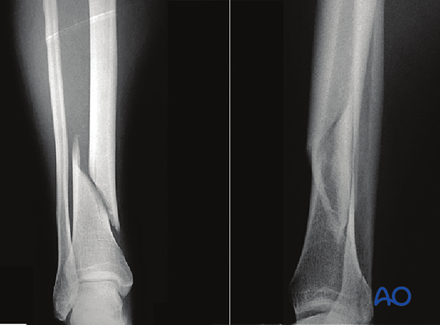
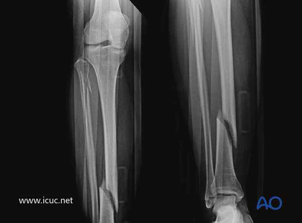
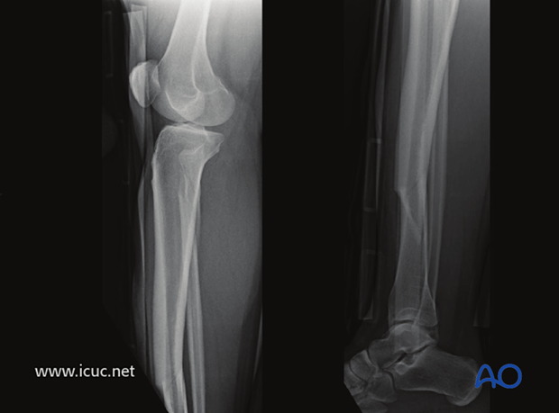
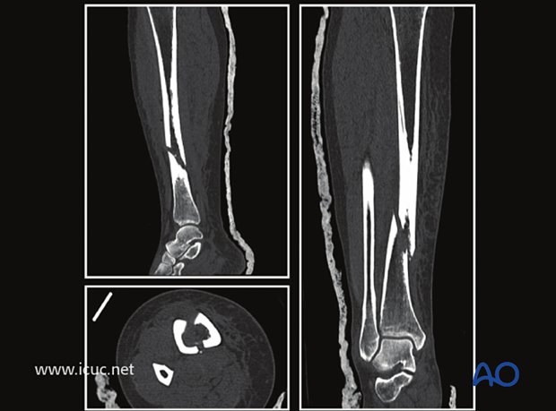
This is a simple spiral fracture of the tibial shaft with a proximal fibular neck fracture.
Lateral image of the same fracture.
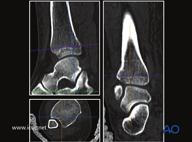
Because of the spiral nature of this fracture, many of these twisting injuries have a component of fracture that goes into the joint. A CT scan was used to assess this.
A CT scan at the malleolar level showed that the fracture did continue into the ankle joint but with minimal displacement.
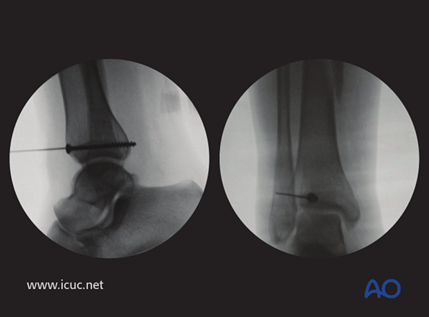
Before plating the tibia, a lag screw was placed across the fracture site just above the ankle to prevent the intraarticular component from displacing.
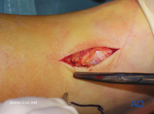
A K-wire was inserted to ensure the fracture did not displace during lag screw insertion.
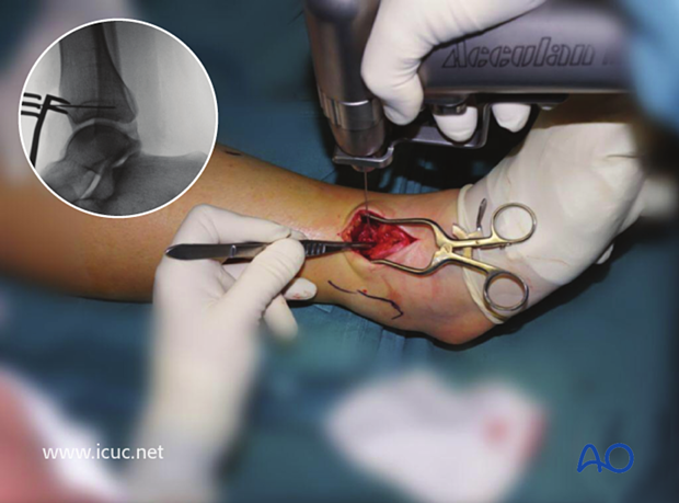
The lag screw was placed just above the joint line in the AP plane. This lag screw is probably 2 mm too long.
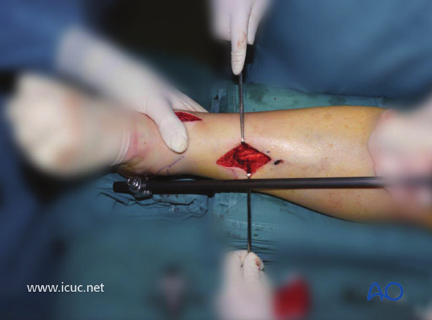
The fracture was reduced with the help of a distractor with pins in the calcaneus and proximal tibia. Note the small incision directly anterior, perpendicular to the fracture plane so that the fracture can be reduced under direct vision.
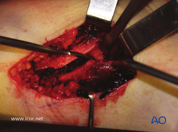
The fracture has been exposed but not yet reduced.
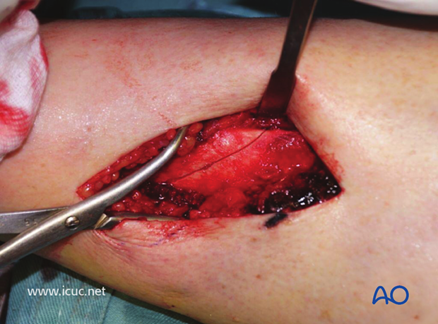
The fracture has now been reduced and held with a sharp Weber clamp.
The pilot hole for a cortical lag screw is being drilled from anterior to posterior.
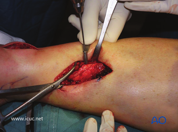
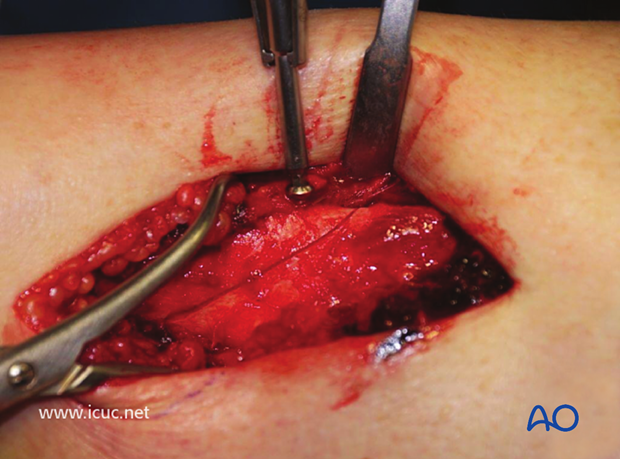
After tapping and countersinking, the cortical lag screw is inserted. Care must be taken not to overtighten it as this might create a new fracture.
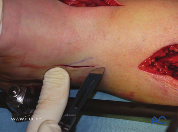
The distal incision for the MIPO plate insertion is made on the medial side, taking care not to damage the saphenous vein and nerve.
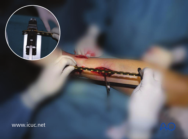
The appropriate length LCP is selected and contoured.
A small amount of distal contour allows for the medial malleolar flare.
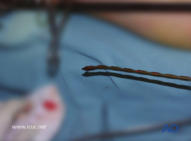
The proximal incision is made.
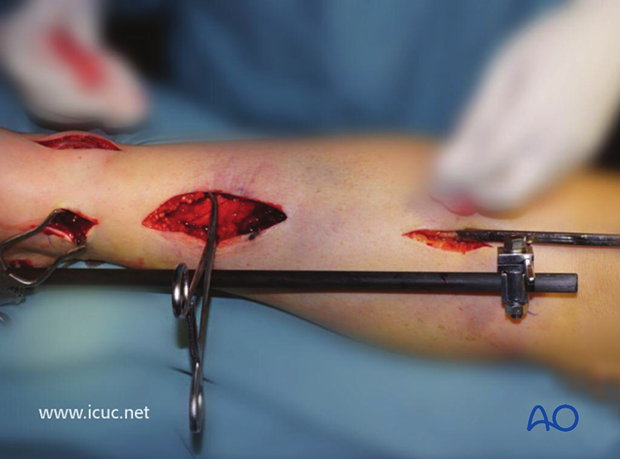
The plate is slid under the soft tissues along the surface of the bone. In this case the plate required further contouring so it was removed, adjusted and reinserted.
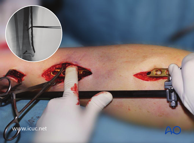
Final AP X-rays of MIO plating using the near far principle for screw placement. It is important to remember that any screw that crosses a fracture line should be used with lag technique.
As the fracture was well reduced, and held with two lag screws, the surgeon felt that only two distal screws and two proximal screws were required to achieve sufficient stability.
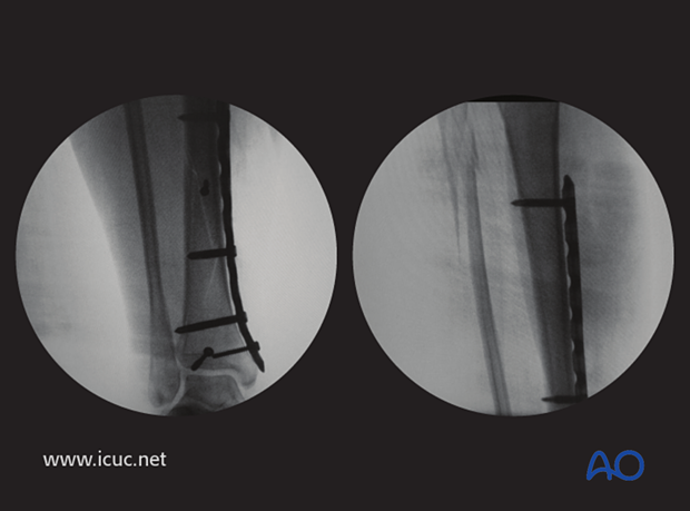
AP lateral X-rays at 6 weeks, showing the reduction has been maintained and the fracture is healing.
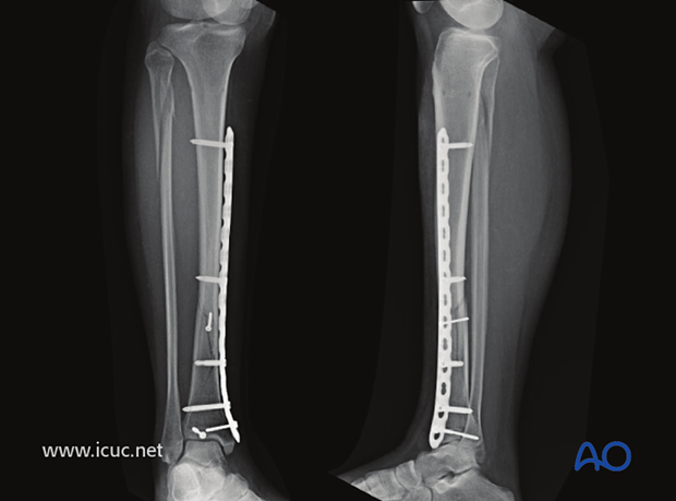
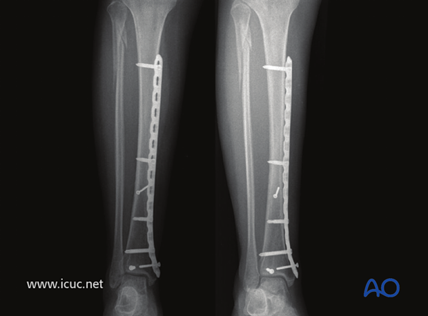
Healed tibial fracture at 6 months.
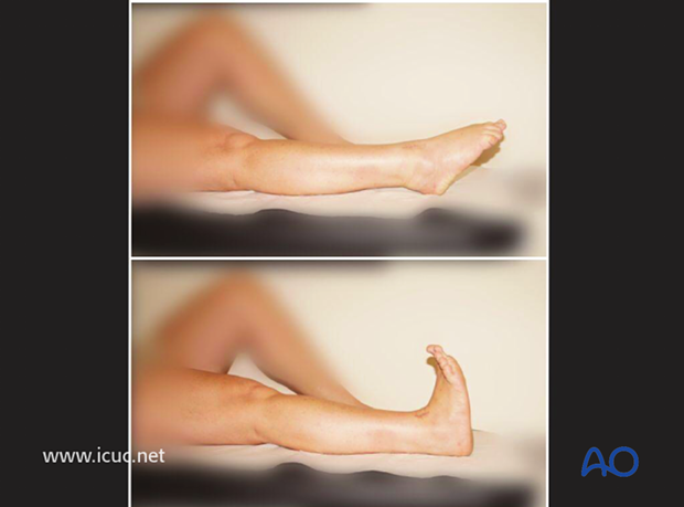
Clinical image of good outcome at 30 weeks.
