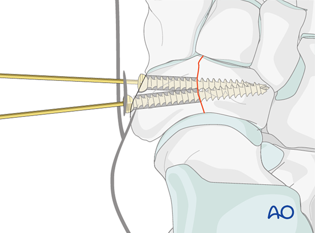
Lag screw of simple complete navicular fracture
1. Screw selection
For the procedure, a range of screws can be utilized:
- Cannulated screws
- Non-cannulated screws
- Headless compression screws
We will here demonstrate the use of cannulated and non-cannulated screws.

2. Reduction
Distraction
Both articular surfaces require visualization for accurate reduction and fixation.
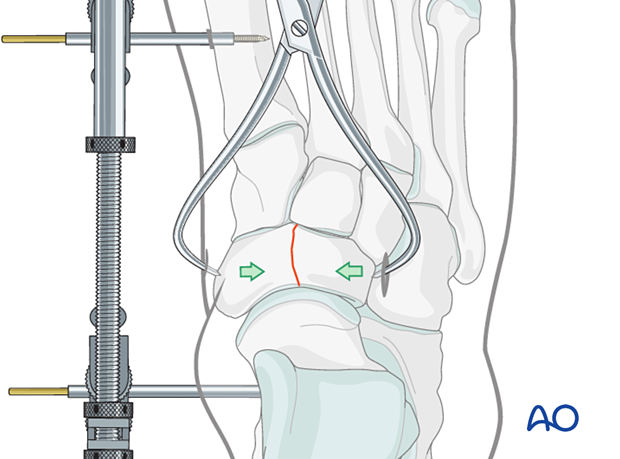
A medial-column distractor can be used.
The proximal pin is inserted into the neck of the talus through a stab incision. Image intensification can be used to ensure correct pin placement outside the articular surfaces. The correct insertion point is often located 1–2 cm posterior to the navicular tubercle.
The distal pin is inserted in the first metatarsal.
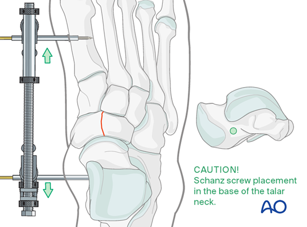
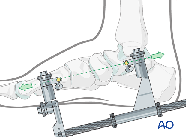
The distraction vector needs to be in line with the talus and the first metatarsal in the medial plane.
Reduction
Insert the pointed reduction forceps through two small stab incisions placed dorsomedially and dorsolaterally.
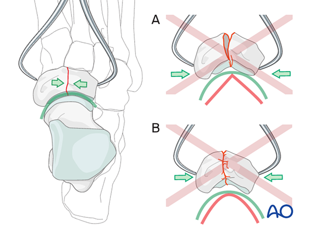
When treating fractures of the navicular, it is essential to pay attention to its concavity.
The reduction forceps tips should be positioned in such a way as to provide even compression across the fracture. Proximal positioning of the tips may lead to malreduction (A).
Reduce the fracture carefully. Do not overcompress since this will destroy the anatomical concavity of the joint surface (B).
Preliminary K-wire fixation
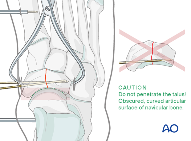
Often provisional K-wire fixation is necessary since the tip of the reduction clamp is placed precisely where you want to insert the lag screw.
If cannulated screws are used, the guide wires can be used for provisional fixation. Care must be taken in terms of K-wire trajectory to avoid joint penetration of the concave articular surface of the navicular.
If solid screws are to be used, be sure to place the K-wires so that they will not interfere with the subsequent screw placement.
Check reduction
Ensure that the joint is anatomically reduced. The reduction can be inspected under direct vision if the joint has been correctly distracted.
The articular surface congruity can be palpated with an elevator inserted dorsally if direct vision is impossible.
Also, use image intensification to check your reduction.
The resolution of the image intensifier may not be sufficient to appreciate small joint incongruities. If in doubt, get intraoperative x-rays.
3. Fixation
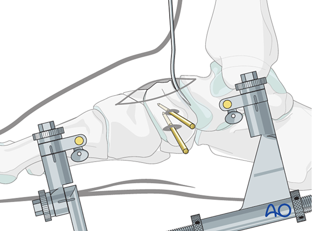
Use an image intensifier to verify the appropriate screw length.
Insert the proximal lag screw according to the standard technique. In contrast to lag screws inserted in the diaphysis, these lag screws will typically not penetrate the far cortex, as this would damage the opposite articular surface.
Afterward, insert a second lag screw in the same fashion.
The screws may be non-cannulated, cannulated, or headless compression screws.
If the bone is osteoporotic, insert a washer under the screw head to prevent it from sinking into the bone.
Remove the K-wires.
