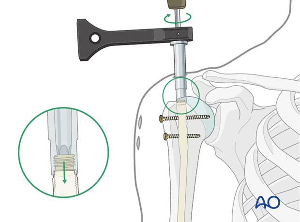
Antegrade nailing - bent nail
1. Principles
General considerations
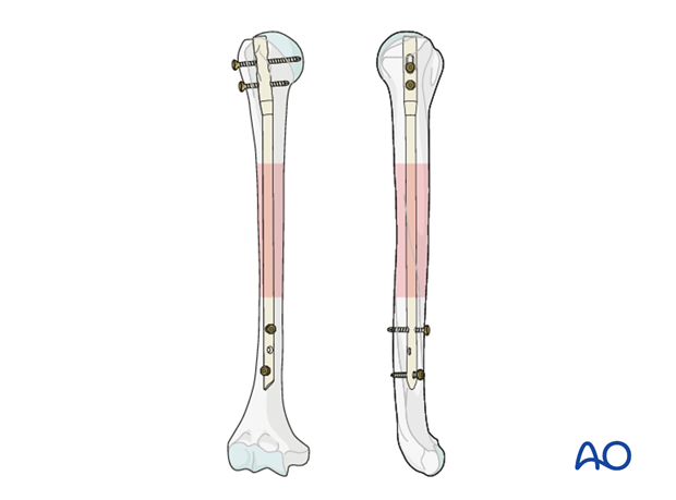
The best indications for humeral shaft nailing are fractures located between the surgical neck and approximately 5 cm above the olecranon fossa.
There are many different nails on the market; they differ in design aspects, such as bend or straight axis, entry point and locking configurations. Some nails allow compression at the fracture site.
To demonstrate the principles, the illustrations below show the use of a bent nail. Some details may not be applicable with other nailing systems.
See also the discussion of bent vs straight nails.
Note on illustrations
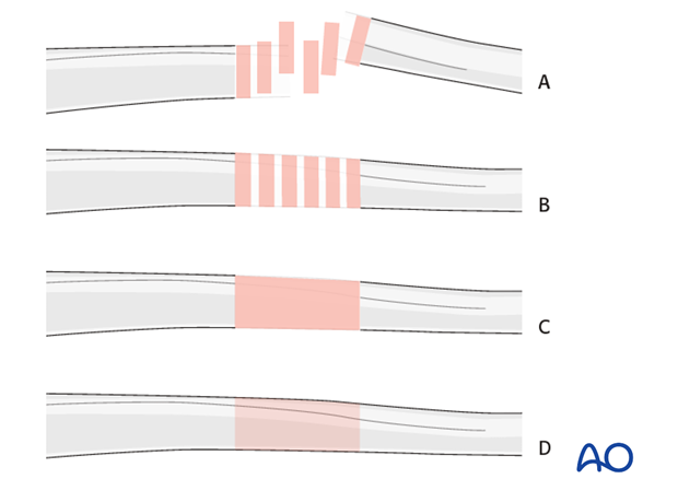
Throughout this treatment option illustrations of generic fracture patterns are shown, as four different types:
A) Unreduced fractureB) Reduced fracture
C) Fracture reduced and fixed provisionally
D) Fracture fixed definitively
Interlocking
Different nailing systems allow static or dynamic locking, with screws being inserted in various planes and directions.
Static interlocking with two screws on each side of the fracture is recommended.

2. Patient preparation and approach
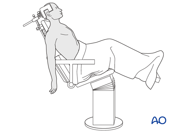
Patient positioning
For antegrade nailing, the beach chair is the preferred position.
If no beach chair is available, a supine position may be used.
Approach to entry point
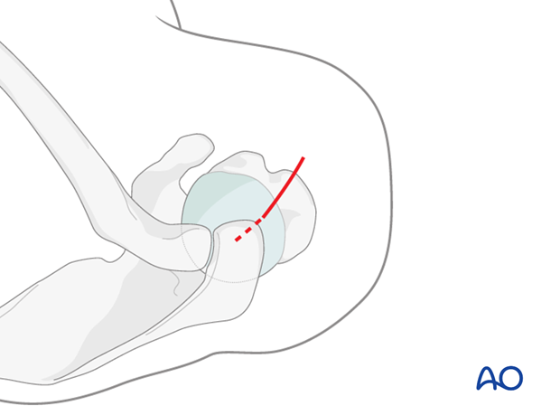
The entry point is accessed through an antegrade nailing approach.
3. Determining nail diameter and length
Nail diameter
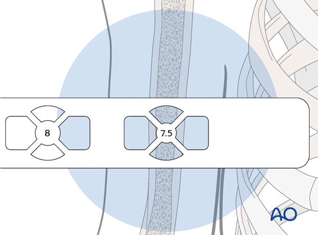
Place the radiographic ruler anteriorly on the upper arm over the medullary canal.
Visualize the medullary canal under image intensification in AP view and compare with the diameters of the marks on the ruler.
The correct diameter of the humeral nail corresponds to the diameter of the mark that fits completely into the medullary canal. Look carefully at the distal humeral canal. It may be narrower than the rest. If the isthmus is very narrow, consider reaming to allow the insertion of a larger diameter nail.
In our example, a nail of 7.5 mm diameter is chosen.
The diameter of the medullary cavity can also be measured on digital radiographs of the humerus. Take care to estimate the diameter at the narrowest site.
Nail length
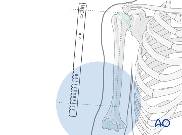
Provisionally reduce the fracture.
Place the ruler parallel to the arm, with the top-of-nail mark at the level of the anticipated insertion site in the humeral head.
Take an AP image intensifier view of the distal humerus together with the ruler.
The humeral nail should be as long as possible in the distal canal, consistent with its diameter. Determine this length with the aid of the ruler.
Keep in mind that the top of the nail should lie just below the surface of the bone.
The length of the nail can also be estimated by measurements of digital preop radiographs. Care should be taken that the whole humerus is pictured.
4. Entry point
Location of entry point
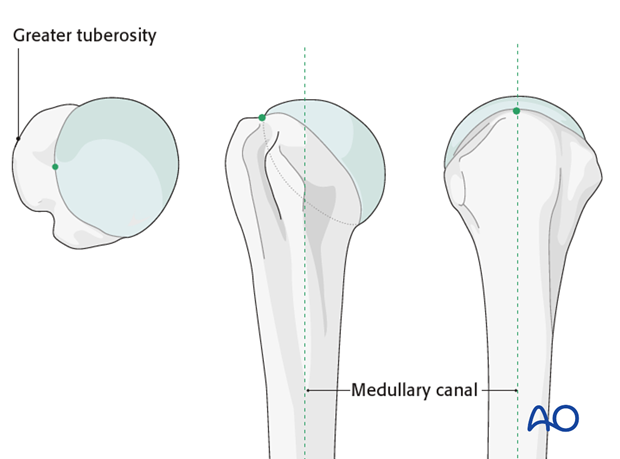
The correct entry point for the nail depends on its design. Straight nails have a more medial entry point compared to bent nails. Refer to the manufacturers' operative technique guides for further details.
The insertion point for the bent nail lies just at the lateral edge of the humeral articular cartilage.
Insertion of guide wire
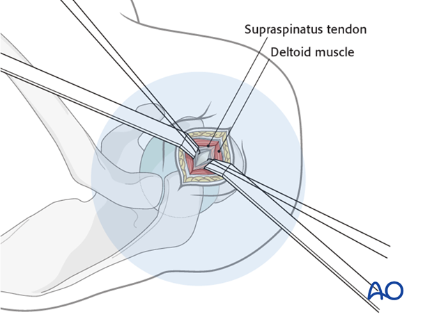
Insert a guide wire into the planned entry point, if necessary through a supraspinatus tendon split and confirm proper placement by image intensification.
Opening the canal
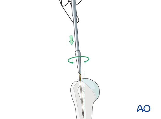
Open the proximal humerus with a cannulated awl, inserted over the guide wire.
5. Reaming
Indication
If the canal is very narrow rather than using a narrow nail, reaming will allow for the insertion of a larger diameter (so stronger) nail. This may be particularly useful when nailing a nonunion.
Procedure
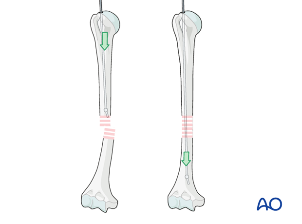
Pass an olive tipped guide wire across the fracture site. With experience it is possible to feel the olive tip of the wire working its way down the medullary canal, across the fracture and through the distal fragment. It is recommended that the proper passage is confirmed with image intensification.
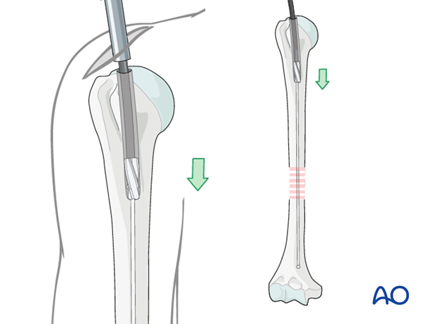
Ream up sequentially to an appropriate size for the desired nail. In segmental or multifragmentary fractures take care to avoid soft-tissue damage, particularly to the nerves and vessels, as the reamer is passed through the fracture zone.
Exchange the olive tipped wire to a straight guide wire, and then insert the nail over the guide wire. Alternatively, some nails may be introduced without a guide wire.
6. Nail insertion
Insertion handle
Mount the insertion handle/aiming guide on the proximal end of the nail using the connection screw.
Ensure that the convexity of the nail curvature points away from the insertion handle.

Nail insertion
Insert the nail with slightly rotating movements down to the fracture line.
Do not use a hammer, as this may increase the risk of fissure or fracture at the insertion site.
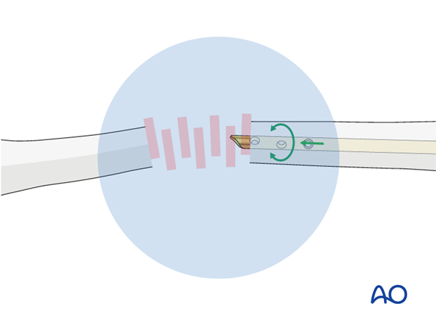
Advance the nail under image intensification just beyond the fracture site.
Reduction
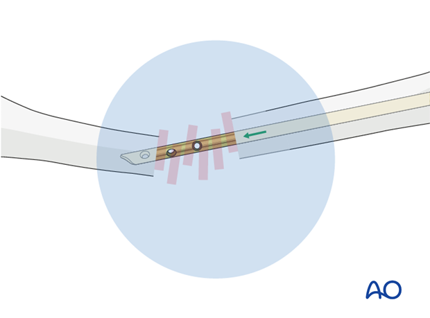
Pass the fracture zone under image intensification and make sure that the nail enters the distal fragment properly.
Use the nail tip as a reduction aid. In difficult cases, a guide wire may be helpful to help pass the nail through the fracture zone.
After passing the fracture site, adjust humeral shaft alignment, rotation, and length.
Confirm under image intensification in two different planes.
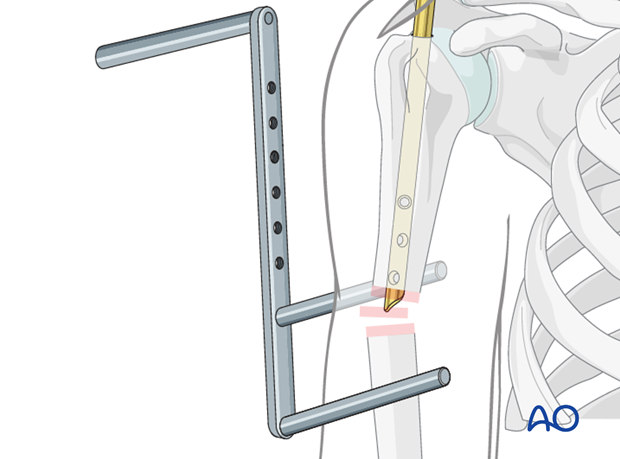
Pearl: F-tool for reduction
To lower the radiographic exposure to the surgeon’s hands use a radiolucent reduction tool (ie “F-tool”).
Open reduction
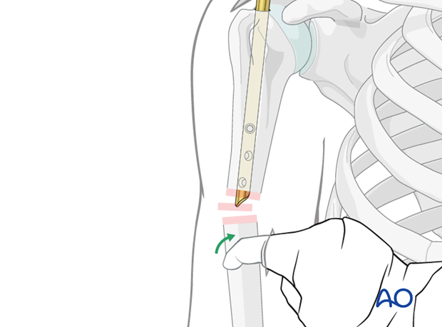
In some cases, it may be difficult to reduce the fracture and to pass the nail across the fracture site. One reason might be an interposition of soft tissues between the fragments.
If several attempts at introducing the nail into the distal fragment are unsuccessful the fracture site should be opened. Use a finger, bone hook or reduction clamp to reduce the fracture and pass the nail across the fracture site. This also reduces the radiographic exposure.
Be aware of the course of the radial nerve.
Definitive nail position
Gently advance the nail until it has reached the desired position just above the olecranon fossa. Avoid fracture distraction.
If a guide wire was used, remove it once the nail is in place.
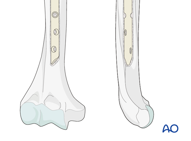
Make sure the proximal end of the nail is placed beneath the bony surface of the humeral head.
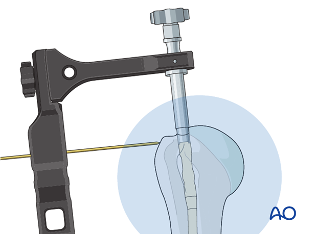
No protrusion of the nail may be tolerated. Confirm with appropriately oriented C-arm images that the top of the nail is below the surface of the bone. A K-wire which is passed through the handle may serve as a guide to estimate the proximal end of the nail.
If retrograde compression is planned insert the top of the nail into the humeral head far enough for it to remain below the articular surface after fracture reduction. See below for more details.
Confirm the correct rotation of the nail. Obtain a perpendicular AP view of the humeral head. Doing so, the handle has to be placed on the lateral side of the greater tuberosity. Be aware, that in this position, the forearm should point externally by approximately 25°.
Longitudinal reduction
Confirm reduction of the fracture under image intensification. Take care that there is no fracture gap as this has a high risk of nonunion.
If there is a gap, it may be possible to close it with manual compression along the axis of the humerus, telescoping the distal fragment over the nail.
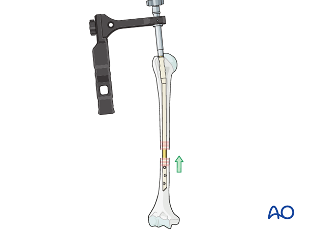
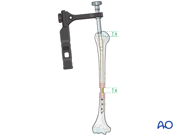
Alternatively, the gap can be closed with retrograde pulling of the nail after initial distal locking or by use of a compression mechanism implemented in the nailing system.
Both these techniques require the nail to be inserted deeper into the proximal fragment, so that as the fracture gap is closed the top of the nail comes to lie in the correct position. Otherwise an intraarticular, proximal protrusion of the nail will cause injury to the rotator cuff and impingement.
7. Proximal interlocking
Proximal dynamic interlocking
Place the trocar for the planned screw fixation through the aiming device, if necessary through a separate skin incision. Perform blunt dissection down to the bone so that the trocar may be placed without interposition of soft tissue.
Drill the hole for the dynamic interlocking screw, taking care that the tip of the drill does not penetrate the joint surface of the humeral head.
Measure the depth of the hole. The ideal length of the screw is 5 mm shorter than the measured length.
Finally, insert the interlocking screw and check for the correct position and length under image intensification in two planes.
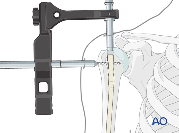
Proximal static interlocking
Insert the screw through the static interlocking hole in the same way as described for dynamic interlocking.
Take care that the tip of the drill does not penetrate the joint surface of the humeral head. If situated distal to the articular surface, the tip of the drill bit may penetrate the opposite cortex.
In some systems, as an alternative to double interlocking, one single proximal oblique static interlocking screw may be used.

8. Distal interlocking
Preliminary considerations
Correct any fracture distraction and/or malrotation before distal interlocking.
Typically, the distal interlocking is performed using a freehand technique.
The insertion of two interlocking screws is recommended.
The direction of the distal locking screws is determined by the particular nail being used. Insertion of interlocking screws from lateral to medial should be performed with care to avoid damage to the radial and/or ulnar nerve.
The placement of anterior-posterior screws only is shown here.
Skin incision
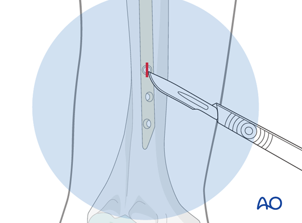
Use the image intensifier and adjust the x-ray plane to the intended locking hole. To do so, manipulate the C-arm and do not rotate the upper extremity. Moving the forearm may result in a rotational malalignment. The locking hole should appear as a perfect circle.
Make a sharp skin incision over this circle.
Soft-tissue dissection
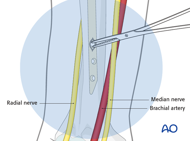
Use small scissors or artery forceps to prepare a track for insertion of the drill bit.
Blunt dissection of the soft tissues will prevent damage to the median nerve and brachial artery, located medial to the skin incision.
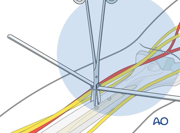
Pearl: use small retractors
Small right-angle retractors assure protection of muscular, vascular and neurological structures. Make sure that you can see the bone before drilling.
Please note that the retractors may interfere with the view under image intensification.
Drilling
Perform the positioning of the drill tip, its fine adjustment, and the drilling procedure under image intensification.
Many surgeons prefer a radiolucent drill attachment if it is available.
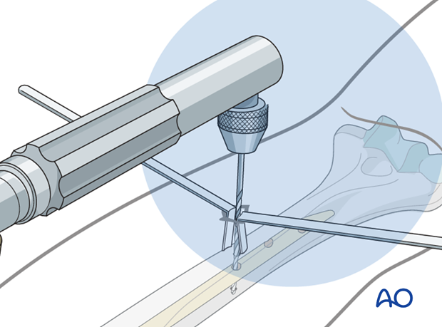
Center the radiopaque circles of the radiolucent drill on the locking hole.
Measure the length of the required screw with a depth gauge.
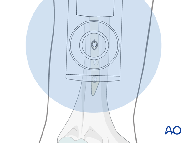
Insertion of interlocking screws
Insert the first interlocking screw and check for the correct position and length under image intensification in two planes.
Insert a second interlocking screw as described above.
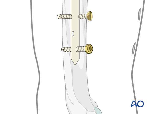
Pearl: absorbable suture around screw
To avoid losing the screw in the soft tissues during insertion and tightening, fasten an absorbable suture around the screw’s head beforehand.
This will help to retrieve a lost screw.

Final remark
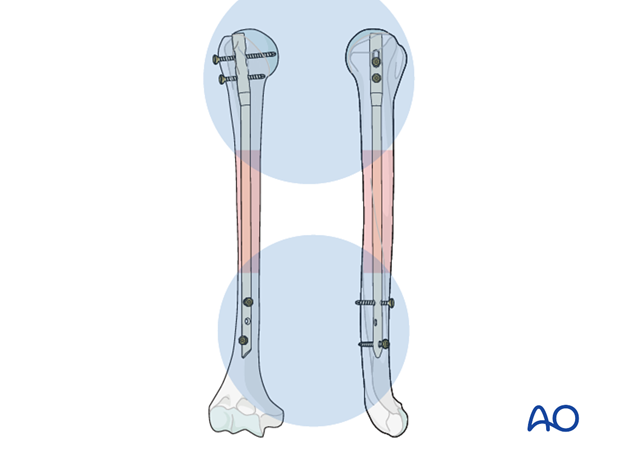
When interlocking is completed, check the definitive position of the implant under image intensification in two planes.
Take particular notice of the position of the proximal end of the nail and the location and length of all interlocking screws.
9. Option: fracture reduction/compression after distal locking
Distal interlocking
Insert the distal interlocking screws first as described above, ensuring that the top of the nail is sufficiently buried in the humeral head.
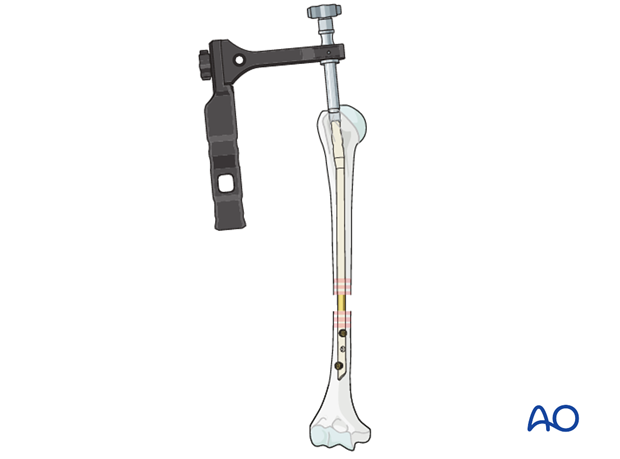
Manual reduction
Attach the removal device. Reduce the distal humeral fragment with gentle hammer blows, bringing the nail proximally within the proximal fragment. Confirm satisfactory reduction with image intensifier.
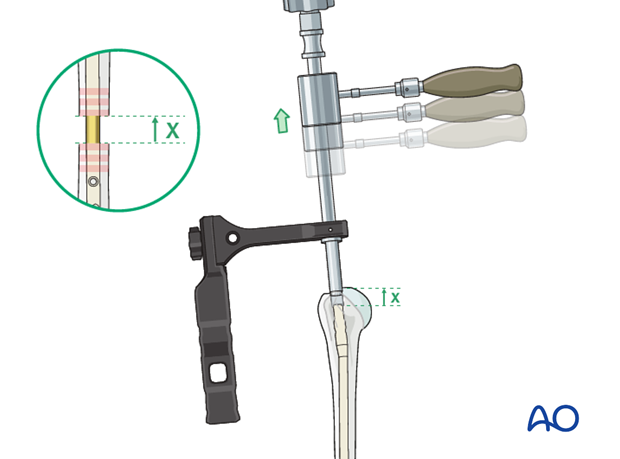
Reduction with compression device
Prior to compression insert the proximal dynamic interlocking screw as described above.
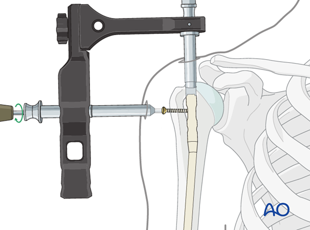
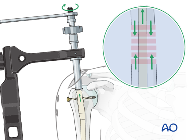
Compression of the fracture site or closure of a gap is applied by inserting a compression screw from the top of the nail. By tightening the screw, the whole nail with the distal fragment is pulled retrogradely.
Confirm the effect under image intensification.
After achieving satisfactory reduction secure the reduction by inserting the static interlocking screw.
Remove the compression screw.
10. Nail capping
Remove the insertion handle/aiming guide and its connecting screw.
Insert an end cap, to prevent ingrowth of bony tissue.
End caps of different lengths may be available. The top of the end cap should lie just below the articular cartilage, to facilitate later implant removal, but must not protrude above the humeral surface.
Confirm the proper size and position of the end cap under image intensification.
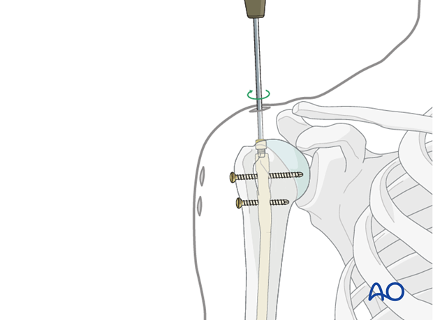
Pearl: using the 0 mm end cap
In some systems a 0 mm end cap, which fits completely within the nail, may be inserted through the insertion handle. To do this, the connection screw needs to be removed carefully without moving the insertion handle. The end cap can then be passed through the channel of the insertion handle. This is not possible for longer end caps as they have a larger diameter.
