ORIF - Bridge plating (blade plate)
1. Principles
This implant is especially useful in nonunion surgery around the sub trochanteric region. It can be used in acute situations, but other implants are simpler to use.
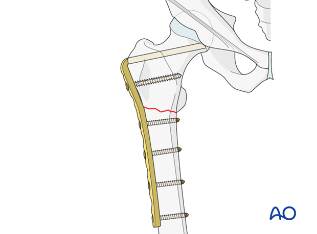
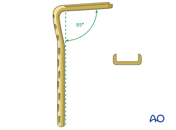
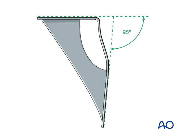
Angled blade plates have a blade with a "U" profile and a fixed angle between the blade and the plate.
In the proximal femur, the blade needs to be inserted in the middle of the femoral neck and at a predetermined angle to the shaft axis. In addition, the plate portion of the angled blade plate must line up with the axis of the femoral shaft at the end of the procedure.
Because of these technical complexities, a preoperative plan and tactic, including a preoperative drawing, are essential, so that the operation can be conducted step by step. The surgeon must be precise and pay particular attention to anatomical landmarks, the siting and orientation of the angled blade plate, in both AP and axial views, as well as rotation of the blade about its axis (which determines the alignment of the plate with the femoral shaft).
2. Implant and instrumentation
Implant
The two round holes next to the blade accept 6.5 mm cancellous bone screws; the remaining screw holes have a DCP profile and accept 4.5mm. cortical screws. The blades come in lengths of 50, 60, 70 and 80 mm. The 70 mm blade is the one most commonly used in the adult proximal femur.
There are 7, 9 and 12-hole versions of the 95° angled blade plates.
Instrumentation
Several dedicated instruments are needed for the precise conduct of the angled blade plate insertion, in accordance with the preoperative plan. No fluoroscopy can substitute for a three-dimensional appreciation of the local anatomy, nor will it serve as a guide to the correct insertion of the guide wires.
Correct insertion is based on certain anatomical landmarks and on the geometry of the 95º angled blade plate. The image intensifier is used to check the position of the definitive guide wire and the final position of the seating chisel.
Seating chisel
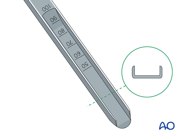
The seating chisel is used for cutting the track for the blade in the proximal femur.
It has a “U” profile that corresponds to the profile of the blade of the angled blade plate.
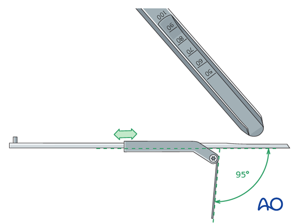
The seating chisel guide that slides over the seating chisel, is used to determine the rotation of the seating chisel about its long axis.
The flap of the seating chisel guide must remain in line with the long axis of the femoral shaft throughout chisel insertion.
Condylar blade guide
The angle between the flap and the body of the seating chisel guide may be set with the aid of the 85° condylar blade guide and is maintained by tightening the screw with a screwdriver.
Slotted hammer
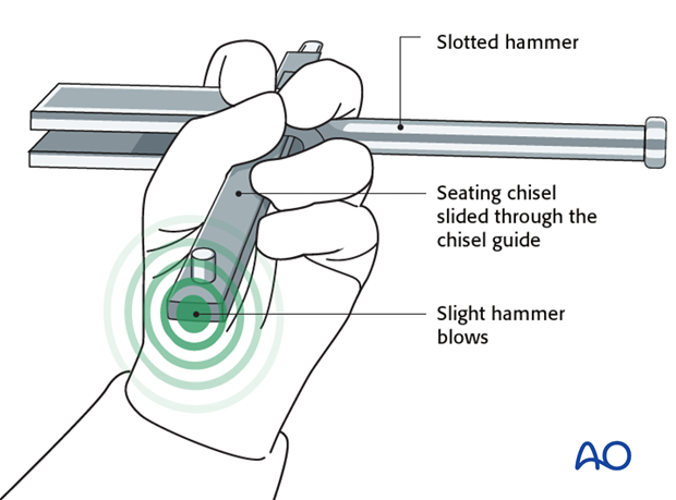
During insertion, the rotation of the seating chisel is controlled with the slotted hammer. The slotted hammer serves also for removal of the seating chisel, or for hammering out the plate holder when removing a blade plate.
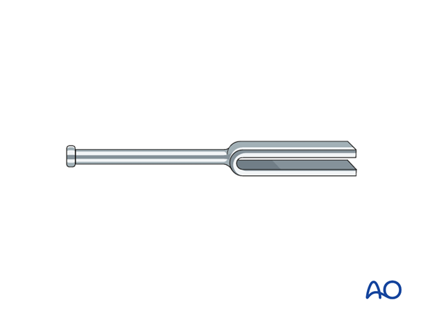
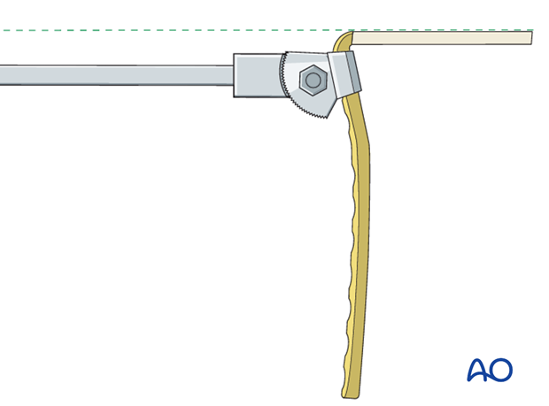
Plate holder / introducer
The plate holder/introducer is used for insertion and removal of blade plates. The blade plate should be so fastened in the plate holder that its long handle is in line with the blade of the angled plate.
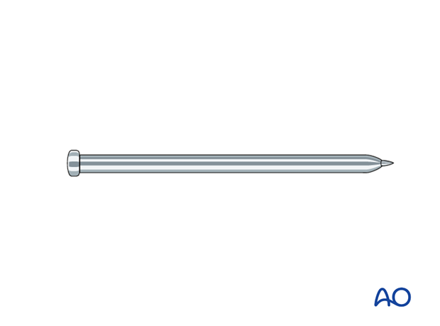
Impactor
The impactor is used to drive the last 5 mm of the blade into the bone.
3. Preoperative planning
Ideal position of the 95° angled blade plate within the proximal femur
The trabecular anatomy and distribution of bone in the proximal femur determines the optimal position for the blade of the 95º angled blade plate. There is a zone within the head where the tension and compression trabeculae intersect. This is the zone offering good anchorage for the tip of the blade. The tip of the blade should come to lie just below this point of trabecular intersection on the AP image and in the center of the neck on the axial view. The blade of the 95º angled blade plate should pass approximately 10 mm below the superior cortex of the neck.
Note that the tip of the blade lies in the lower half of the femoral head. The blade passes below the superior cortex of the neck.
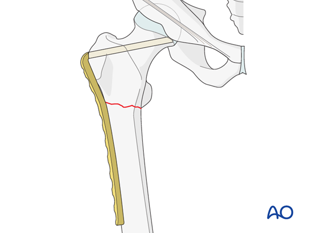
Drawing the plan
X-rays of the uninjured femur are taken to serve as a template for preoperative planning. The x-rays are taken with the hip in 15°- 20° internal rotation to correct for femoral neck anteversion.
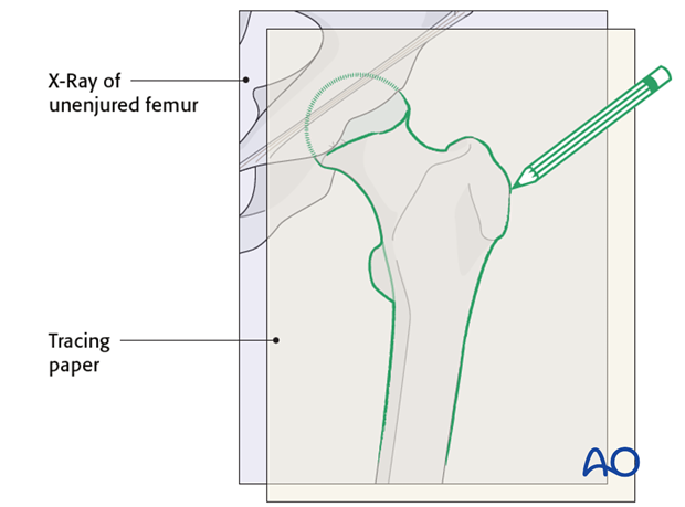
A tracing of the outline of the uninjured proximal femur is then reversed and the fracture lines are added.
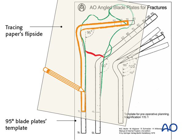
The appropriate angled blade plate is then chosen, using the transparent implant templates and traced onto the plan.
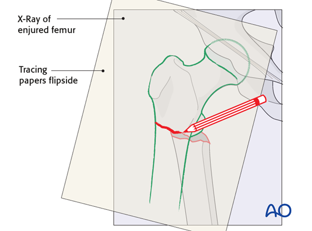
The appropriate angled blade plate is then chosen, using the transparent implant templates underlying the tracing. The outline of the chosen implant is then added to the tracing.
To assist in the choice of the insertion point for the seating chisel, measure the distance from the tip of the greater trochanter to the center of the insertion point. This measurement can be used intraoperatively to locate the insertion point.
A step-by-step tactic is then derived from this drawing and should stipulate the order in which the various steps of the procedure will be performed. It should also indicate whether a gliding hole for an interfragmentary lag screw is to be predrilled prior to fracture reduction, depending on the inclination of the fracture plane.
These technical drawings and their derived tactic are mandatory for any angled blade plate procedure.
4. Patient preparation
The patient may be placed in one of the following positions:
5. Approach
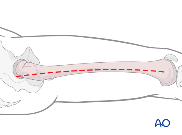
For this procedure a lateral approach is used.
6. Preparing the blade channel
Correct track for the angled blade plate
Before an angled blade plate can be inserted into bone, a channel must be cut with the U-profile seating chisel. The sides of the tip of the seating chisel converge slightly, which facilitates the centering of the chisel within the femoral neck.
To insert the 95º angled blade plate correctly into bone, 4 degrees of freedom must be controlled:
- the point of entry of the blade into bone,
- parallelism to the anteversion of the femoral neck,
- the angle between the blade and the femoral shaft axis and
- the rotation of the seating chisel about its long axis.
Once the track of the blade is determined on the preoperative plan, the surgeon will know the exact position that the seating chisel should occupy in the bone.
Parallelism to the anteversion of the femoral neck and the angle between the blade and the femoral shaft axis
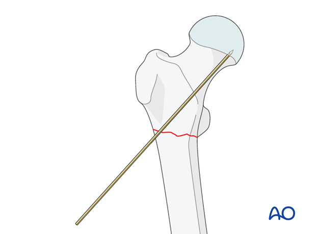
Guide wires are used to mark the plane of anteversion of the femoral neck and also to mark the appropriate inclination of the seating chisel in relation to the long axis of the femur. The surgeon will be guided in the chisel insertion by a definitive guide wire.
Firstly, a wire is passed in close contact with the front of the femoral neck and will indicate the axis of the neck in the axial plane. This wire must pass distal to the anterior ridge which runs along the front in the intertrochanteric area, or it may be deflected anteriorly.
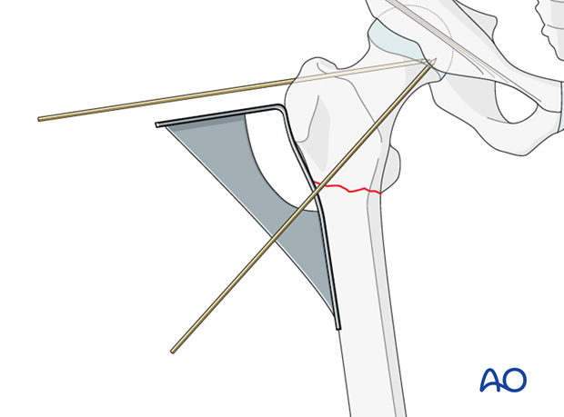
The 95º condylar plate guide is then placed along the lateral cortex and a second, definitive guide wire is inserted, parallel in the axial view to the first guide wire and parallel with the upper edge of the condylar plate guide in the AP view. It is drilled into the greater trochanter just above the planned point of entry. The track for the seating chisel will be parallel to this wire. The wire’s position should be checked radiologically in both planes, and adjusted accordingly, as necessary.
Preparing the point of entry
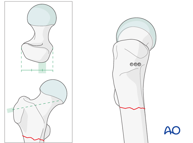
Guided by the measurement made on the preoperative plan, the point of entry on the outer face of the greater trochanter is determined.
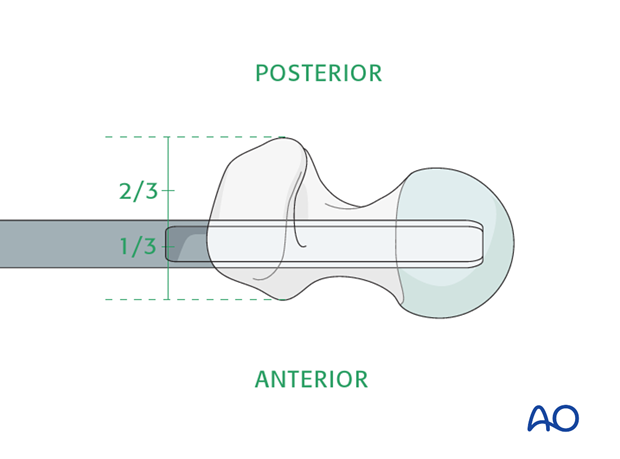
It is important to remember that, at this level, the posterior edge of the greater trochanter overhangs more than the anterior edge and the center of the point of insertion is at the junction of the anterior one third and middle one third of the outer face of the greater trochanter.
Three 4.5 mm drill holes are made as illustrated.
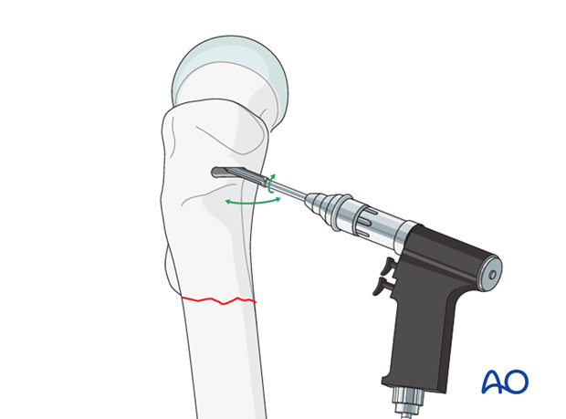
These holes are then enlarged with a router to produce a horizontal slot matching the width and height of the seating chisel.
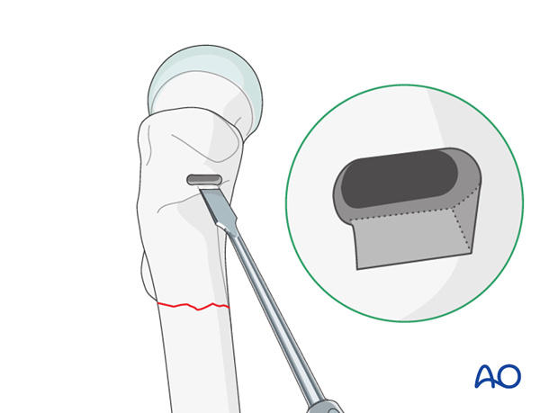
The lower edge of the entry hole should be beveled, using a chisel, to accommodate the curve of the shoulder of the angled blade plate.
Preparation of the track for the blade
The seating chisel can now be inserted through the prepared entry slot and parallel in both axial and AP views to the definitive guide wire. This parallelism is judged by frequent visual reference, in both planes, to the advancing seating chisel and the guide wire. Radiology has no part to play in this maneuver. The use of the slotted hammer over the seating chisel aids the control of this track.
Throughout the insertion of the seating chisel, the parallelism of the tongue of the seating chisel guide to the femoral shaft axis is also carefully maintained.
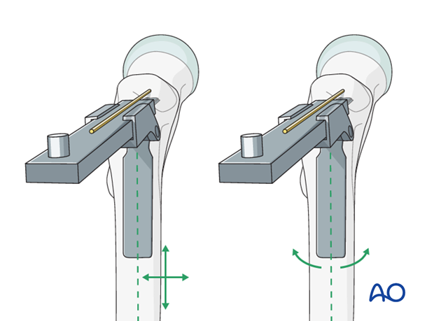
This is the most demanding and crucial step of the procedure, and the grip on the slotted hammer and the seating chisel guide, as drawn, is crucial.
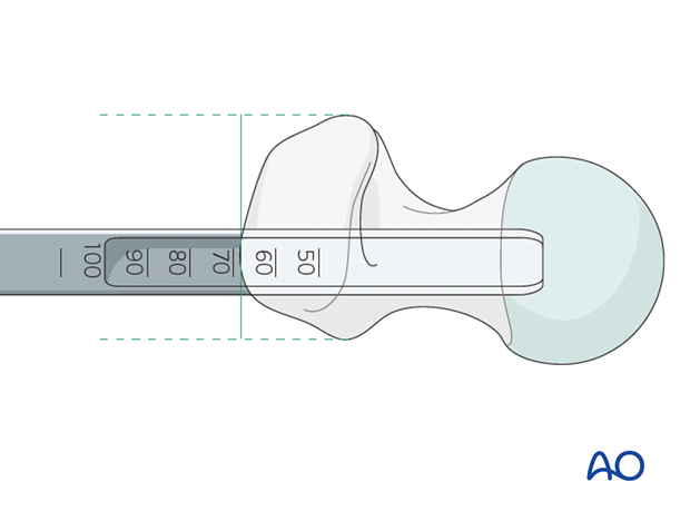
Seating chisel insertion depth
Once the seating chisel has been inserted, its position should be checked radiologically. This determines also whether the planned blade length is appropriate. The seating chisel bears markings that indicate the depth of its insertion.
The seating chisel is then removed by back strokes with the slotted hammer.
7. Plate insertion
Blade insertion
The chosen 95° angled blade plate is then mounted into the plate holder and the blade is pushed by hand into the pre-chiseled track. The blade should pass easily into the precut track and light blows with a hammer should be all that is required to insert it into the femoral neck.
When the plate is about 5 mm from the bone, remove the plate holder and hammer the plate fully home, using the point of the impactor in the indent on the shoulder of the implant.

Proximal screw insertion
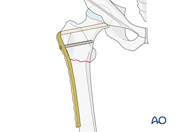
The blade should be stabilized with a screw. After the angled blade plate has been inserted into the proximal femur, it is secured with a fully threaded 6.5 mm cancellous screw through the most proximal of the holes of the plate.
The use of a cortical screw at this site would require drilling of the calcar of the femur, with the attendant weakening of this important bony buttress.
8. Reduction and compression of fracture
Fracture compression
Once the angled blade plate is firmly anchored in the proximal fragment, the distal femur is aligned onto the plate and held, if necessary, with a clamp.
In single plane transverse or short oblique fractures, the first screw in the distal fragment should be a load screw, to compress the fracture.
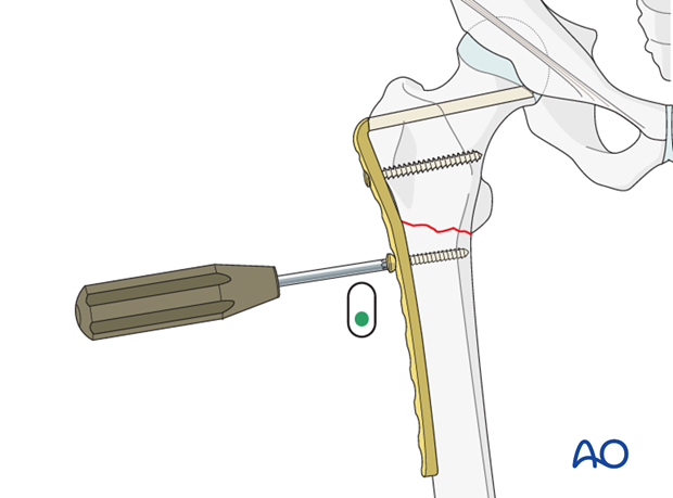
Completion of the fixation
The remaining, neutral screws are then inserted: at least 8 cortical holds are necessary in the shaft fragment.

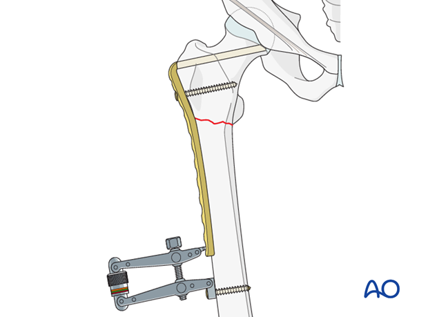
Pearl: articulated tension device
In nonunion, sufficient compression may only be achieved using an external compression device.
9. Aftercare
Compartment syndrome and nerve injury
Close monitoring of the femoral muscle compartments should be carried out especially during the first 48 hours, in order to rule out compartment syndrome.
Postoperative assessment
In all cases in which radiological control has not been used during the procedure, a check x-ray to determine the correct placement of the implant and fracture reduction should be taken within 24 hours.
Functional treatment
Unless there are other injuries or complications, mobilization may be started on postoperative day 1. Static quadriceps exercises with passive range of motion of the knee should be encouraged. If a continuous passive motion device is used, this must be discontinued at regular intervals for the essential static muscle exercises. Afterwards special emphasis should be placed on active knee and hip movement.
Weight bearing
Full weight bearing may be performed with crutches or a walker.
Follow-up
Wound healing should be assessed regularly within the first two weeks. Subsequently a 6 and 12 week clinical and radiological follow-up is usually made. A longer period may be required if the fracture healing is delayed.
Implant removal
Implant removal is not mandatory and should be discussed with the patient, if there are implant-related symptoms after consolidated fracture healing.
