Compression plate application to transverse fractures
Function
The plate produces compression at the fracture site to provide absolute stability.
Application (transverse fractures)
ReductionIf possible, the fracture is reduced and temporarily fixed with forceps. Place the forceps so they will not interfere with the planned plate position.
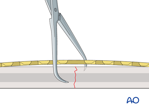
If the plate is exactly contoured to the anatomically reduced fracture surface, there will be some gapping of the far cortex when the plate is tensioned by tightening the load screw.
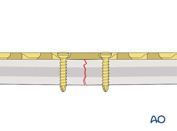
This 3D model shows a screw inserted in compression mode with an unbent plate.
When a transverse fracture is compressed with a plate that is not overbent but exactly pre-contoured to the reduced fracture surface (bottom panel), compression will first be exerted at the cortex under the plate (near cortex). The cortex opposite the plate (far cortex) will open resulting in a fracture gap. This may lead to delayed union of the far cortex.
The solution to this problem is to “overbend” the plate so that its center stands off 1–2 mm from the anatomically reduced fracture surface.
The overbend should lie directly over the fracture line.
When the first screw is inserted, slight gapping of the cortex will occur directly underneath the plate. After fixation is complete, the plate will be in contact with the bone throughout its length, but will act as a spring, providing compression at the far cortex.
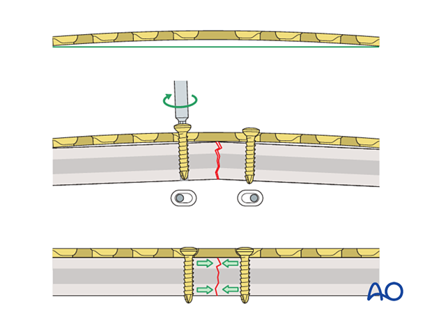
If the plate is overbent too much (bottom panel), compression will first be exerted at the far cortex and this causes a gap of the cortex under the plate (near cortex) when inserting the second screw eccentrically in compression mode. Such a gap should be avoided.
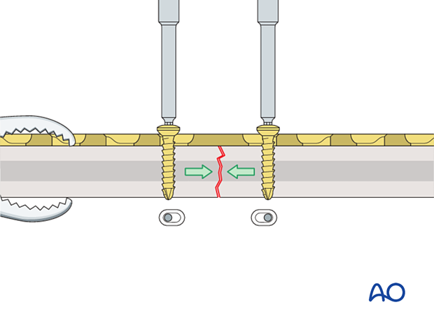
The prebent plate is fixed to one of the main fragments with a screw inserted in compression mode. Reduction forceps are placed on the opposite fragment to hold it in the reduced position against the plate. The screw is not fully tightened.
More information about screw insertion in compression mode is provided here.
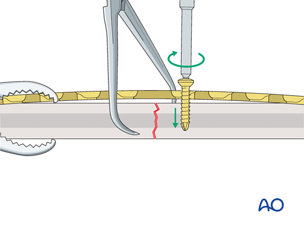
This 3D model shows screw insertion in compression mode with an overbent plate.
To compress both the near and opposite (far) cortices, the plate should be slightly overbent before application, resulting in a convex shape, so there is a small gap between plate and bone at the fracture. Before the screws are inserted, the fracture is reduced. With the insertion of the first screw eccentrically in the screw hole, the overbent plate is pressed onto one bone fragment which causes slight displacement of the reduced fracture. The displaced fragment will be relocated with the insertion of the second screw in compression mode.
A screw is inserted in compression mode in the opposite fragment. To maintain reduction, it is recommended to tighten the screws gradually by alternating between the two sides.
These 3D models show that locking head screws cannot be used for compression. The bottom panel shows that locking head screws cannot be inserted eccentrically in compression mode, unlike conventional screws (top panel).
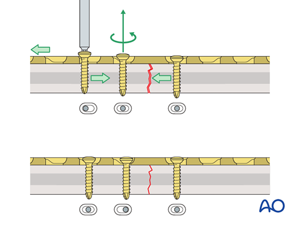
If a fracture gap remains after insertion of the two compression screws, a third screw can be inserted in compression mode. This can be located on either side of the fracture. Before this screw is tightened, the compression screw already placed in the same fragment needs to be loosened. Once the third screw is fully tightened, the loosened screw is re-tightened. Additional screws are then inserted in neutral mode.
Application of dynamic compression plate to transverse fractures.


