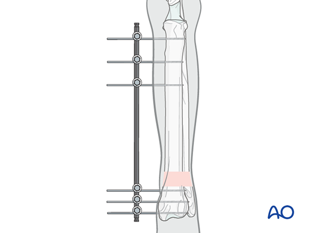
General considerations on external skeletal fixators
1. Advantages of external skeletal fixation
- Less damage to the periosteal blood supply to the bone
- Minimal interference with soft tissue in the distal limb when placed through safe corridors
- Helpful in stabilizing grade 3 open fractures
- Easy removal or staged disassembly
- Easily facilitates modulation of fracture healing
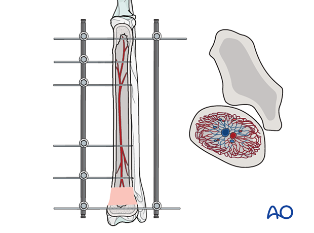
2. Disadvantages of external skeletal fixation
- Time-demanding aftercare
- Requires patient and owner cooperation
- Risk of wound complications, especially pin tract infection
- Pin-bone interface loosening is common after 8 weeks
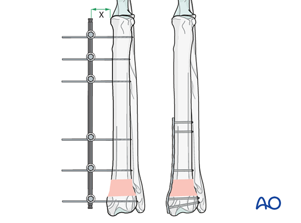
3. External skeletal fixator types and configuration
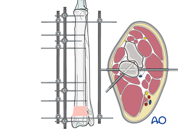
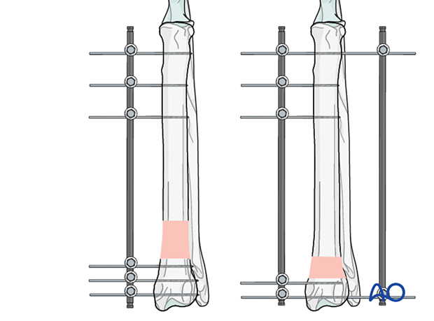
Type IA: uniplanar and unilateral external skeletal fixator (ESF)
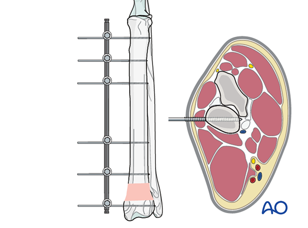
Type IB: biplanar, unilateral
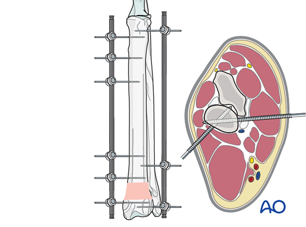
Type II: uniplanar bilateral external skeletal fixator
The connecting bars are placed parallel to the bone’s long axis.
Full pins are placed across the radius. In the most proximal region of the radius, care should be taken to minimize trauma to the extensor and flexor muscles.
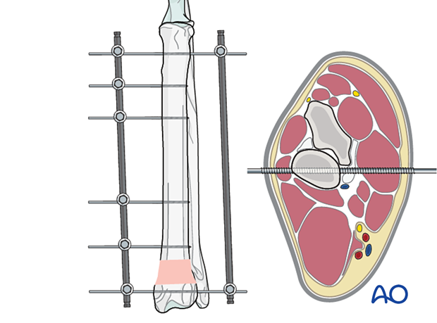
Type III: biplanar, bilateral external skeletal fixator
Full pins are placed across the radius. In the most proximal region of the radius, care should be taken to minimize trauma to the extensor and flexor muscles.
Depending upon the specific system utilized, type III frames might be excessively rigid, leading to delays in fracture healing. Type III frames have greater pin tract morbidity and are more cumbersome and time-consuming to place and maintain. With improved modern systems, application protocols, and postoperative management strategies, type III frames are rarely necessary.
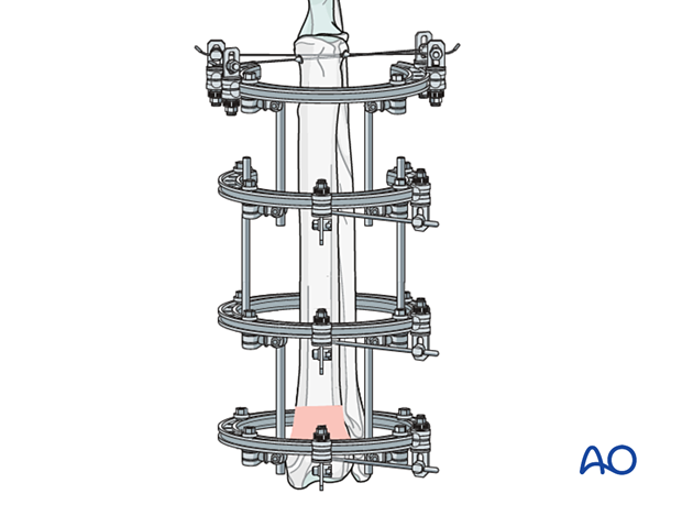
Circular external skeletal fixators use wires rather than pins to stabilize bone fragments. The wires are connected to the circular frame and the stiffness can be increased by tightening the wire. The overall stiffness of the construct can be increased by connecting the circular (ring) elements together.
4. Biomechanical aspects
The ESF should provide enough stability to maintain reduction. The surgeon has to understand the biomechanical principles to correctly apply the device to achieve adequate stability. Ideally, at least three pins have to be inserted into each main fragment through the safe zones.
The pins should be evenly distributed in each main fragment.
If the distal segment is too short to allow placement of three half-pins, then one full pin and one half-pin (ideally orthogonal/near orthogonal to the full pin) may suffice to provide sufficient rigidity for healing. Alternatively, a ring may be connected to a linear ESF to create a hybrid ESF.
The stiffness of the frame depends upon the following factors:
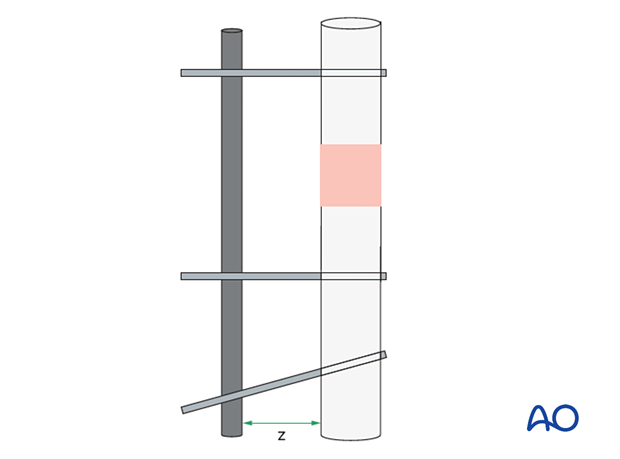
- Even distribution of the pins in each main fragment with the pin closest to the fracture line but no closer than one bone diameter
- Distance of the connecting bar from the bone (z): the closer, the stiffer (should generally not be closer than 0.5 cm from the skin edge)
- Number of pins: stiffness increases up to four pins per segment
- Number of bars: two are stiffer than one (but, with modern systems, are generally unnecessary biomechanically)
- Composition of the bars. Modern materials, such as carbon fiber and titanium, offer greater strength per weight when compared to stainless steel
- Frame configuration: stiffness (within a manufacturer’s system) is for type III > type II > type IB > type IA
- Clamp design: some clamps have less loosening than others
- Combination of limited internal fixation (lag screw) with external fixation; only rarely indicated because mixing an elastic with a stable fixation technique is not recommended
- Pin design and size: positive profile or, preferably, negative profile tapered runout pins are indicated. Pin diameter should be approximately 25% of the bone diameter at the intended pin site. Full pins are stronger than half-pins.
5. Application principles
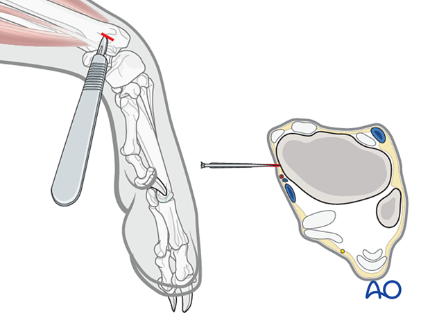
Releasing incisions
Pins should be placed through large releasing incisions. Incisions should be made parallel to the long axis of the bone. The soft tissue should be bluntly separated with a hemostat to the bone.
Pilot hole
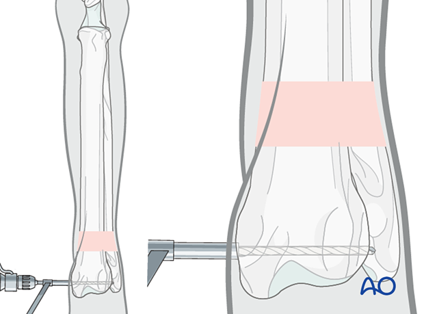
The pins should always be placed through a pilot hole. The diameter of the hole is determined by the size and design of the pin.
The pilot holes are generally drilled parallel to adjacent joint surfaces/perpendicular to the long axis of the bone.
A drill guide should be used to protect the adjacent soft tissues during drilling.
Pin insertion
The threaded pin should be placed in the pilot hole with a surgical drill. In this scenario, the heat generated by pin insertion does not exceed the threshold for thermal necrosis of the adjacent bone. Therefore, the pin insertion rate is guided by the thread pitch of the pin.
The pin should be inserted so that the threaded full circumference of the pin engages the entire trans-cortex. If the pin is inserted too deep, it can be retracted to the proper position with minimal loss of pin-bone interface as long as the smooth portion of the pin does not violate the cis-cortex.
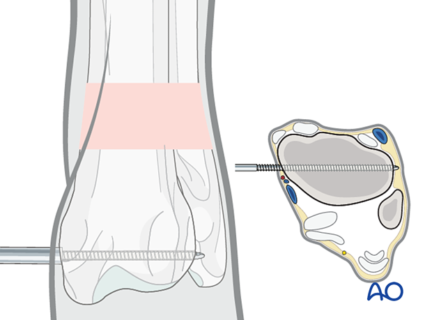
Order of pin insertion
The first pins to be inserted are the ones adjacent to the joints.
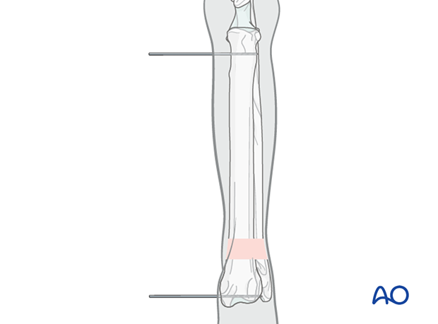
Connecting bar
After placing the most proximal and distal pins, a connecting bar with all anticipated clamps should be attached to the proximal and distal pins.
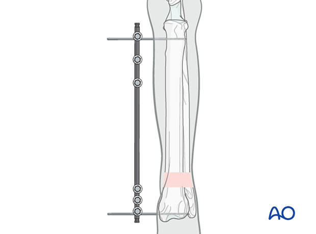
The remaining pins are placed by drilling the pilot hole with a drill guide placed through the clamp. Pins closest to the fracture line are placed first, followed by pins in the remaining bone between the peripheral and central pins.
After the final hole is drilled, the drill guide is removed, and the pins are placed through the clamps on the connecting bars.
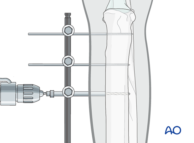
After the final hole is drilled, the drill guide is removed and the pins are placed through the clamps on the connecting bars.