Plating principles
1. Introduction
Plating modalities
Plates may be applied in various modes according to the function required. These include:
- Neutralization (protection)
- Compression
- Bridging
- Buttress (antiglide)
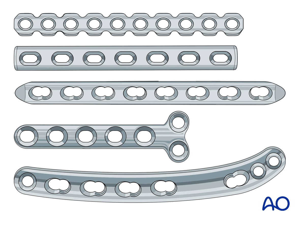
Plate designs
Various plate designs are available. These may be larger or smaller, thicker or thinner, as appropriate to various anatomic sites and the loads to which they will be subjected.
The holes in the plate may be designed for locking screws, non-locking screws, or a “combi hole” that can accommodate locking or non-locking screws. Additionally, the holes may offer the option of dynamic compression.
Plates are designed to have reduced contact area on the bone (Iimited contact plates).
Reconstruction plates are designed to be easier to contour in complex anatomic locations.
These 3D models show the effect of different plate designs on bending stiffness.
Increased width is shown in the top panel, a normal plate is shown in the center panel, and increased thickness is shown in the bottom panel. Out of these, the thickness of the plate is the most influential parameter for bending strength.
Plate contouring
The plate must fit the shape of the bone.
Most bones show a flare towards the metaphysis, so plates applied in these regions usually need to be contoured.
The use of a flexible template can facilitate plate contouring.
Where locking screws are used, the bone-plate construct remains stable even if the plate is not in direct contact with the bone. Therefore, contouring does not need to be so accurate, yet needs to be within 1–2 mm of the bone surface.
Anatomic plates are available for some applications in dogs (eg, TPLO, distal femoral osteotomy, distal humerus). Be aware that plates are designed from data taken from a normally-distributed population of subjects, and they may need to be adjusted to fit individual patients.
2. Neutralization (protection) plates
Function
A plate neutralizes bending and rotational forces to protect a lag screw fixation.
This is equally true for plates with locking or non-locking screws.
Application
Reduce the fracture and stabilize it with one or more lag screws.
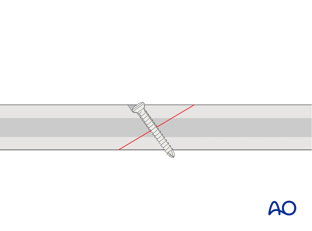
This 3D model shows application of a lag screw.
A lag screw placed perpendicular to the fracture plane is used to achieve optimal compression of fracture surfaces in a simple fracture. If precise orientation is not achievable, some degree of malalignment may be induced. Lag screws can provide useful compression to enhance fracture plane contact and hence healing, but the fracture plane is not stable when a bending or torsional force is applied. Resistance to bending or torsional forces is provided by a neutralization (protection) plate.
The appropriately contoured plate is applied to the bone, and screws inserted in a neutral mode.
Depending on plate design, bone quality, implant availability, and surgeon’s preference, fixed angle locking screws, variable angle locking screws, or non-locking screws may be inserted.
It is not necessary to fill every hole in the plate with screws, as long as enough screws are inserted to obtain sufficient hold and maintain the reduction until the fracture heals.
Care must be taken to ensure that the screws in the plate do not interfere with the lag screw.
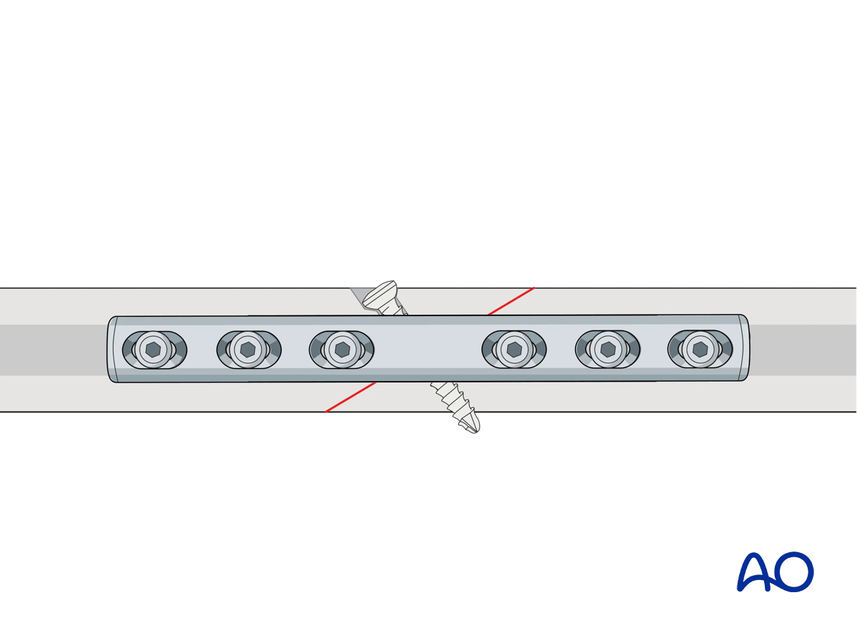
This 3D model shows a lag screw with a neutralization plate fixed in an orthogonal orientation to the screw.
By placing the neutralization plate in a plane rotated 90° to the plane of the lag screw, torsion and bending forces acting on the screw are reduced. The overall stability of the construct is increased.
3. Compression plates
Function
The plate produces compression at the fracture site to provide absolute stability.
Application (transverse fractures)
ReductionIf possible, the fracture is reduced and temporarily fixed with forceps. Place the forceps so they will not interfere with the planned plate position.
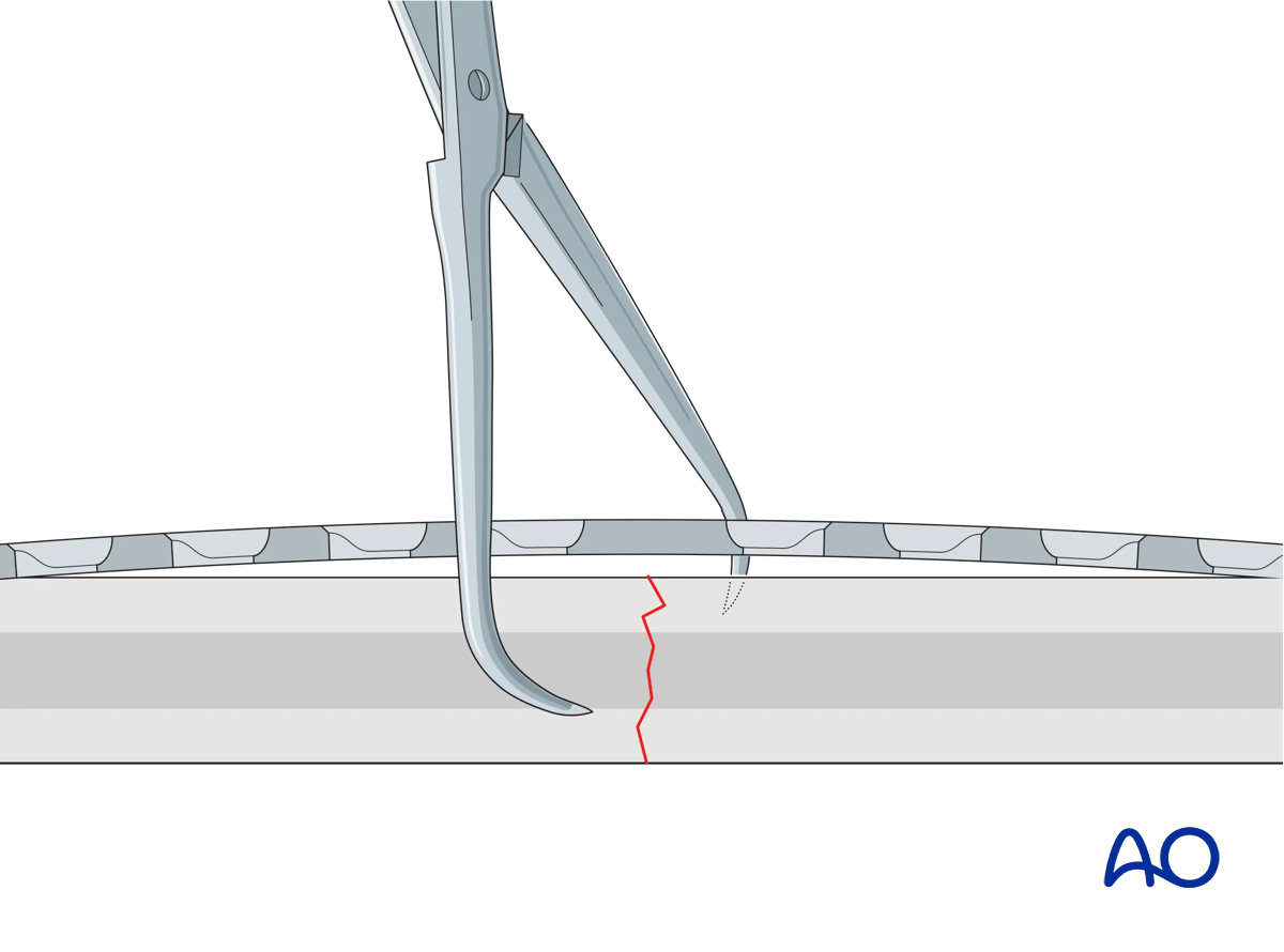
If the plate is exactly contoured to the anatomically reduced fracture surface, there will be some gapping of the far cortex when the plate is tensioned by tightening the load screw.
This 3D model shows a screw inserted in compression mode with an unbent plate.
When a transverse fracture is compressed with a plate that is not overbent but exactly pre-contoured to the reduced fracture surface (bottom panel), compression will first be exerted at the cortex under the plate (near cortex). The cortex opposite the plate (far cortex) will open resulting in a fracture gap. This may lead to delayed union of the far cortex.
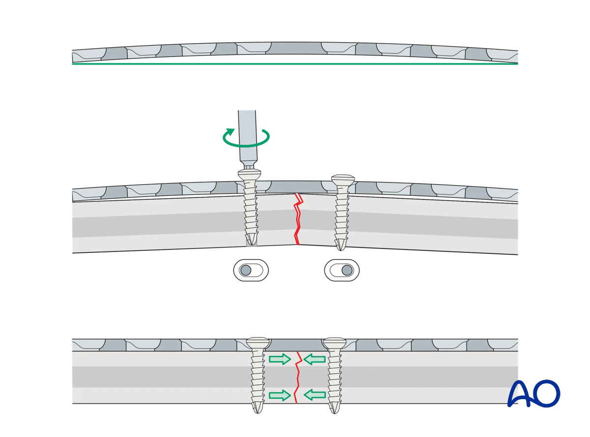
The solution to this problem is to “overbend” the plate so that its center stands off 1–2 mm from the anatomically reduced fracture surface.
The overbend should lie directly over the fracture line.
When the first screw is inserted, slight gapping of the cortex will occur directly underneath the plate. After fixation is complete, the plate will be in contact with the bone throughout its length, but will act as a spring, providing compression at the far cortex.
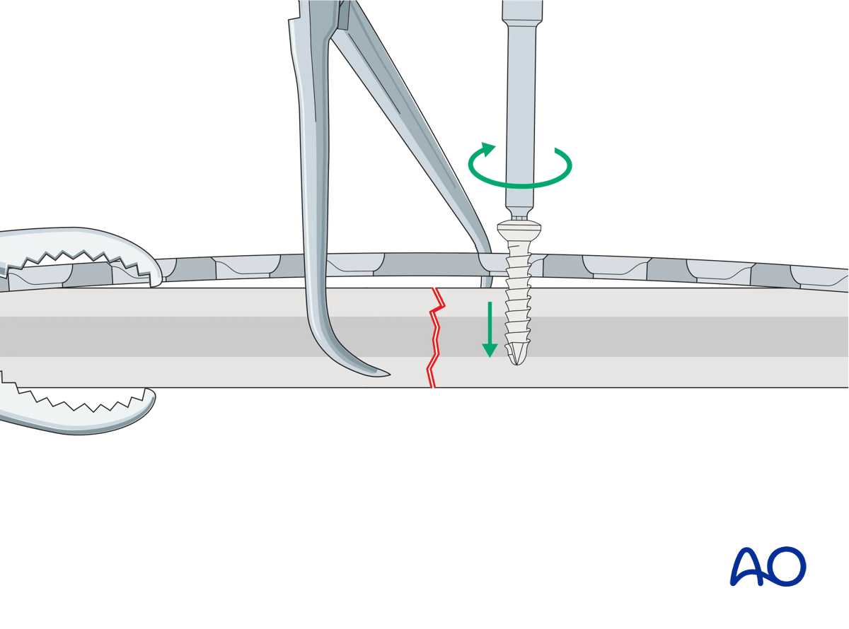
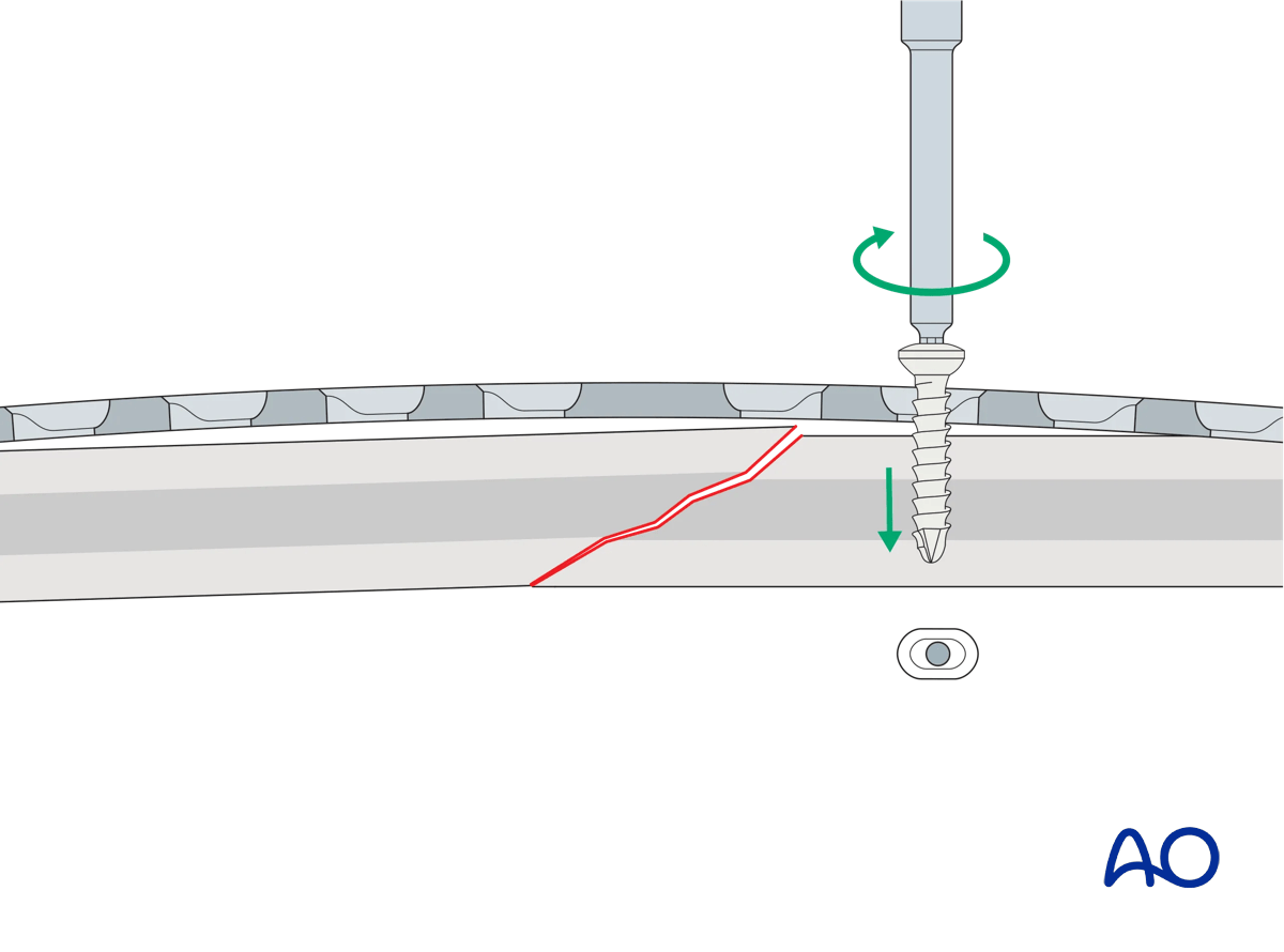
The prebent plate is fixed to one of the main fragments with a screw inserted in compression mode. Reduction forceps are placed on the opposite fragment to hold it in the reduced position against the plate. The screw is not fully tightened.
This 3D model shows screw insertion in compression mode with an overbent plate (Step 1).
To compress both the near and opposite (far) cortices, the plate should be slightly overbent before application, resulting in a convex shape, so there is a small gap between plate and bone at the fracture. Before the screws are inserted, the fracture is reduced. With the insertion of the first screw eccentrically in the screw hole, the overbent plate is pressed onto one bone fragment which causes slight displacement of the reduced fracture. The displaced fragment will be relocated with the insertion of the second screw in compression mode.
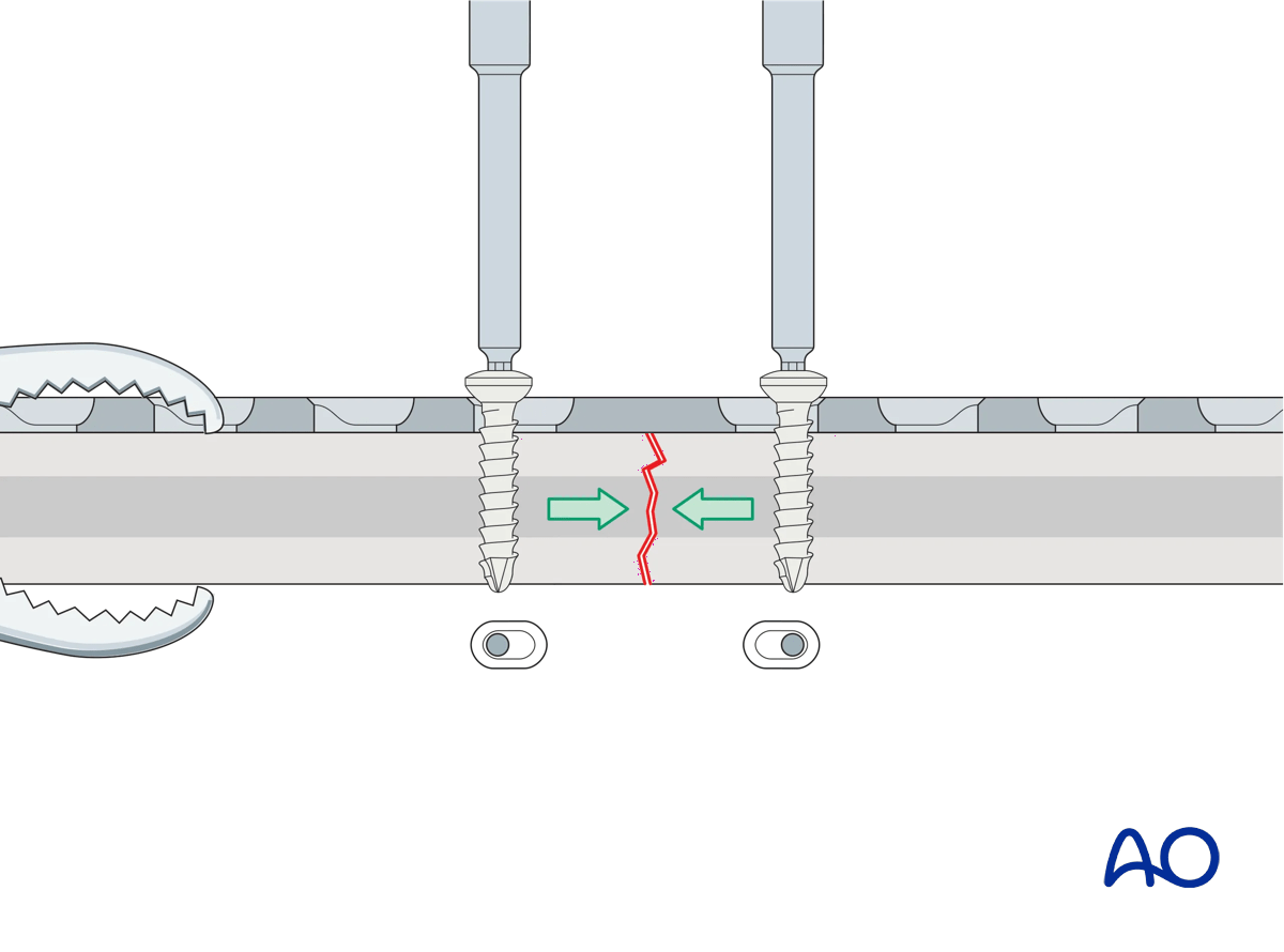
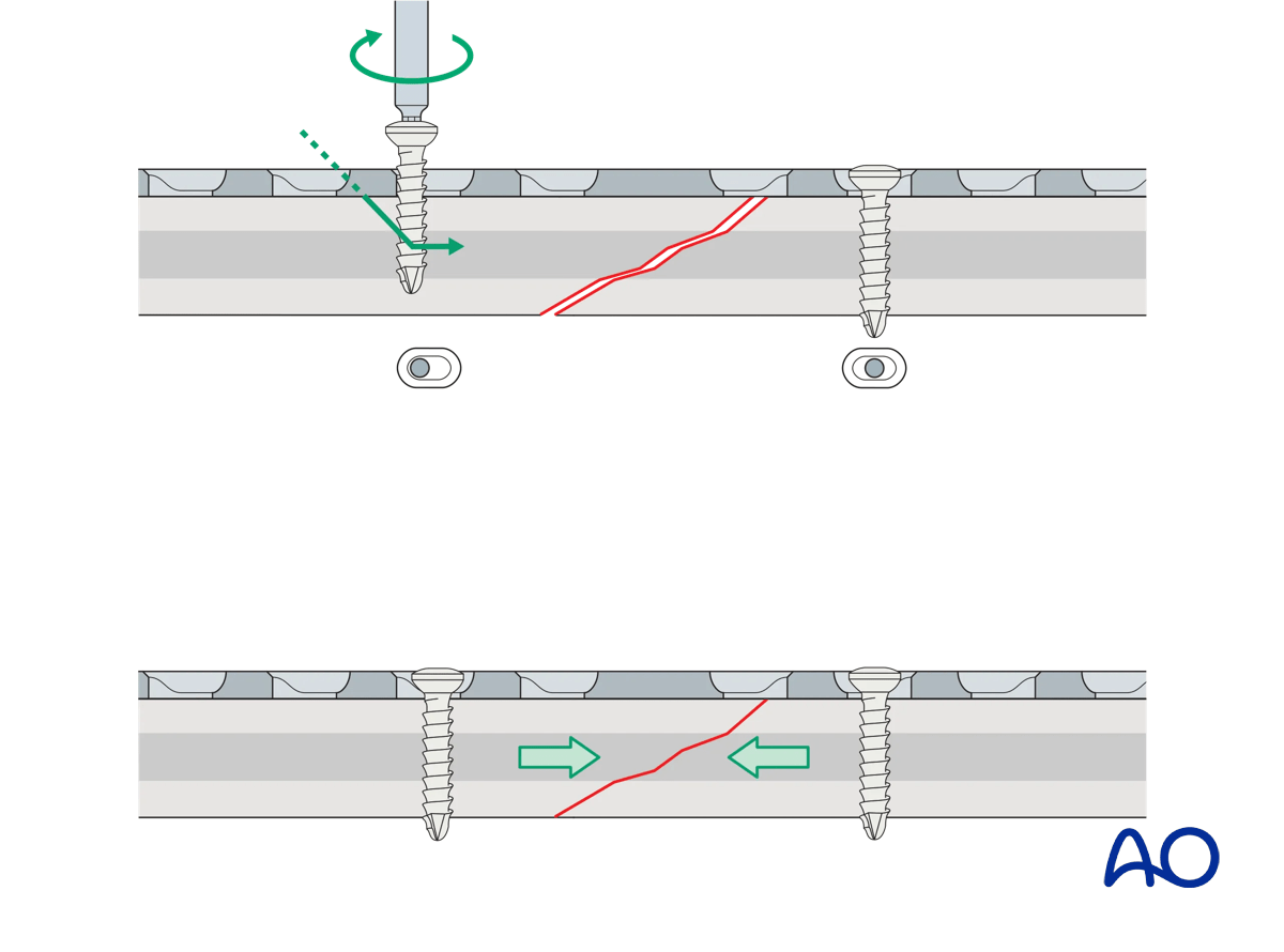
A screw is inserted in compression mode in the opposite fragment. To maintain reduction, it is recommended to tighten the screws gradually by alternating between the two sides.
This 3D model shows screw insertion in compression mode with an overbent plate (Step 2).
The displaced fragment is reduced with the insertion of the second screw eccentrically in compression mode, straightening the plate and closing the gap at both the near and far cortices.
These 3D models show that locking screws cannot be used for compression. The bottom panel shows that locking screws cannot be inserted eccentrically in compression mode, unlike conventional screws (top panel).
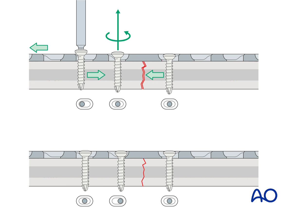
If a fracture gap remains after insertion of the two compression screws, a third screw can be inserted in compression mode. This can be located on either side of the fracture. Before this screw is tightened, the compression screw already placed in the same fragment needs to be loosened. Once the third screw is fully tightened, the loosened screw is re-tightened. Additional screws are then inserted in neutral mode.
Application of dynamic compression plate to transverse fractures.
Application (oblique fractures)
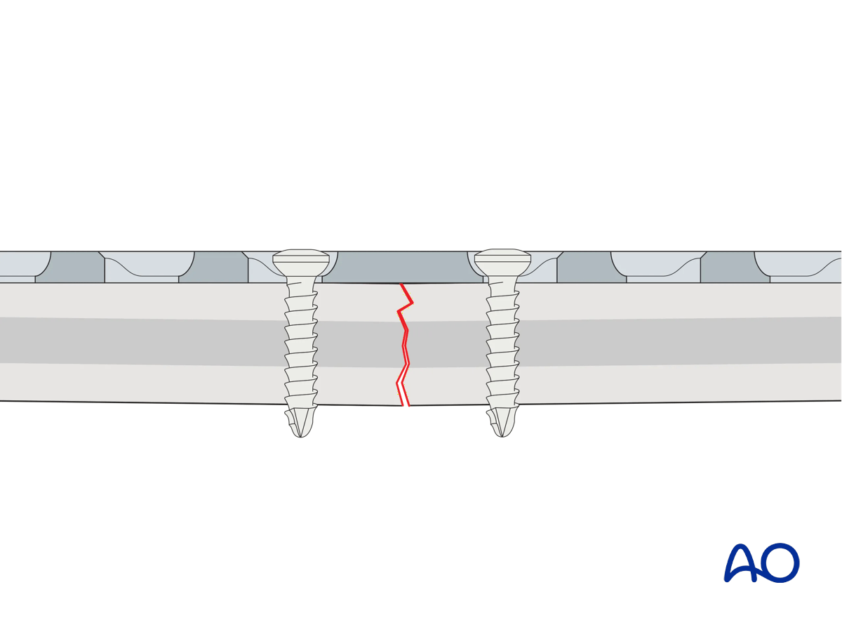
In oblique fractures, place the plate and stabilize it with one or more screws inserted in neutral mode to create a stable base (“axilla”) with one of the bone fragments.
This 3D model shows screw insertion in neutral mode.
In oblique fractures, first the plate is placed and fixed with one or more screws inserted in neutral mode into the first fragment.
Application of dynamic compression plate to oblique fractures.
Insert a screw into the second fragment in compression mode. This drives the second fragment against the axilla and compresses the fracture.
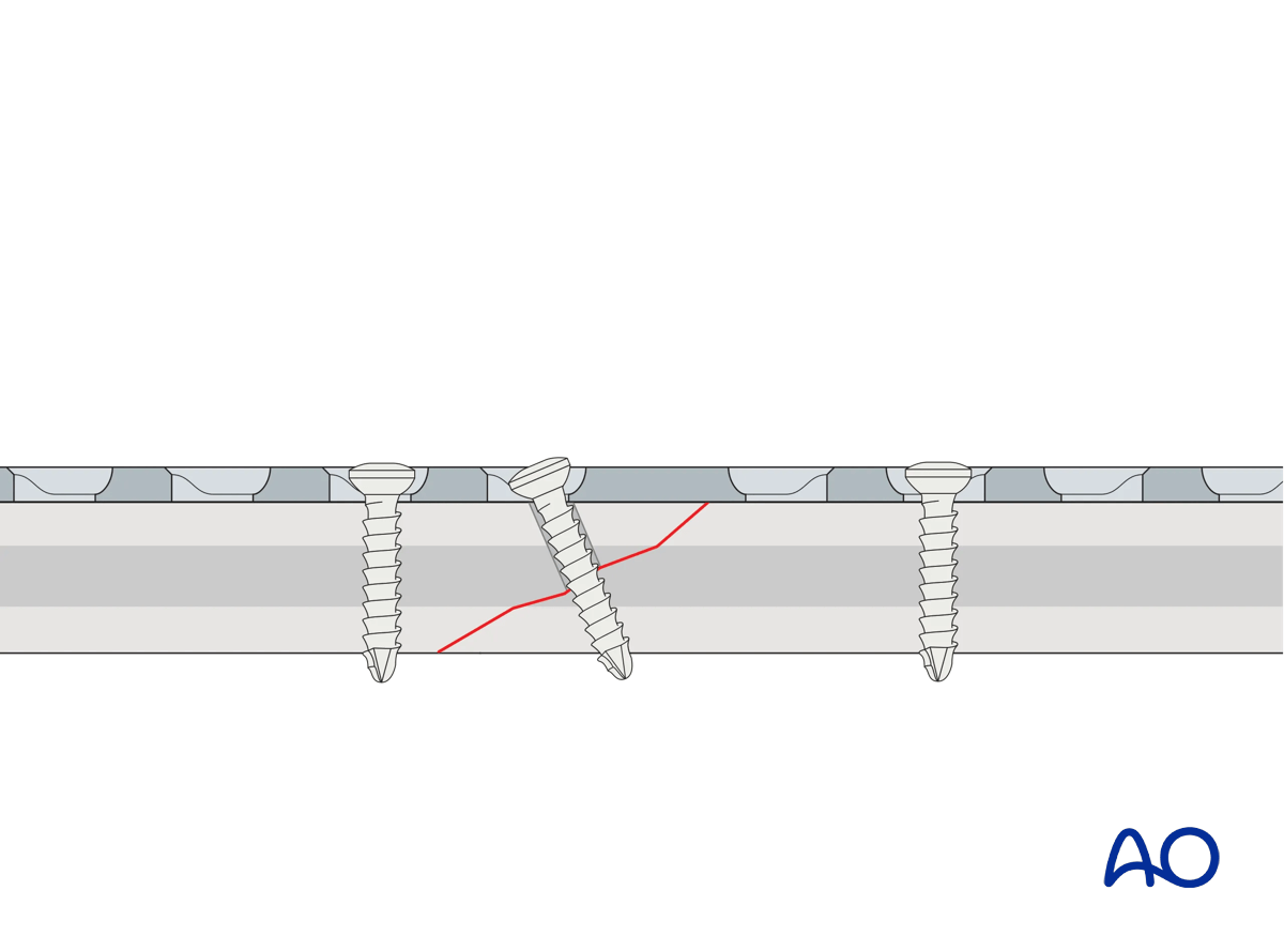
This 3D model shows screw insertion in compression mode.
When inserting a screw in compression mode into the second (mobile) fragment, the fragment is driven into the angle formed by the fracture plane of the fixed (static) fragment and the undersurface of the plate (this is known as the axilla, highlighted in green) and the fracture is compressed.
If the plate is applied to an oblique fracture without creating an axilla, the fracture may displace as it is compressed.
If the fracture pattern and location do not allow an axilla to be created when applying the plate, it may be better to apply a lag screw and a neutralization plate.
If the plate is applied to an oblique fracture without creating an axilla then, when a screw is applied in compression mode, the fracture may displace. The apex of the mobile fragment is not “captured” by an axilla.
For the axilla concept to be applied:
- the plate must be orientated so that the direction of applied (compressive) force is co-aligned with the neutral axis of the bone
- the plane of the fracture must be close to perpendicular to the applied force
- the plate should be placed over the apex of the mobile fracture fragment
If the fracture pattern and location do not allow an axilla to be created when applying the plate, it may be better to apply a lag screw and a neutralization plate.
A lag screw can, in some cases, be inserted through the plate to provide additional compression.
These 3D models show a lag screw with a neutralization plate rotated 90° and aligned with it.
A neutralization plate can reduce the stresses on the lag screw. However, the positioning of the plate has only a minor influence on the screw, as demonstrated by the models.
Here compressive stress is shown in red and tensile stress is shown in blue.
4. Bridge plates
Function
Bridge plating techniques are used for multifragmentary long bone fractures where intramedullary nailing or conventional plate fixation is not suitable.
The plate produces relative interfragmentary stability by providing fixation of the two main fragments at the correct length, and with acceptable transverse and rotational alignment. The fracture site is left undisturbed, and fracture healing by callus formation is promoted.
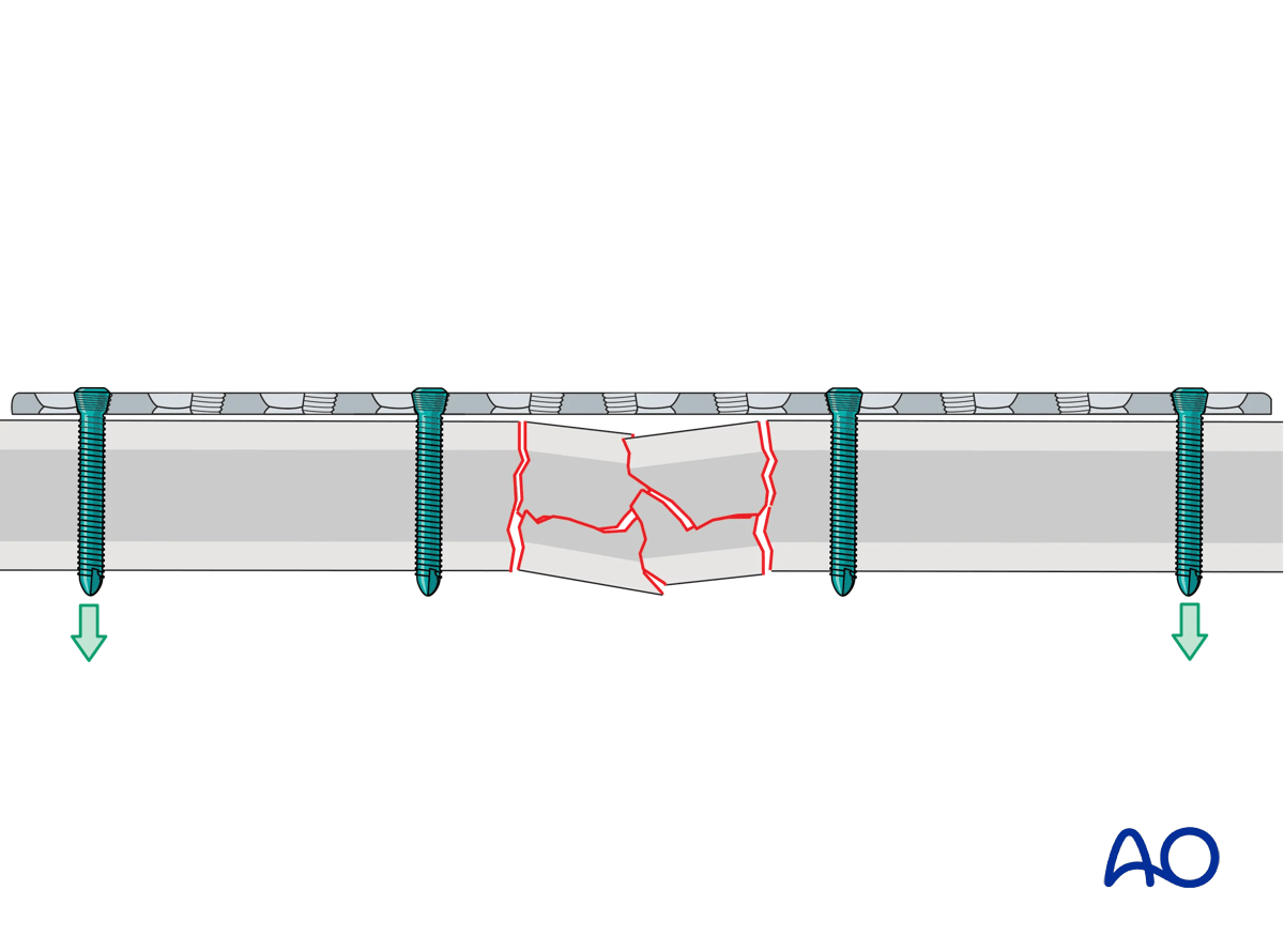
This 3D model shows application of a bridging plate with locking screws.
The applied external force is transduced from one bone segment to the other via the plate and screw construct (primarily the inner screws). The plate has the function of a locked internal fixator, splinting the fracture. If the fracture gap closes (shown in the bottom panel), load sharing occurs and the force transmission is distributed between implant construct and the bone itself.
Compressive stress is shown in red and tensile stress is shown in blue.
Conventional vs locking screws
Either conventional or locking screws may be used.
These 3D models show the insertion of a locking screw (top panel) and a conventional screw in neutral mode (bottom panel).
The conventional screw is inserted in neutral mode and pulls the plate against the bone. Locking screws engage in the plate using the threads and therefore the plate is not pressed against the bone.
These 3D models show the difference between inserting locking screws (top panel) and inserting conventional screws eccentrically (bottom panel).
The eccentric insertion of the conventional screw creates relative movement between the bone and the plate in addition to pressing the plate against the bone.
Locking screws have the following advantages when compared to conventional screws:
- They provide more stability by reducing the risk of screw pullout and over-tightening of the screws
- Well reduced fractures stay reduced
- Unicortical screws may be used
- The plate does not need to be perfectly contoured to the bone
- As the plate is not pressed against the bone, periosteal perfusion is not compromised
These 3D models allow bending of locking screws and conventional screws to be simulated.
The fixed angle locking construct (bottom panel) provides considerable stability and there is bending of both the screw and the plate. In contrast, the conventional screw (top panel) can freely rotate in its plate hole without causing deformation.
High stress is shown in red and low stress is shown in green.
Extent of surgical approach
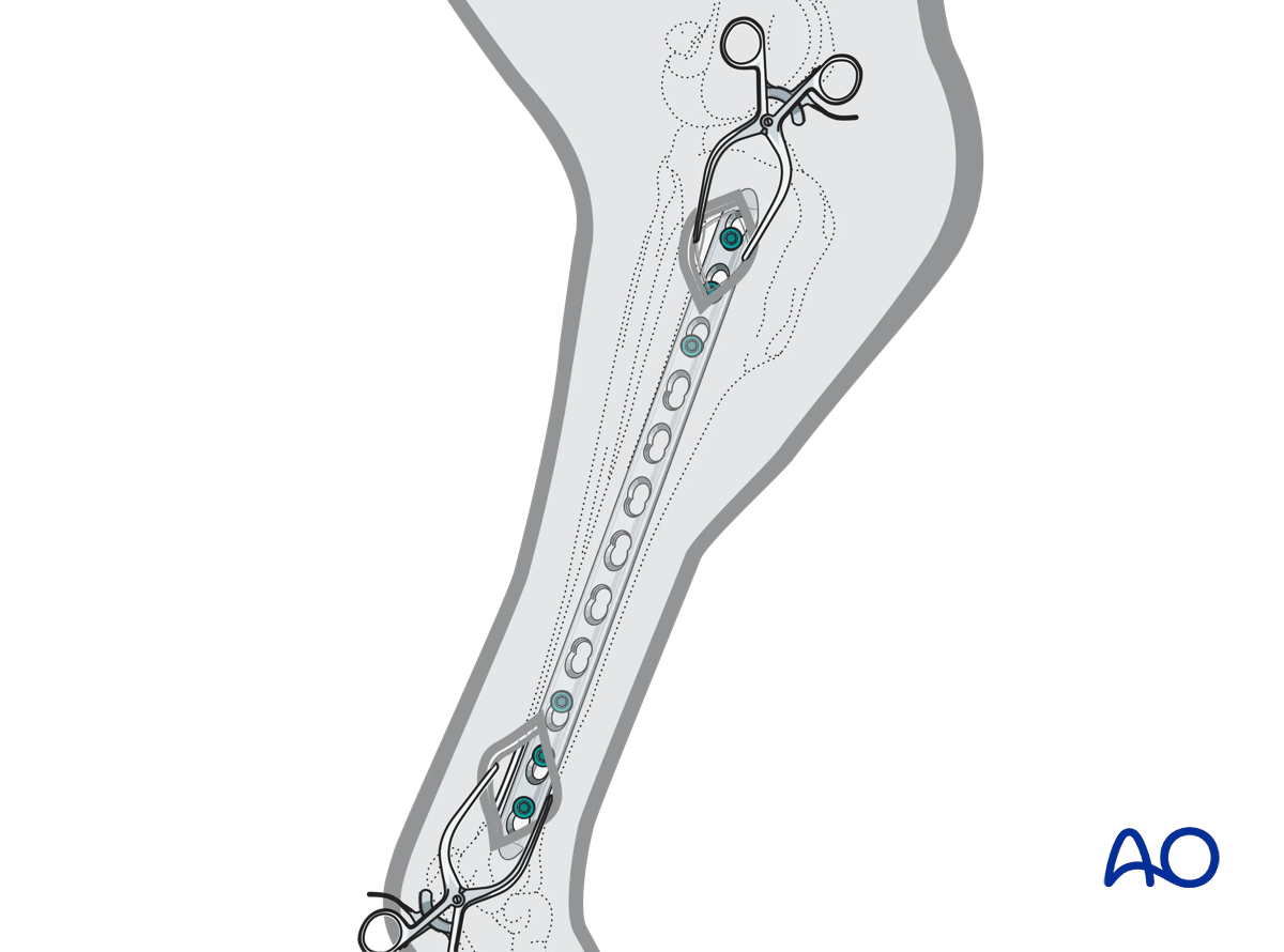
To disturb the fracture site as little as possible, bridging plates are often inserted through a minimally invasive approach (MIPO).
Screws are either inserted through a limited approach, only exposing the plate sufficiently for screw insertion, or through small stab incisions.
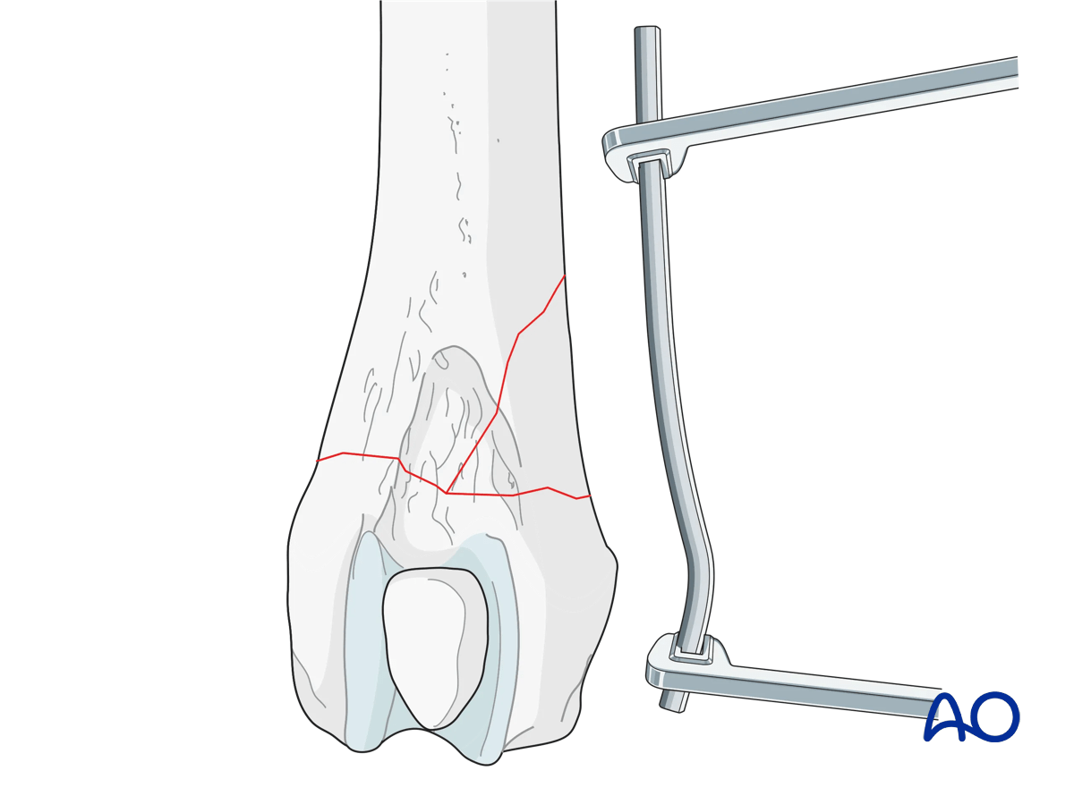
Reduction
Reduce and secure the main proximal and distal fragments in correct length, alignment, and rotation.
This is typically achieved using indirect reduction tools and techniques such as:
- Temporary external fixation
- Reduction devices, eg, pointed forceps
- Traction
Indirect reduction allows manipulation of the main fragments into the correct position without opening the fracture site, thus minimizing further damage to the blood supply.
Especially with multifragmentary fractures, the use of an external fixator, or distractor, can provide alignment and temporary stability for bridge plating without disturbing the soft tissues at the fracture zone.
Pins should be located carefully to avoid interference with the later plating procedure.
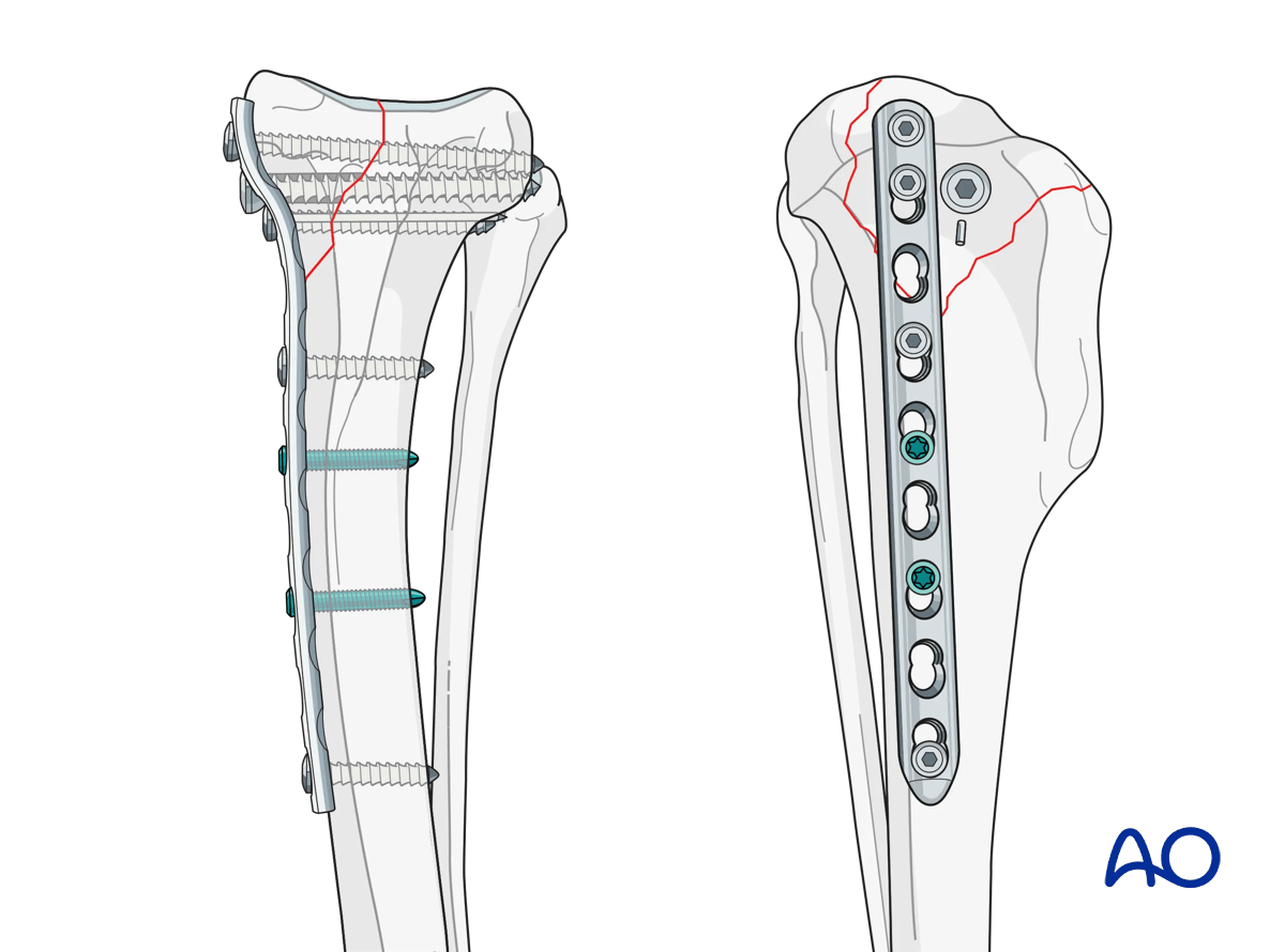
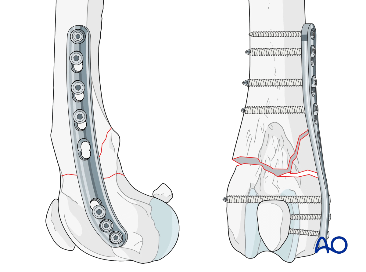
5. Buttress (antiglide) plates
Function
Buttress plates are used to manage partial articular fractures. They are used to supplement lag screw fixation of metaphyseal shear or split fractures in the metaphyseal regions. Lag screws may be inserted either through or outside the buttress plate.