Planning for IS screw insertion
- 1/10 – CT analysis
- 2/10 – Essential C-arm Views for ISS
- 3/10 – Patient-specific inlet & outlet views
- 4/10 – Intraoperative C-arm imaging
- 5/10 – Location of S1 nerve root tunnels
- 6/10 – Anatomic variations
- 7/10 – Normal vs dysmorphic sacral anatomy
- 8/10 – Features of dysmorphic pelvis
- 9/10 – Safe screw channels for patients with normal anatomy
- 10/10 – Safe screw channels for patients with dysmorphic sacrum
1. CT analysis
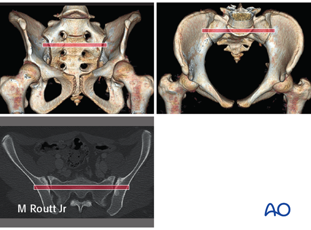
High quality pelvic CTs are crucial for planning reduction maneuvers and safe, effective paths for ISS placement.
In addition to axial images, sagittal and coronal reconstructions should be studied, with x-ray or CT views of the entire pelvis, including 3-D images if available.
Comprehensive imaging demonstrates each site of injury, including its displacement and signs of instability, as well as baseline anatomic features, including bone quality and morphology.
2. Essential C-arm Views for ISS
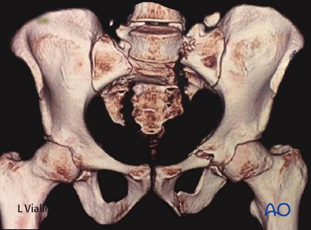
In addition to proper AP, inlet, and outlet views, a true lateral radiograph centered on S1 is essential for IS screw insertion.
The true lateral x-ray shows the midline profile of the sacral promontory, and the iliac cortical densities, which mark the anterosuperior surface of the ala.
A true lateral view is confirmed when the sciatic notches are superimposed.
C-arm set-up, and resulting images should be finalized after the patient is anesthetized and positioned, before sterile drapes are applied.
3. Patient-specific inlet & outlet views
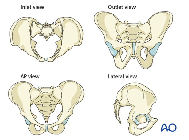
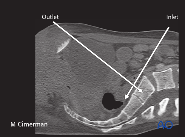
Individual variation of pelvic inclination is significant enough that customized inlet and outlet angles should be chosen for use based upon a midline sagittal CT reconstruction of the sacrum. The inlet angle should be tangential to the anterior cortex of S1. The outlet angle is perpendicular to S1 body at the midline. The C-arm must be centered over the site of interest.
An optimal outlet view shows the upper border of the pubis overlying the second sacral vertebra.
4. Intraoperative C-arm imaging
During setup for surgery, it is important to confirm the adequacy of C-arm imaging. This is essential to avoid errors in ISS placement.
The following should be clearly identifiable:
- sacral foramina in outlet view
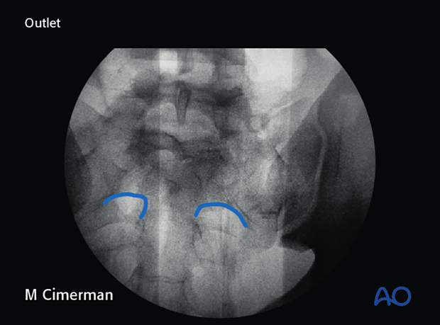
- spinal canal on the inlet view
- S1 body on the inlet view
If these structures cannot be clearly seen, a safe trajectory for the iliosacral screw cannot be determined. Fluoroscopically guided fixation must be replaced with an open procedure. (Obese patients, extensive bowel gas, and/or overlying radiographic contrast material are typical problems.).
5. Location of S1 nerve root tunnels
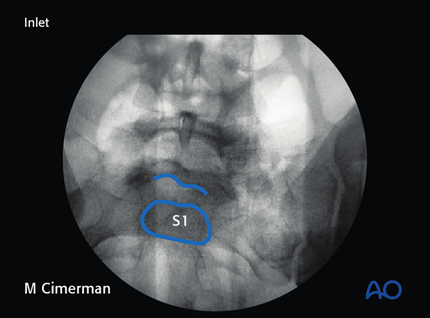
Good quality fluoroscopic views indicate the course of upper sacral nerve root tunnels.
In the outlet view, the appearance is similar to a hip spica cast, with its upper part formed by the midline sacral spinal canal, and the root tunnels being the legs of the spica.
In the inlet view, the root tunnels travel from central to anterolateral, exiting through anterior cortical lucencies.
On the lateral view the S1 root tunnel is caudal/posterior to the iliac cortical density, beneath the superior cortex of the sacral ala.
6. Anatomic variations
Variable in utero segmentation of the lumbo-sacral somites produces abnormal (“dysmorphic”) upper sacral anatomy in approximately one-third of patients. These variations must be recognized because they compromise normally safe intraosseous pathways for ISS.
7. Normal vs dysmorphic sacral anatomy
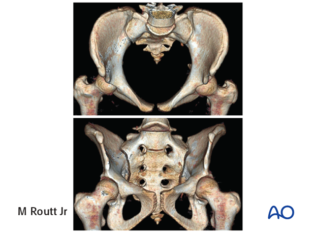
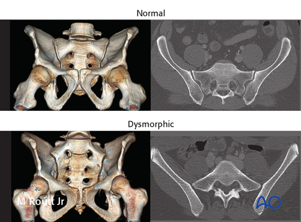
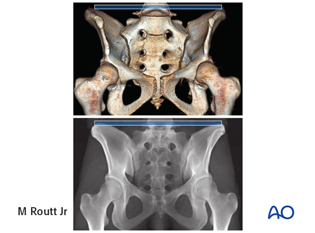
The upper images show a normal pelvis; the lower ones are of a dysmorphic pelvis.
Notice, on the 3D CTs, the differences in sacral alar anatomy, with corresponding upper sacral segment deficiencies on the dysmorphic axial CT view.
In such cases, the second sacral level may be better for an iliosacral screw
8. Features of dysmorphic pelvis
Sacral deformities may be unilateral or bilateral. Bilateral dysmorphism may be symmetrical, or not.
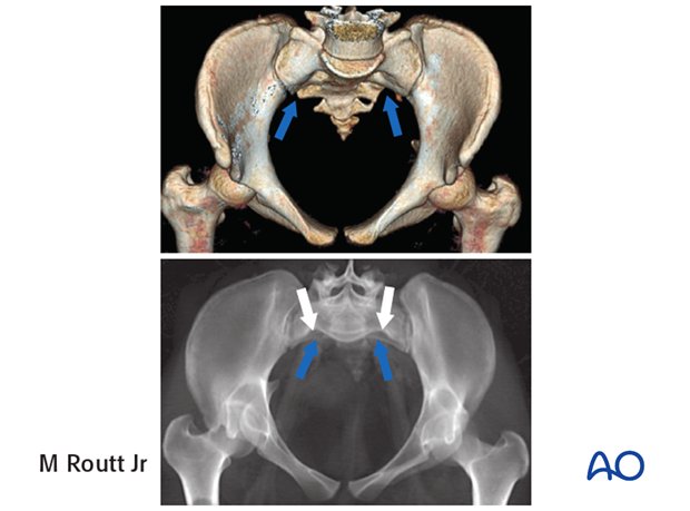
This case shows an individual with symmetrical upper sacral dysmorphism.
The lumbosacral disc is near the level of the iliac crests, not below them as is normal. There is a residual disc between the upper and second sacral segments. The uppermost anterior sacral foramina are not round, as the lower ones are. The superior alar slope is steeper, from medial to lateral, and from posterior to anterior.
The upper sacral alar anterior cortical limit appears as an indentation (white arrows) relative to the alar anterior cortical limit of the second sacral segment (yellow arrows). The upper and second sacral alar anterior cortical limits are different but easily seen on the inlet view. The surgeon must understand these differences and then visualize them under image intensifier in the operating room because iliosacral screws must remain posterior to these alar cortical limits.
9. Safe screw channels for patients with normal anatomy
For fixation of sacral fractures in a nondysmorphic pelvis, an ISS can be placed in the blue channel.
A second screw can be added, through the smaller (posterior) red channel, to increase fixation stability.
A third screw, if required, may be placed transversely through a channel in the upper anterior second sacral body.
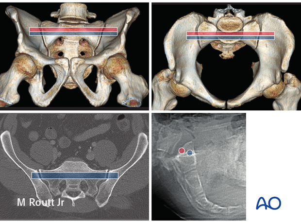
These images illustrate the channel for an S2 transsacral screw in a normal pelvis.
10. Safe screw channels for patients with dysmorphic sacrum
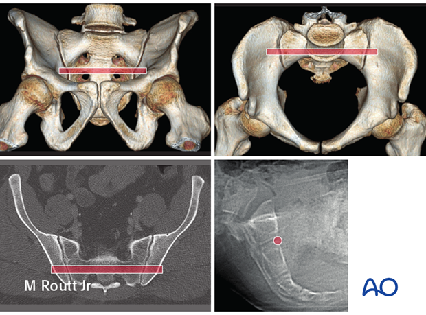
In this dysmorphic pelvis, the red channel is placed through an adequate S2 segment, rather than the dysmorphic first segment.
Upper left - Outlet: the pathway is slightly cranial to the second sacral neural foramina.
Upper right – Inlet: the 2nd sacral segment lacks the anterior indentations of the 1st .The anterior cortical surface of the 2nd is visible anterior to the indentations of the 1st.
(If upper sacral segment (oblique) screws are also desired, they should be inserted before the second segment transsacral screw, since the latter screw prevents visualization of the upper segment anterior alar indentations, which are the anterior limit to safe upper segment screw placement)
