Peri-implant fixation options
1. Introduction
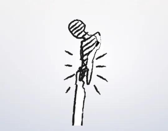
In the peri-implant area standard screw application may be jeopardized by the presence of the stem. In this situation, the following techniques may be used:
- Off-axis screws on either side of the implant
- Cerclage cables/wires
- Unicortical screws
- Locking attachment plate
2. Off-axis screws
When humeral component shape permits, bicortical screws are inserted, alternating on both sides of the stem. This is the preferred plate fixation option.

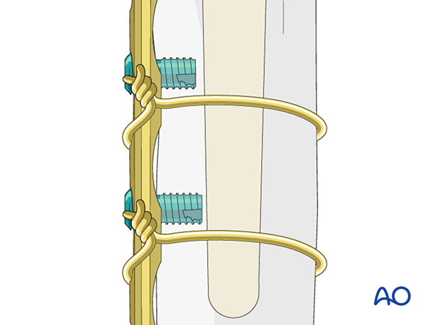
3. Cerclage cables/wires
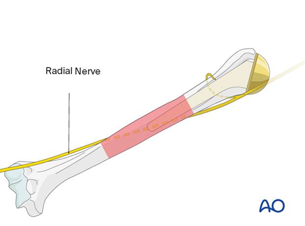
The position of the radial nerve must be considered when placing cerclage cables or wires around the humerus.
Pay particular attention to the middle third of the humerus where the course of the radial nerve lies in the spiral groove.
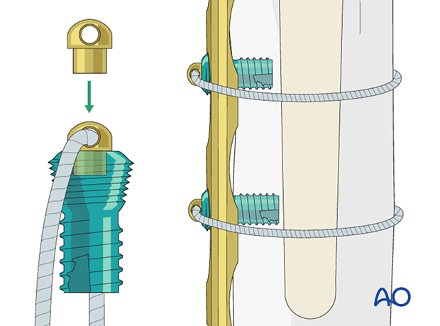
Cerclage plate fixation devices are available for some types of plate.
Cerclage cables or wires should be used in conjunction with unicortical locking screws where possible, to allow rotational stability.
4. Unicortical locking screws
When bicortical screws are not an option unicortical screws can be inserted. These allow plate fixation and rotational stability but have low pull-out resistance.
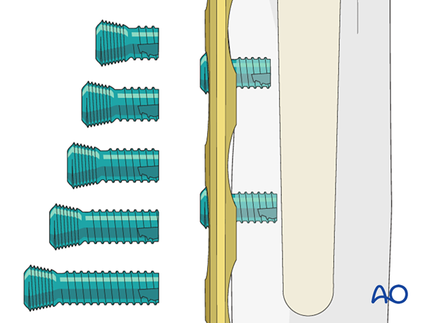
Unicortical locking screws may be used in conjunction with cerclage cables or wires, to avoid plate pull-off.
5. Locking attachment plate
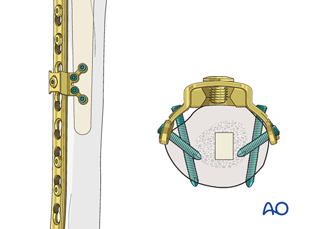
Locking attachment plates can currently only be used with 4.5 mm plate systems. Attention must be paid to the diameter of the humerus in relation to the attachment plate.
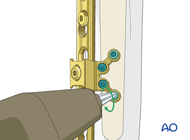
The arms on each side of the locking attachment plate offer the possibility of avoiding the prosthetic stem with 3.5 mm locking or cortex screws. The arms of the attachment plate are usually contoured. However, attention must be paid to the integrity of the locking threads in the plate.
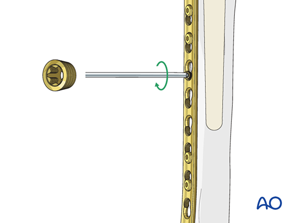
Connection screw
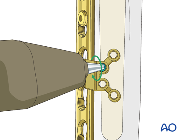
The locking attachment plate is secured to the plate with a connection screw.
The connection screw consists of two parts:
- Upper part
- Conical part
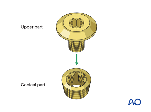
The conical part is screwed to the plate with a torque-limiting screwdriver.
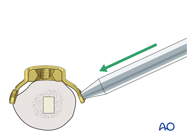
Option: locking attachment plate pre-bending
The locking attachment plate can be pre-bent with a bending pin to adapt to the anatomy of the humerus.
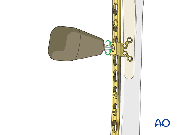
Locking attachment plate positioning
The locking attachment plate is positioned over the selected plate hole and secured by attaching the upper part of the connection screw to the conical part.
Drill sleeves can be screwed in to be used as handles.
The position of the implant is verified under image intensification.
A screw hole is drilled using a drill sleeve and drill bit. The direction of the hole should be checked with image intensification.
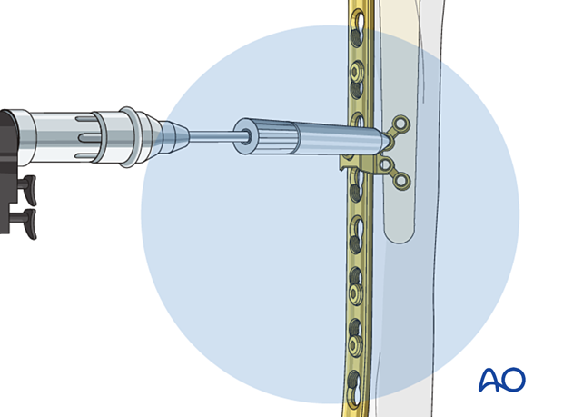
A 3.5 mm locking screw is inserted into the prepared hole and screwed in.
The locking attachment plate is stabilized with additional locking screws.
