Adjunct plate options
1. Introduction
If there is no room for bicortical screw fixation, different options may be used around the component stem to secure the plate:
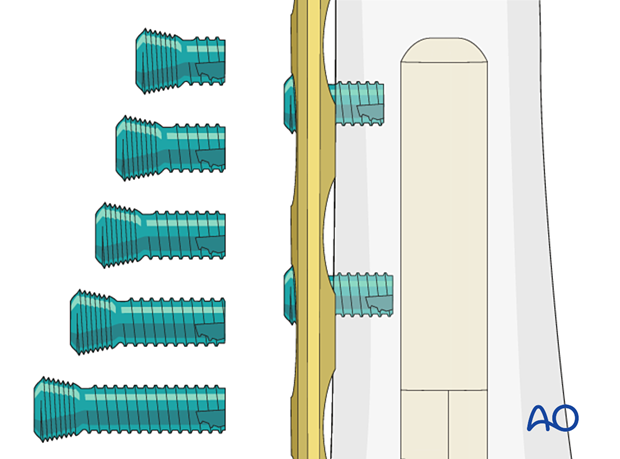
- Unicortical locking screw fixation
- Cerclage cables integrated into the plate
- Locking attachment plate
- Alternative plate systems
2. Unicortical locking screw
Limited options are available for unicortical screws. These are often blunt tip screws that will abut the component stem. The addition of unicortical locking screws creates a length stable construct. These screws should not be used in isolation and must have either bicortical screws or cerclage fixation for adequate lasting stability.
3. Cable anchoring devices
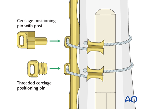
Cable anchoring devices are inserted into unused plate holes or the drive recess of screws. The cerclage cable can be passed through the anchor.
Cerclage buttons
Seat in screwhead recess to resist pullout of the screw plate construct.
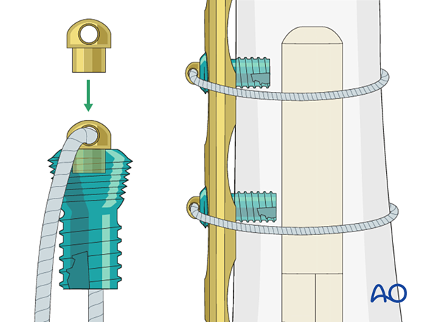
Cerclage positioning pins
Seat directly into an empty plate hole to maintain the position of the cable relative to the plate.
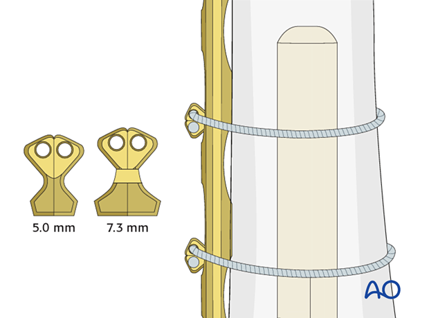
Crimp positioning pins
Combine a cable crimp and positioning pin in one piece. They seat directly into locking holes to maintain the position of the cable relative to the plate.
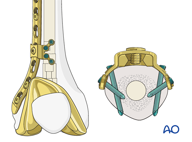
4. Locking attachment plate
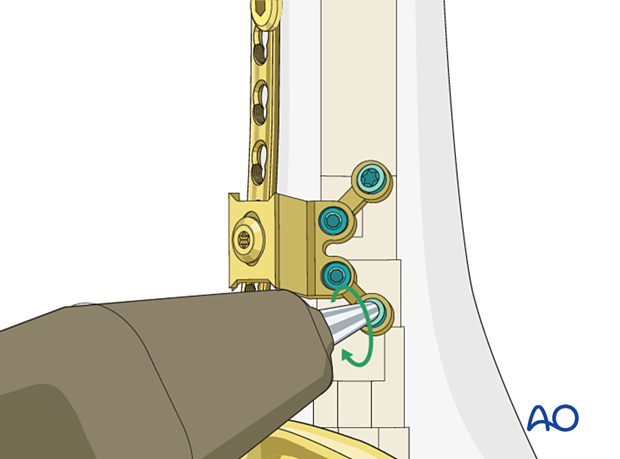
The arms on each side of the plate offer the possibility to avoid the prosthetic stem with 3.5 mm locking or cortex screws. The arms of the attachment plate are usually contoured. However, attention must be paid to the integrity of the locking threads in the plate.
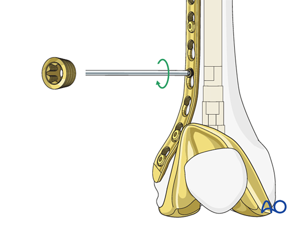
Connection screw
The locking attachment plate is secured to the plate through the connection screw.
The connection screw consists of two parts:
- Upper part
- Conical part
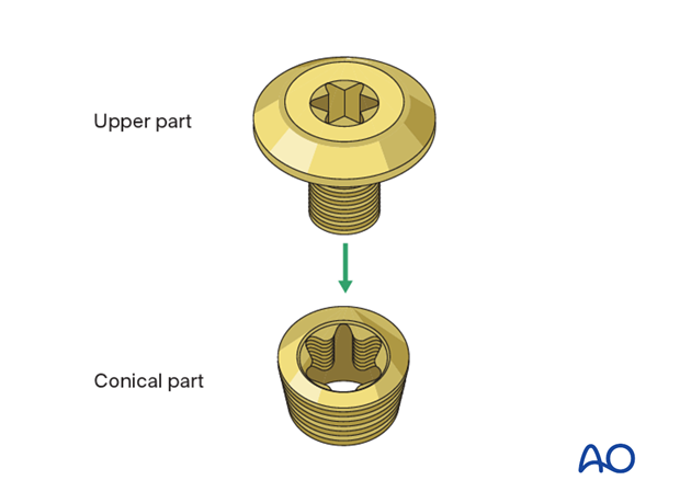
Screw the conical part to the plate with a torque-limiting screwdriver.
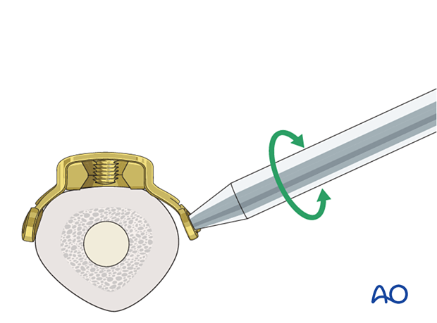
Option: locking attachment plate prebending
The locking attachment plate can be prebent with a bending pin to adapt to the femur anatomy.
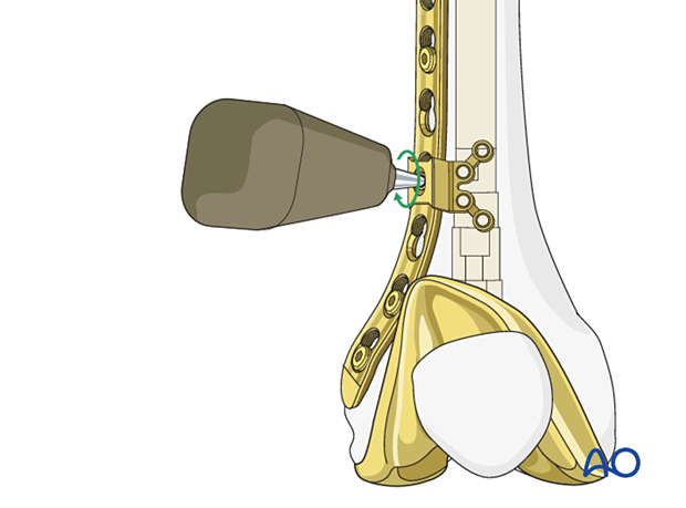
Locking attachment plate positioning
The locking attachment plate is positioned over the selected plate hole and secured into the conical part with the upper part.
Drill sleeves can be screwed in to be used as handles.
Implants position is verified under image intensification.
A screw hole is drilled with a drill bit. The hole direction should be checked with image intensification.
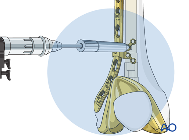
A 3.5 mm locking screw is inserted and screwed in the prepared hole.
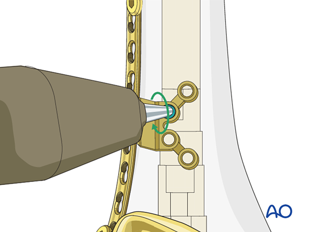
The locking attachment plate is stabilized with additional locking screws.
5. Alternative plate systems
Many different plate designs exist. Some plates offer multiple screw options at each level, utilizing a wider plate.
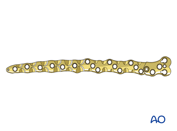
In addition, variable angle screw fixation can provide greater access to the intact bone. This can be done by placing a cortex screw that is converted to a locking screw with a locking cap in some systems. Other plating systems have variability in the locking mechanism that can be used to create a locked screw in a nonstandard plane.
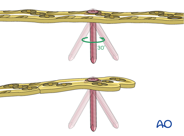
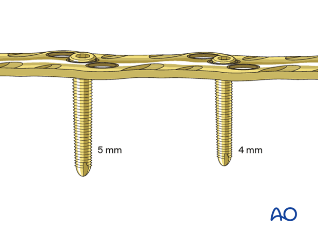
Screw diameter can also be variable within the same plate hole.
