Retrograde nailing
1. Principles
Intramedullary nailing provides stable fixation for early weight-bearing and is usually biologically safe, not disrupting potential for fracture healing. However, some femoral component prosthesis designs do not permit nailing if they have a closed box.
In elderly patients with osteoporotic femoral canals, no, or only minimal, reaming may be required.
The diameter of the nail used is limited by the size of the femoral prosthetic opening. The largest diameter possible should be selected.
2. Patient preparation and surgical approach
Patient positioning
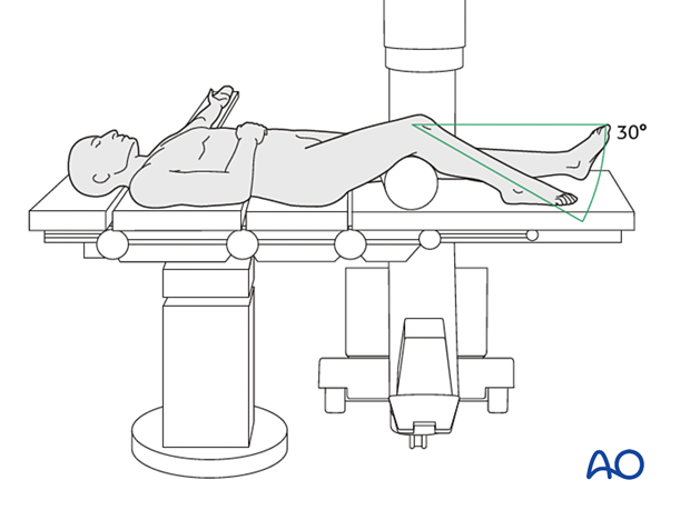
This procedure may be performed with the patient placed supine with the knee flexed 30°.
Surgical approach
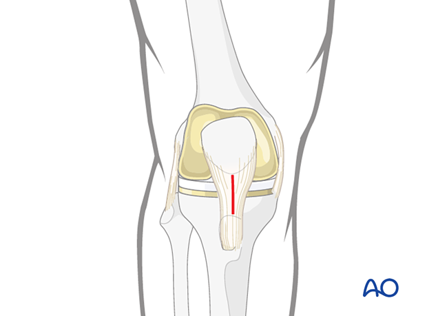
The retrograde nailing approach is used.
3. Reduction
A variety of techniques can be used to aid the reduction of the distal femur.
For most fractures, manual traction would be satisfactory. In some cases, more sophisticated reduction techniques must be used such as:
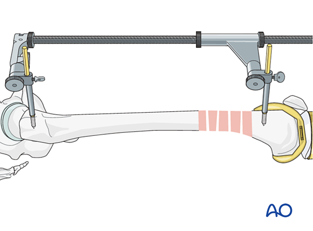
- Femoral distractor
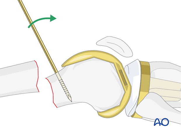
- Schanz screw
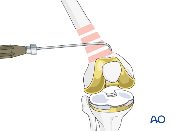
- Bone hook
- Pointed reduction forceps
- Collinear clamp
Rarely, an open reduction is required. If this is preformed, stripping must be minimized.
Main deformities
Three major deformities are managed:
- Varus/valgus: frontal plane alignment is checked by assessing the quality of direct reduction and evaluating limb alignment in comparison with the uninjured site. This is facilitated by prepping and draping both legs.
- Rotation: rotational alignment is checked by assessing the quality of direct reduction and evaluating torsional profile in comparison with the uninjured site. This is facilitated by prepping and draping both legs.
- Flexion/extension (sagittal plane alignment): take care to overcome the deforming force from the pull of the gastrocnemius insertion of the muscle in the distal fragment.
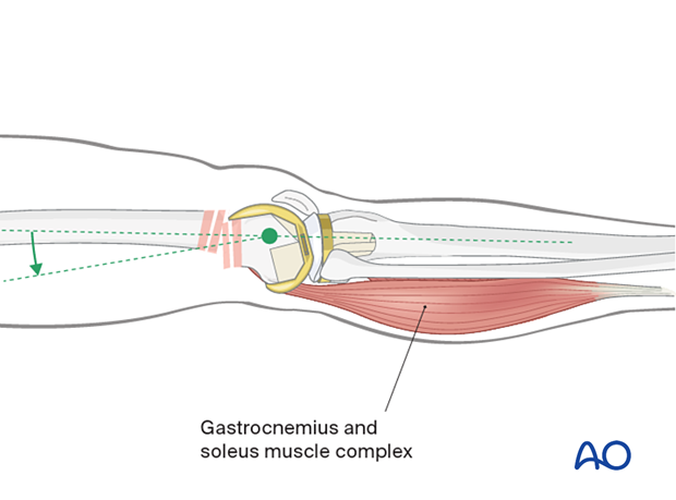
Flexion of the knee over a padded bump is of assistance.
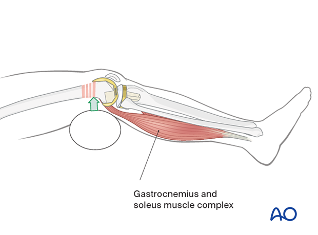
If the fracture pattern allows, a sagittal pin can be used as a joystick in the condylar block to correct flexion/extension before interfragmentary compression is achieved.
Femoral distractor
Schanz screws for the femoral distractor can be positioned so that they are not in the way for the placement of an intramedullary nail. The distractor can apply a powerful distraction force and is more consistent than manual traction.
Bone hook
Direct reduction with a bone hook may be helpful in securing anatomical alignment. Careful insertion and manipulation must be performed in order to minimize soft-tissue trauma and to prevent injury to the femoral artery.
Collinear clamp
Depending on the fracture morphology, reduction of the distal femur can also be achieved using a collinear clamp.
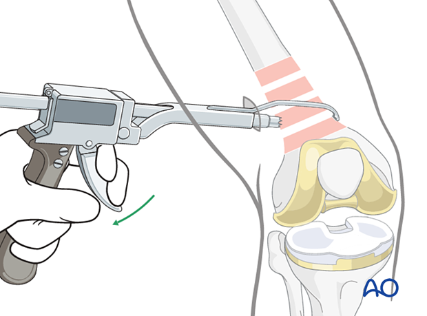
Schanz screw
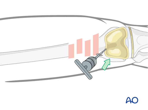
One or more Schanz screws can be helpful for providing direct control of displaced main fragments. It is superior to external reduction maneuvers.
The Schanz screw needs to be positioned medially or laterally, so that it does not obstruct the placement of the intramedullary nail.
Verification of successful reduction
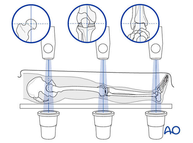
It is important to restore the biomechanical axis of the lower limb. The normal biomechanical axis follows a line from the center of the femoral head, through the center of the proximal tibia, and then through the center of the ankle joint. This axis can be checked intraoperatively by using a piece of cable, such as the diathermy cord. The cord is stretched from the iliac spine across the patella to the cleft between the first and second toes.
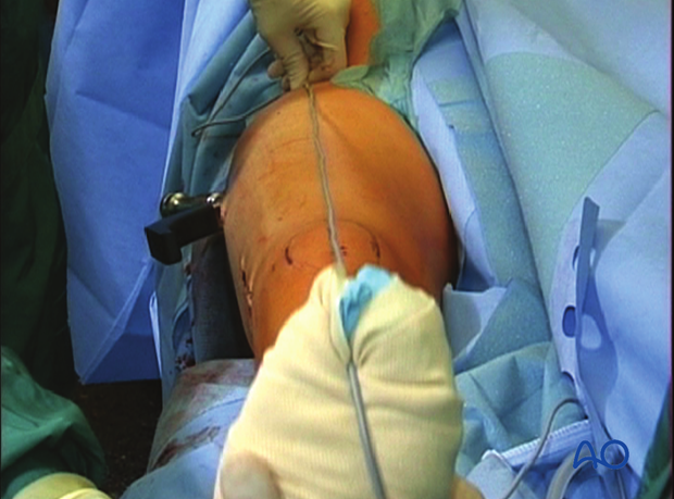
If rotation is correct, this cord will pass over the midline of the patella, and slightly medial to the tibial eminence. The radiological landmarks of the center of the femoral head, the center of the knee and the center of the ankle joint should all be in line if the mechanical axis of the femur is correct.
In simple fractures, rotational reduction can also be assessed by comparing cortical thickness above and below the fracture.
Not only must the biomechanical axis be restored, but care should be taken to ensure that there is no malrotation of the distal femur on the proximal femur.
Poller or blocking screw
The concept of a blocking (poller) screw is based on the principle that the malalignment induced by oblique, proximal and distal fractures can be counteracted by the nail-directing effect of the screw. Therefore, its position should aim to counteract the anticipated displacement of the fracture. Most often, it is therefore inserted in the short side in the distal fragment. If there is a wide canal, two screws can be inserted, one on either side of the path of the nail. It is technically challenging to insert the blocking screw in the correct position. On one hand, the screw should prevent reaming in the undesired location. On the other hand, it should not impede the reaming process, or nail insertion.
It is better to insert the blocking screw prior to reaming and, in cases of unreamed nailing, prior to nail insertion, in order to provide adequate contact between the nail and the screw. If the blocking screw is inserted after reaming, the path of the nail is already set, and the blocking screw may not function.
The reaming process in the presence of the blocking screw must be performed very carefully in order not to damage the reamer tip or the screw.
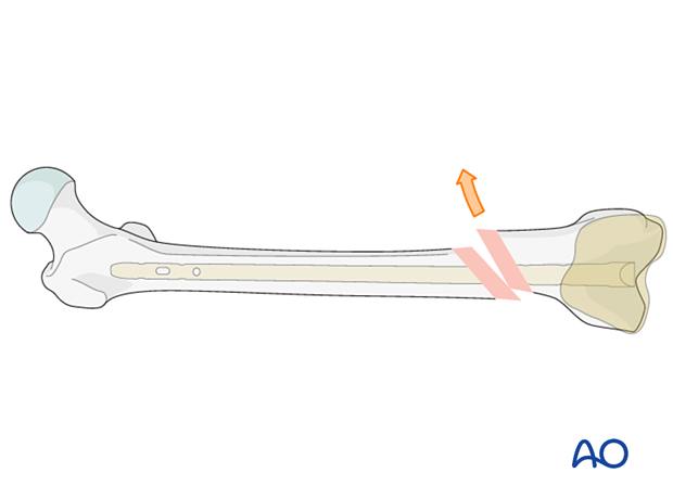
The blocking screw should be located according to the direction of the initial fracture displacement. Therefore, with medial displacement, the fracture will try to displace medially even after the reduction and a blocking screw should be placed lateral to the proposed nail track.
When there is a wide canal, a blocking screw can be placed on each side of the proposed nail path.
4. Choice of implant
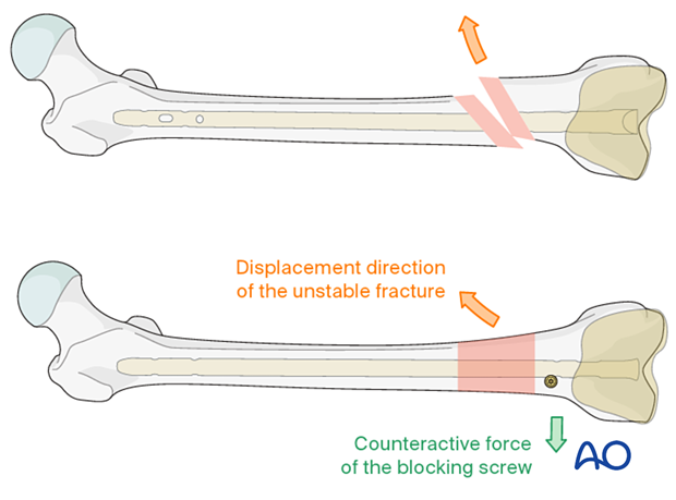
The guide wire is inserted into the predrilled entry portal. Advancement into the proximal main fragment is usually easier than in antegrade nailing and is performed under image intensifier guidance.
The guide wire is inserted up to the area of the lesser trochanter, where it will have good purchase and preventing movement during reamer exchange.
Nail length
Variations in surgical preferences exist regarding the optimal length of a retrograde nail for treatment of a distal femoral fracture.
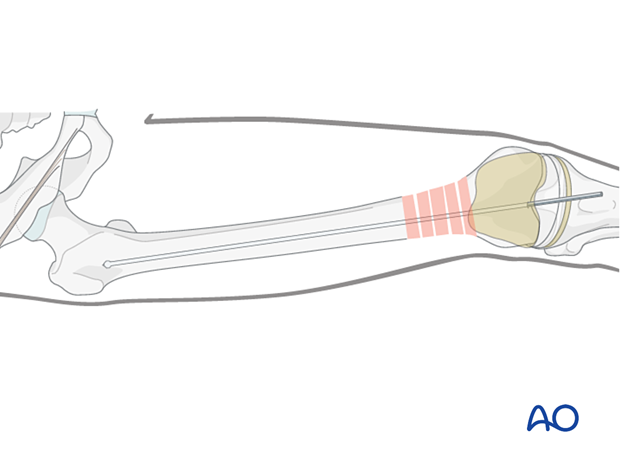
The retrograde nail usually should terminate at the level of the lesser trochanter. A nail that is any longer will create a stress riser at the level of the femoral neck. A nail that is any shorter will end in the diaphysis where locking is more difficult.
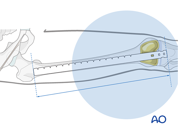
The length of the nail is determined by comparing a second identical length guide wire to the one that has been inserted. The correct placement of the guide wire in the proximal canal should be assessed via image intensifier. Additionally, the second guide wire must be positioned in contact with the articular surface of the distal femur. This must be verified by image intensifier as well.
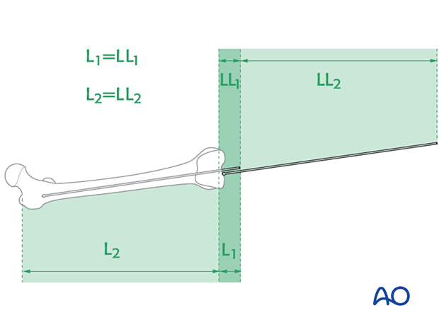
It is important to visualize the fracture zone by image intensifier to carefully ensure that adequate femoral length has been maintained.
If the fracture is fragmented and length is not known, measure the normal leg and select a nail to match.
The ruler should lie in the center of the distal end of the femur at the roof of the intercondylar notch and along the center of the medullary canal.
Nail diameter
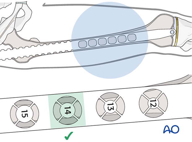
Assess the nail diameter radiographically or select a nail diameter 1.5 mm narrower than the largest reamer head used.
5. Reaming
Sequential reamer size increase
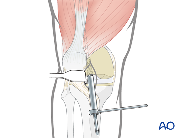
If reaming is undertaken, begin with an end-cutting medullary reamer. Use a tissue protector guide to prevent damage to the prosthetic components.
It is critical to identify the dimensions of not only the femoral aperture, but also the geometry of the plastic insert when planning the canal preparation to avoid damaging the prosthesis and to determine the maximum nail diameter to employ. Damage to the tibial tray might necessitate revision of the polyethylene component.
6. Nail insertion
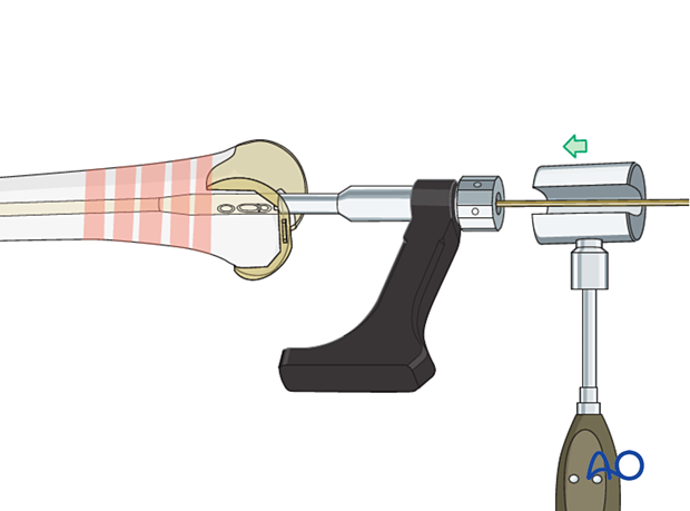
Drive the nail gently into the near fragment. This can often be performed manually. If required, gentle hammer taps are usually enough to ensure proper advancement. Insert the nail until it just passes deep to the prosthesis..
Take care in osteoporotic oblique and multifragmentary distal femoral fractures not to shorten the femur by impacting the bone ends too firmly together.
7. Stable distal interlocking
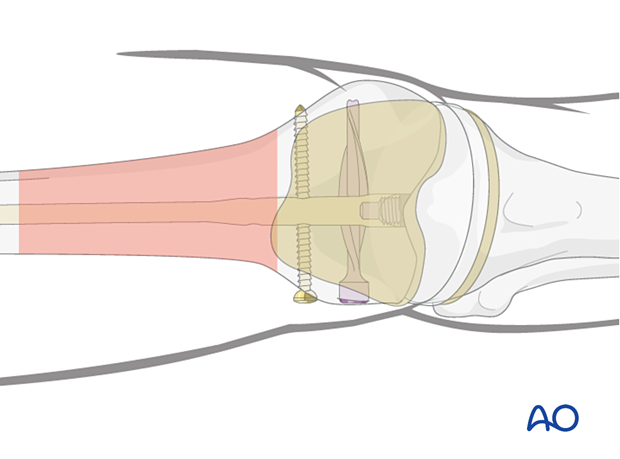
The femoral canal in the distal segment is usually much wider than the nail diameter. Stable distal interlocking is required. This can be achieved with the following options:
- Multiplanar locking screws
- Angular stable interlocking
- A spiral blade to increase surface area (with endcap to achieve angular stable interlocking)
- Secondary placed blocking screws
Further details about these techniques can be found in the dedicated section of the AO Surgery Reference.
8. Radiological assessment of rotation
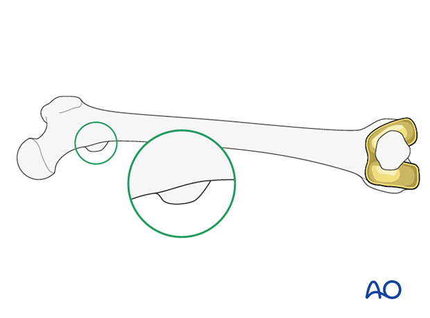
Compare the profile of the lesser trochanter with that of the contralateral leg (lesser trochanter shape sign), holding the leg so that the patella faces anteriorly on both sides.
Before positioning the patient, store the profile of the lesser trochanter of the intact opposite leg (patella facing anteriorly) in the image intensifier.
The illustration shows the lesser trochanteric profile of the intact opposite side.
Malrotation
In cases of malrotation, the lesser trochanter is of a different profile when compared to that of the contralateral leg.
Take care to assess rotation with the patella facing directly anteriorly.

Matching of the lesser-trochanter shape
After distal locking, achieve correction by using the handle of the nail insertion device. The distal main fragment can be rotated in relation to the proximal main fragment.
9. Proximal locking
General consideration
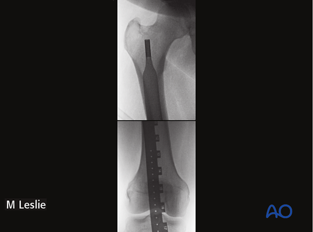
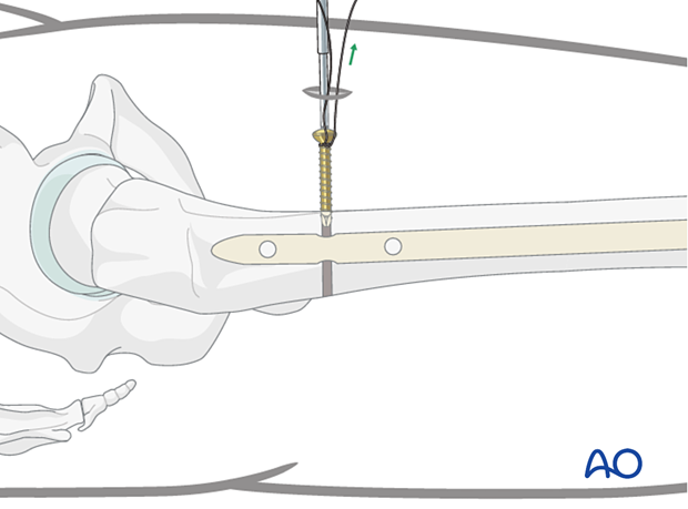
The first proximal locking screw is inserted in the anteroposterior plane. A radiolucent x-ray table is essential. Care must be taken in preoperative planning so that adequate image intensifier views of the proximal femur can be obtained in both the AP and the lateral planes before the operation begins.
The thickness of the subcutaneous tissue, especially in obese patients, can make this procedure technically demanding.
It is extremely difficult to perform lateral to medial proximal locking with a long retrograde femoral nail. This is due to the difficulty in positioning the image intensifier around the proximal femur.
Drilling of screw hole
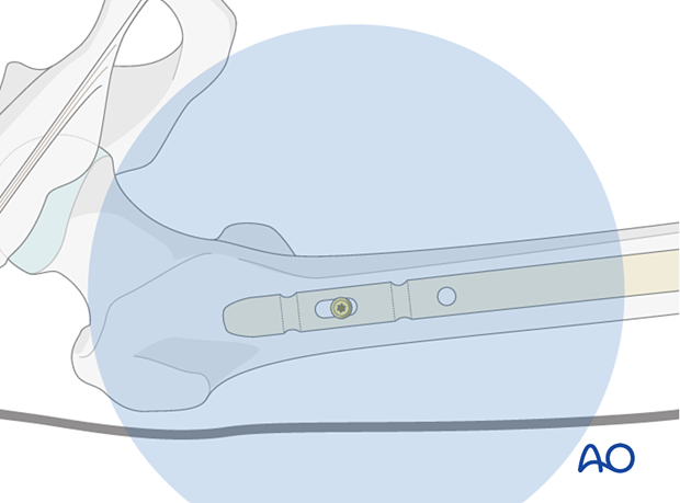
Proximal AP locking must be performed by the freehand method. This is easier to achieve with the leg placed flat on the table after removal of the distal locking jig.
Bring the image intensifier into a strict AP position at 90° to the nail. The proximal static holes must project a perfect circle and the tip of a scalpel is projected into the center of the hole.
Make a 3 to 4 cm skin incision and bluntly dissect the muscle.
Place the radiographic projection of the tip of the drill bit as centered as possible into the hole image. Start drilling but assess the position of the tip of the drill bit repeatedly, with the drill temporarily uncoupled.

Screw insertion
Determine the appropriate screw length with a depth gauge and insert the AP locking screw. Take care to prevent the oblique insertion of a locking screw because it can become trapped between the firm cortex of the proximal femur and the nail.
Second locking screw
Depending on the fracture pattern, use either one or two proximal locking screws. Due to the osteoporosis, a second locking screw is usually desirable.

10. Assessment of alignment and knee stability
Assessment of alignment and knee stability
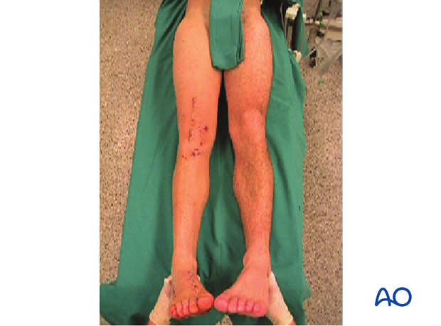
Before the patient is moved from the operating table, observe rotation of the leg clinically and compared it to the contralateral side.
11. Aftercare
Nail fixation permits early full weight bearing postoperatively.
Knee bracing is not essential and should be considered optional for patient comfort.
