K-wire principles
1. General considerations
K-wire fixation may be used for preliminary stabilization of fracture fragments, in addition to stable fixation with screws and/or plates, and in the fracture management of small bones.
It is particularly important in pediatric fracture management near or involving a physis frequently in combination with a cast.
General advantages:
- Cheap
- Universally available
- Can be easily inserted and removed
- Allows for minimally invasive management
- Can prevent redisplacement of fractures treatment with cast
Advantages related to pediatric fracture management:
- Minimal disturbance of physis by K-wires
- Relatively low stress at fracture level due to relatively low body weight and short lever arms
- Relatively fast fracture healing (before loosening of K-wire)
- Good remodeling capacity even if not healing in perfect alignment
Disadvantage:
- Not functionally stable alone
- May injure neurovascular structures if applied incorrectly
Key principles
K-wire size is chosen according to the age of the child and the size of the fragment.
The entry point, together with the correct direction of the K-wire, is the key to optimal fixation.
For most simple fractures, two, occasionally three, K-wires give sufficient stabilization if the K-wires:
- are of the correct size (1.6/2.0 mm),
- do not cross each other at the fracture level,
- are intraosseous.
K-wire osteosynthesis usually requires additional plaster cast protection.
2. Indications
K-wire fixation is indicated for management of:
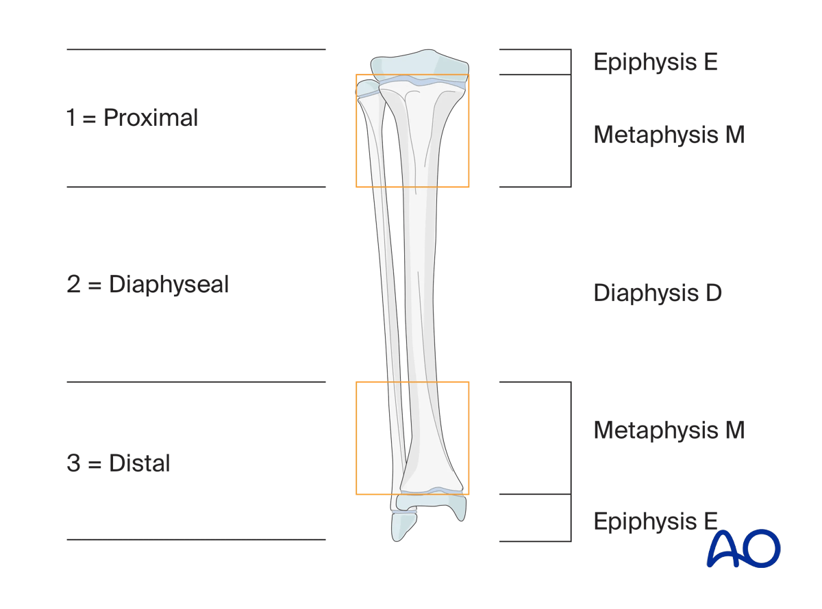
- Fractures in epi-/metaphyseal areas as defined by the AO classification
- Fractures of small bones (eg, in hand and foot)
- Small bony fragments
- Fragment reposition in multifragmentary fractures in addition to stable fixation
K-wire fixation alone is not indicated in:
- Diaphyseal fractures
- Multifragmentary fractures
3. Size of K-wire
The following variables influence the choice of K-wire diameter:
- Patient age/weight
- Fracture location
- Fragment size
- K-wire trajectory
Patient age/weight
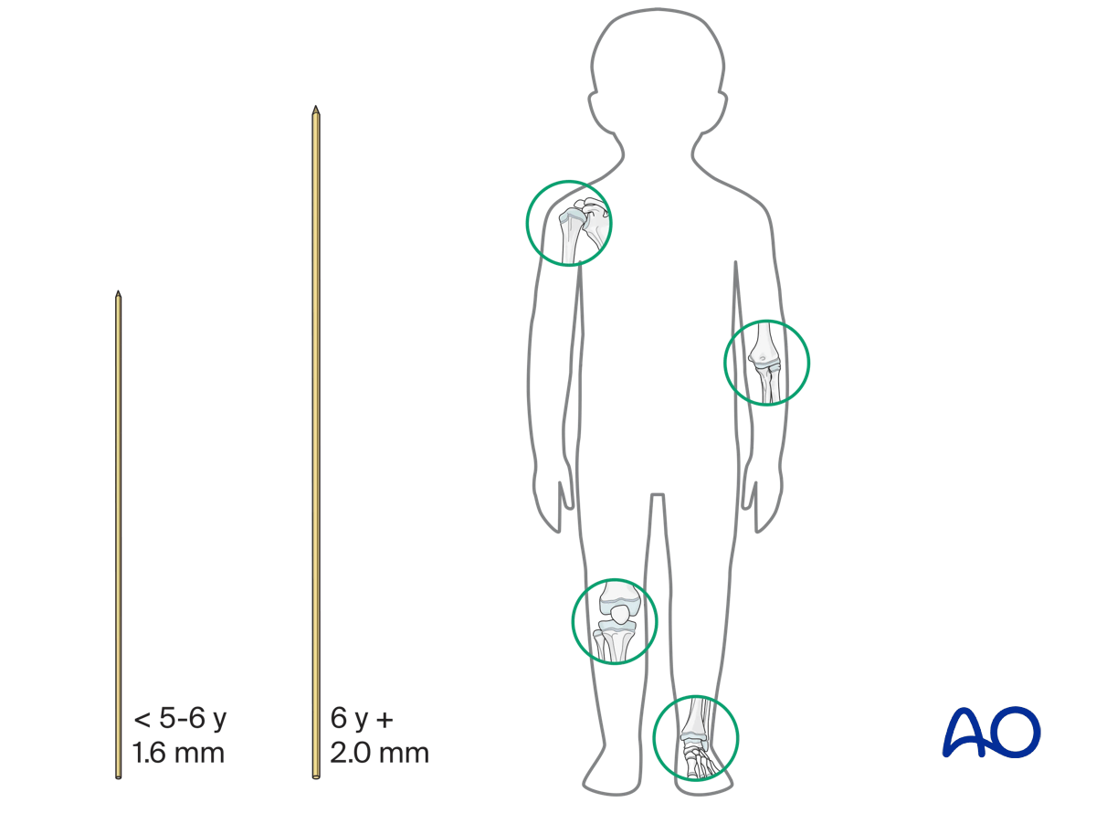
In children younger than 5–6 years, 1.6 mm K-wires are used for fractures around the shoulder, elbow, knee, and ankle joints.
In children above this age, 2.0 mm K-wires are usually used.
It is important to consider the weight of the patient when choosing the diameter of the K-wire.
Fracture location
Metaphyseal fractures of the long bones require at least 1.6 mm K-wires. If only two wires are used, larger diameter wires may be necessary.
Fractures of small bones (hand and foot) require 1.0–1.6 mm K-wires.
Fragment size
The size of the K-wire should be chosen according to the size of the fragment. For example, a fracture of the medial epicondyle of the humerus requires a K-wire of smaller diameter than a fracture of the lateral humeral condyle.
K-wire trajectory
For fractures fixed with two (or three) K-wires from only one side, one size larger K-wires are used than for bilateral crossed K-wiring.
For example, for bilateral crossed K-wiring of a supracondylar humeral fracture, 1.6 mm K-wires can be used, whereas for radial divergent wiring of the same fracture, 2.0 mm K-wires are preferable.
4. Planning
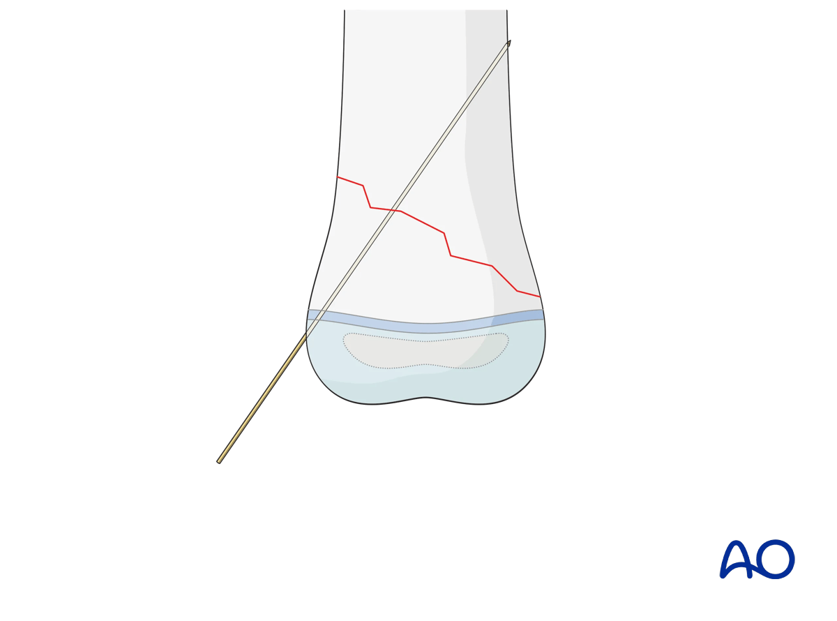
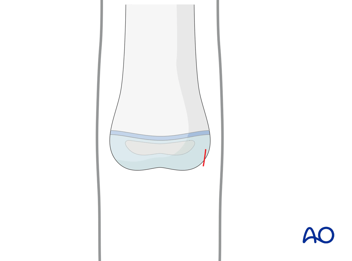
K-wire entry point
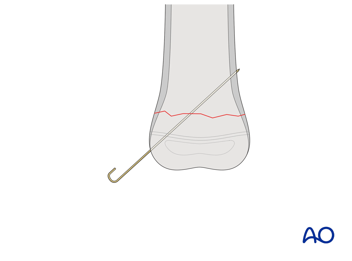
K-wires are, in most cases, inserted from the free fragment into the main fragment. This allows the K-wire to be used as a joystick for manipulating the free fragment.
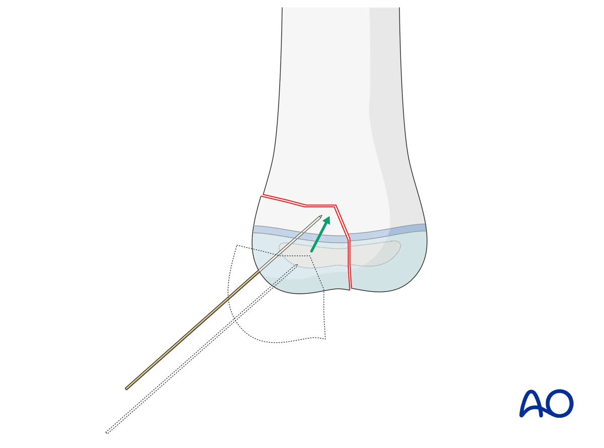
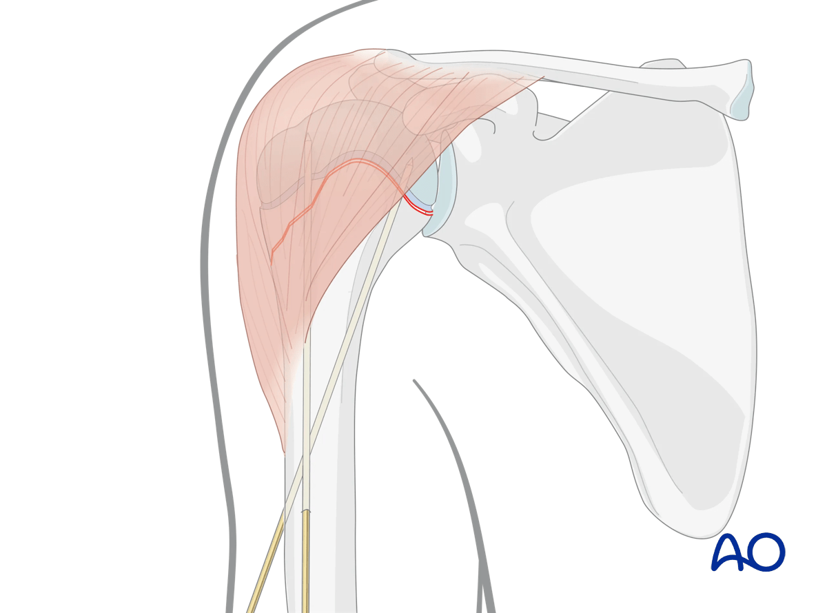
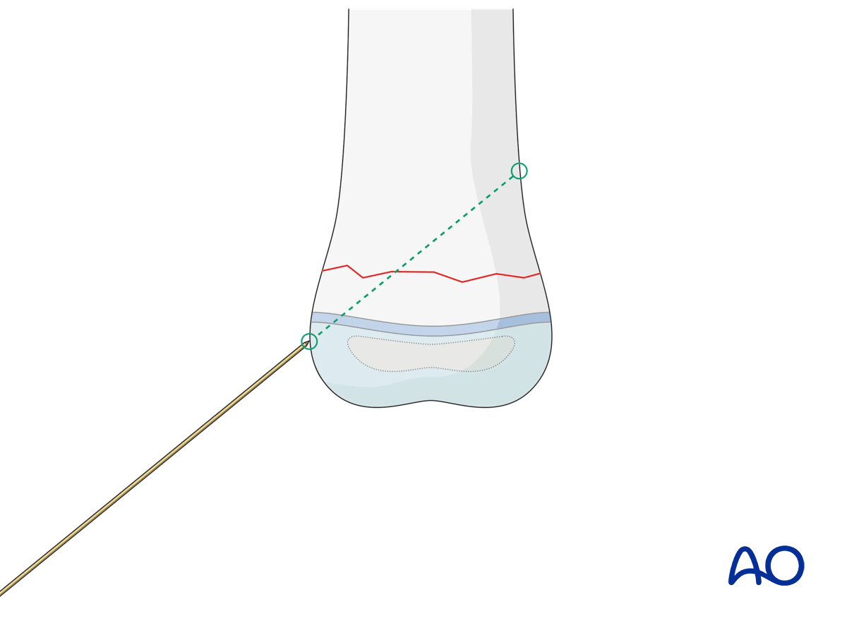
The choice of the entry point must correlate with the planned direction of the K-wire and the end fixation point in the main fragment.
Ideally, if the anatomical site permits, the K-wires should be introduced as perpendicular as possible to the fracture plane.
In certain sites, this is not achievable and mechanical stability should not be compromised by obsessive adherence to the above principle.
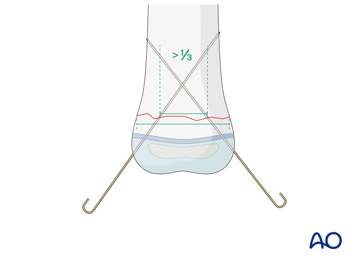
K-wire direction in transverse fractures
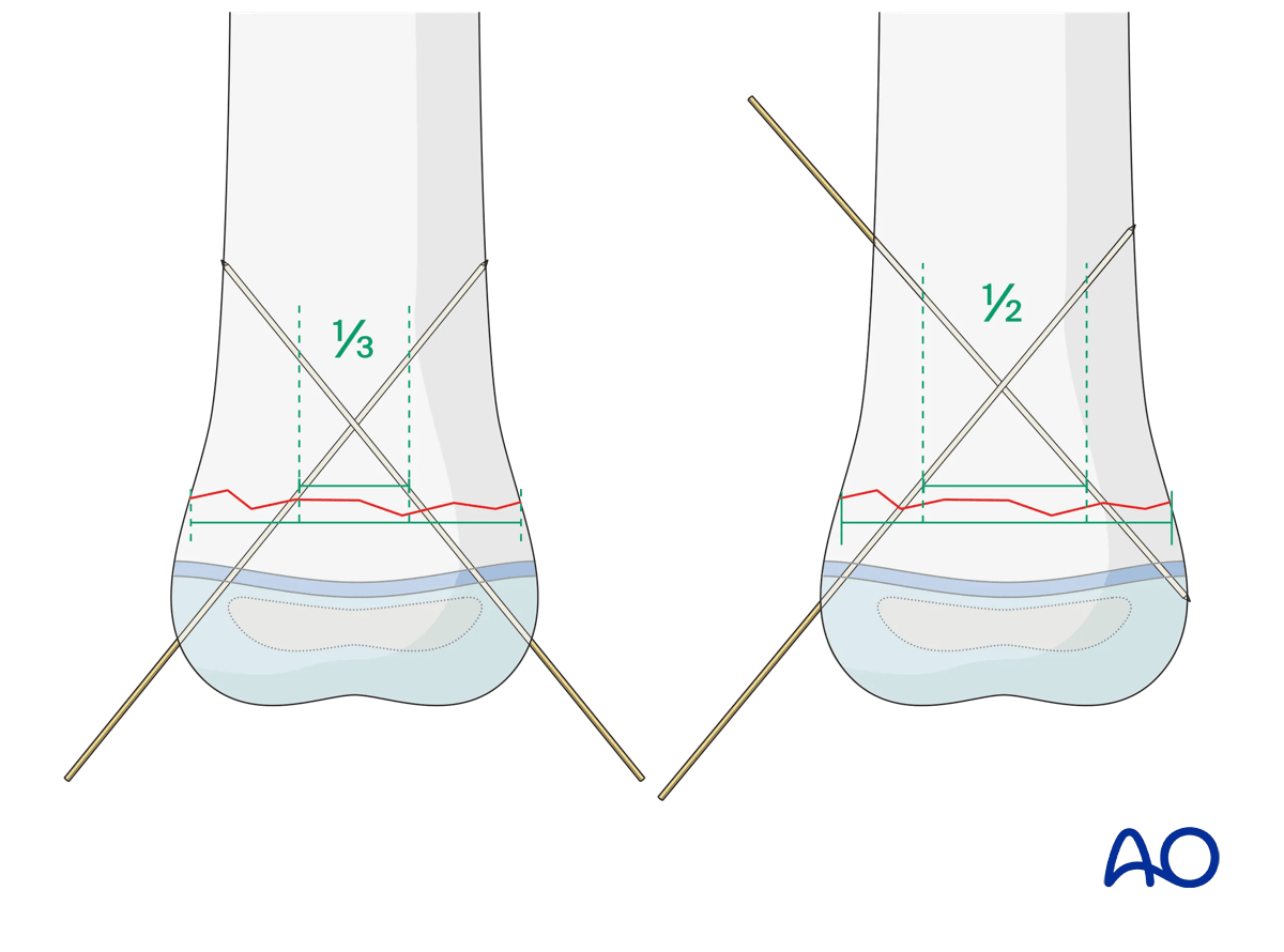
The direction of the K-wires should be chosen so that the K-wires are well separated at the fracture level.
To achieve this, the two K-wires should be spread apart >1/3 of the fracture width.
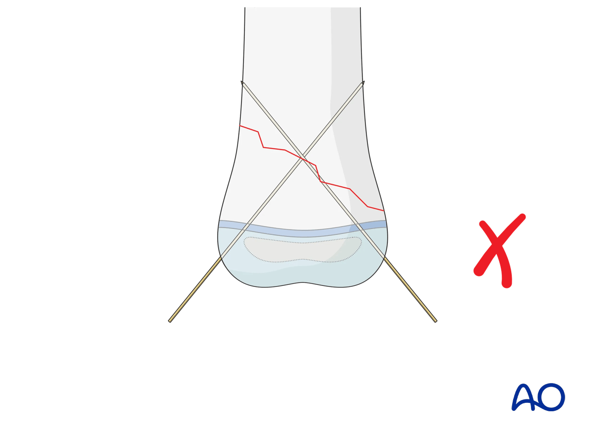
K-wire direction in oblique fractures
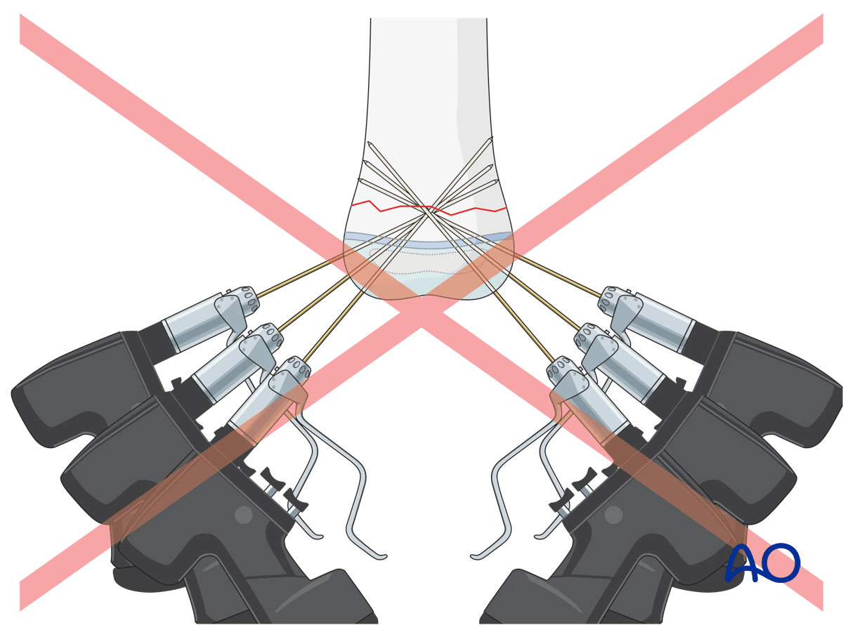
For oblique (>30°) metaphyseal fractures crossed K-wire fixation may be very difficult, or impossible, as at least one of the K-wires will run nearly parallel to the fracture line.
For oblique fractures, therefore, divergent monolateral K-wire fixation is more suitable. For this technique, one size larger K-wires should be used than for cross K-wiring.
If lateral divergent K-wire fixation is not possible, for example, due to soft tissue condition or a structure at risk, another stabilization technique should be used (eg, external fixator or plate).
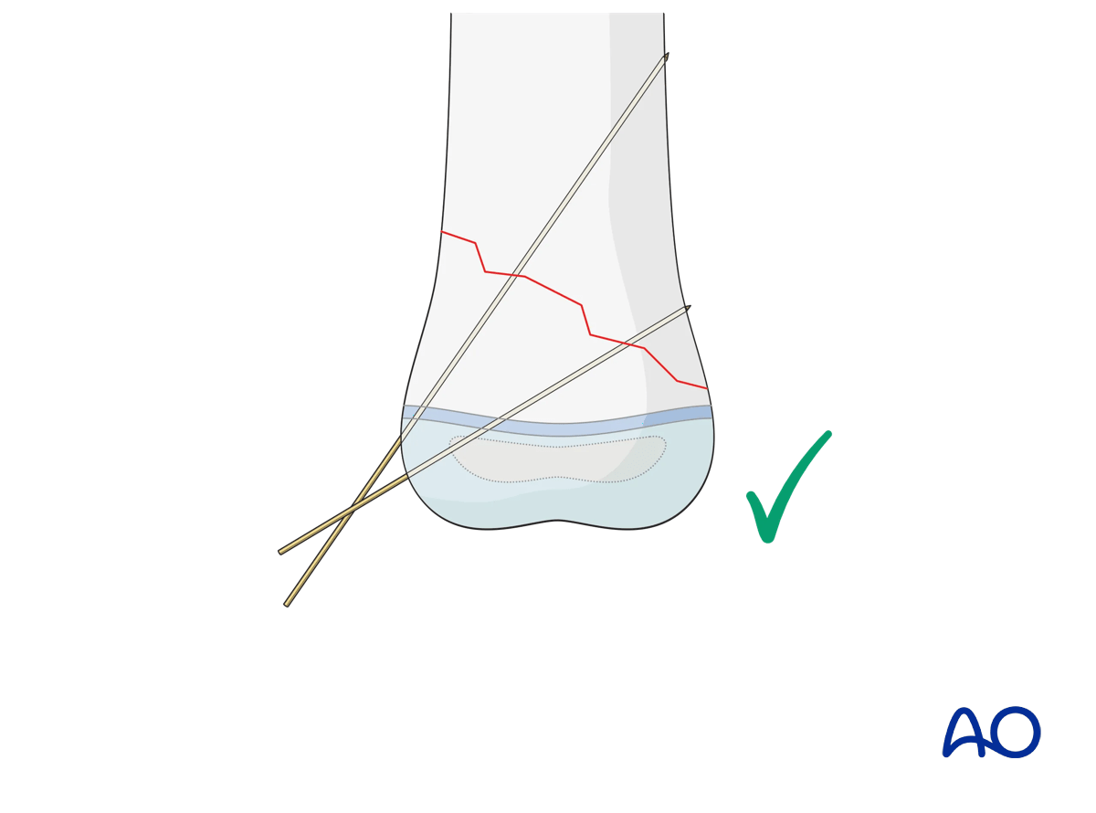
The entry points of the K-wires should be chosen so that they are as far apart as possible where they cross the fracture line. The optimal spread should be between 1/3 and 1/2 of the fracture width.
A clinical example is shown in a transverse supracondylar fracture fixed from the lateral side (to avoid injury to the ulnar nerve) with two divergent K-wires that are well spread at the fracture level.
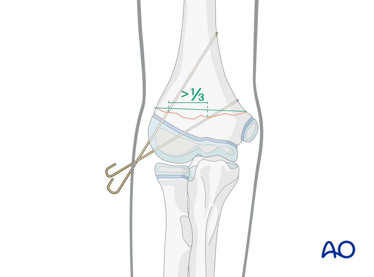
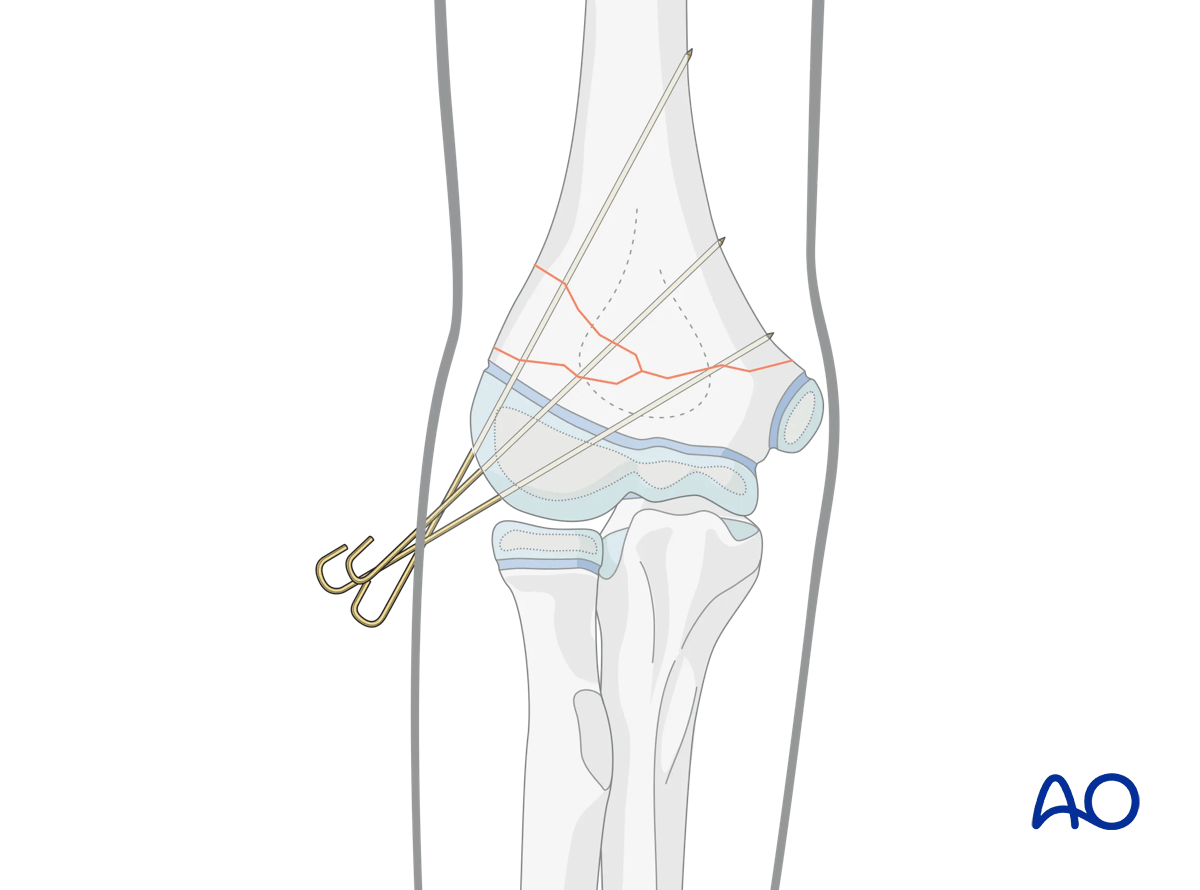
A third K-wire should be inserted if the K-wire spread is inadequate in the AP view (less than 1/3 of the bone diameter) or if the fixation is deemed insufficiently stable.
Interactive 3D animations
3D models showing crossed K-wires in a transverse fractureThe entry points of the K-wires should be chosen so that they are as far apart as possible where they cross the transverse fracture. The optimal spread should be between 1/3 and 1/2 of the fracture width (left panel). In the right panel, an inadequate spread is shown.
For oblique (>30°) metaphyseal fractures, crossed K-wire fixation (right panel) may be very difficult, or impossible, as at least one of the K-wires will run nearly parallel to the fracture line. Therefore, divergent monolateral K-wire fixation (left panel) is more suitable for these fracture types.
The pins must diverge to provide adequate spread at the fracture site on the AP view (left panel). Adequate spread is obtained if both the medial and lateral columns contain at least one pin, or if the divergence of the pins exceeds 1/3 of the width of the fracture.
If the pin spread is inadequate (right panel), the fixation is likely to be rotationally unstable. In this case, the distal fragment tends to rotate under load. For example, in a distal supracondylar fracture of the distal humerus, the distal fragment can collapse into varus, leading to a cosmetically unappealing malunion.
In clinical situations, where a well-reduced fracture is still unstable after fixing with two K-wires from one side (green), a third one should be added from the other side (blue). This should aim for the widest possible spread between the wires at the fracture line, which results in the best possible stabilization.
5. K-wire insertion
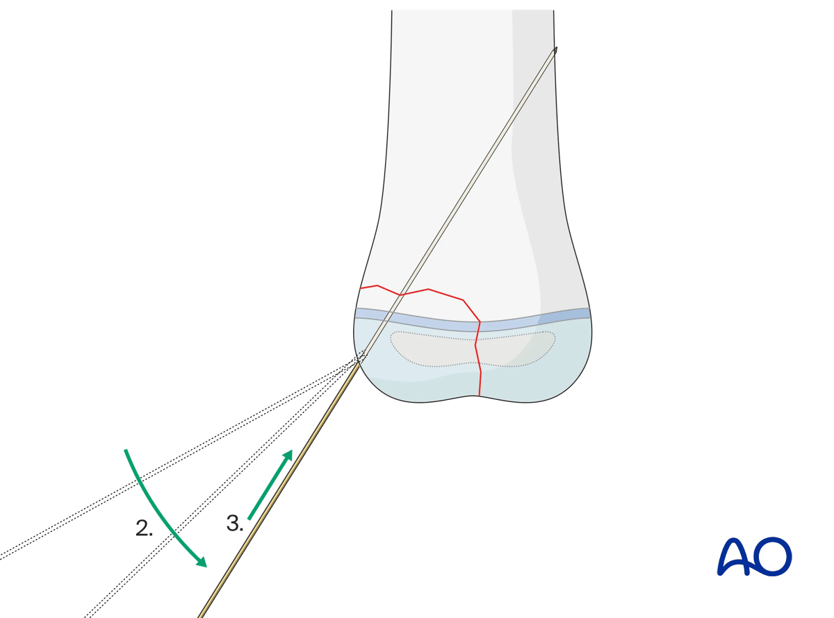
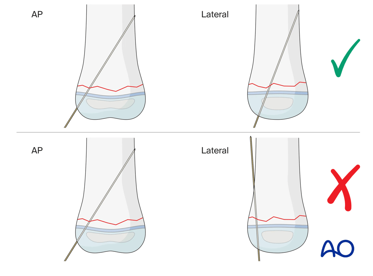
Even if the K‑wire appears correctly placed in the anterior-posterior (AP) view, always verify the medio-lateral (ML) view.
Use the rotation feature to examine both models and compare the two inserted K‑wires.
- Left panel: correct K‑wire insertion
- Right panel: incorrect K‑wire insertion
This demonstrates that relying solely on the AP view may be misleading, as a K‑wire can appear properly positioned yet prove to be malpositioned on the lateral view.
Stab incision
A small incision or a direct puncture with the K-wire is made over the planned entry point. An incision is recommended to avoid skin damage, which might cause pin-track infection.
K-wire insertion
To avoid thermal injury, especially to the physis, K-wires should be inserted by hand or using an oscillating drill.
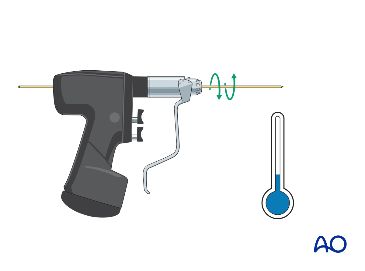
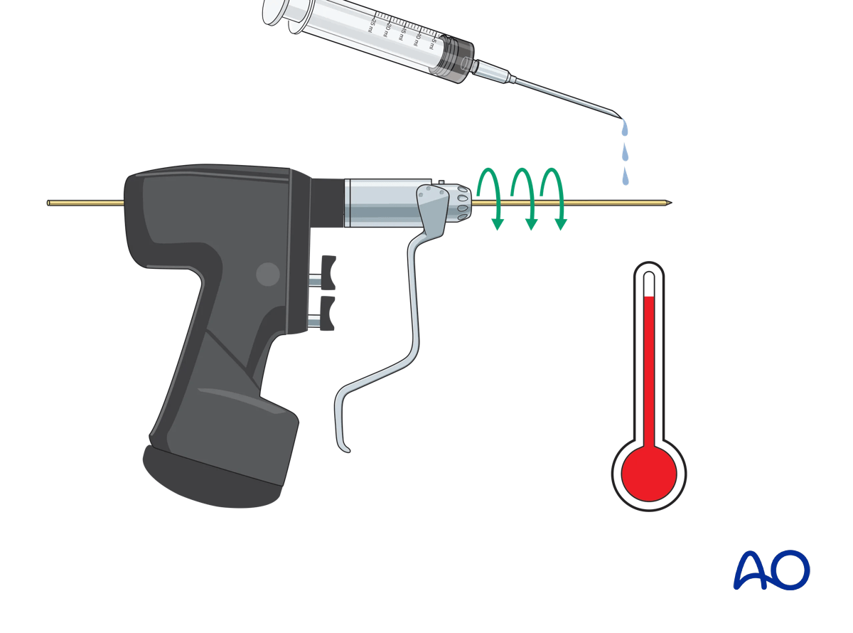
If a standard drill is used, it must be run as slowly as possible to avoid a thermal effect.
Additionally, irrigate the K-wire during drilling with a cooled irrigation fluid.
If a drill is used, the K-wire is initially inserted manually through the skin incision, onto the chosen bony entry point. While maintaining the correct position of the tip, the drill is attached to the wire.
To prevent bending of the K-wire, it can be helpful to insert the K-wire using an appropriate drill sleeve – this steadies the wire, protects the soft tissues, and ensures optimal direction.
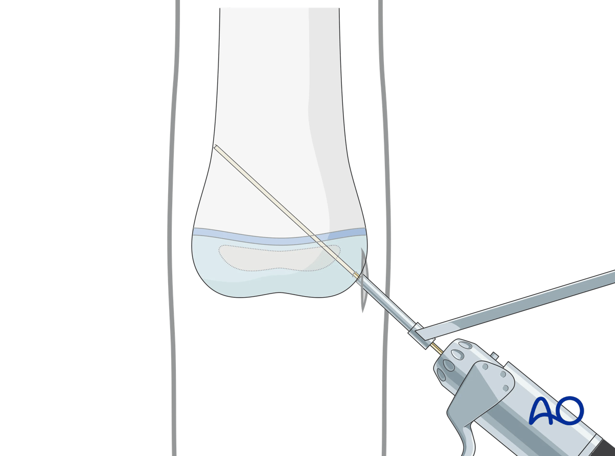
It is helpful to reduce the length of the K-wire protruding from the drill to avoid whipping of the wire and loss of trajectory.
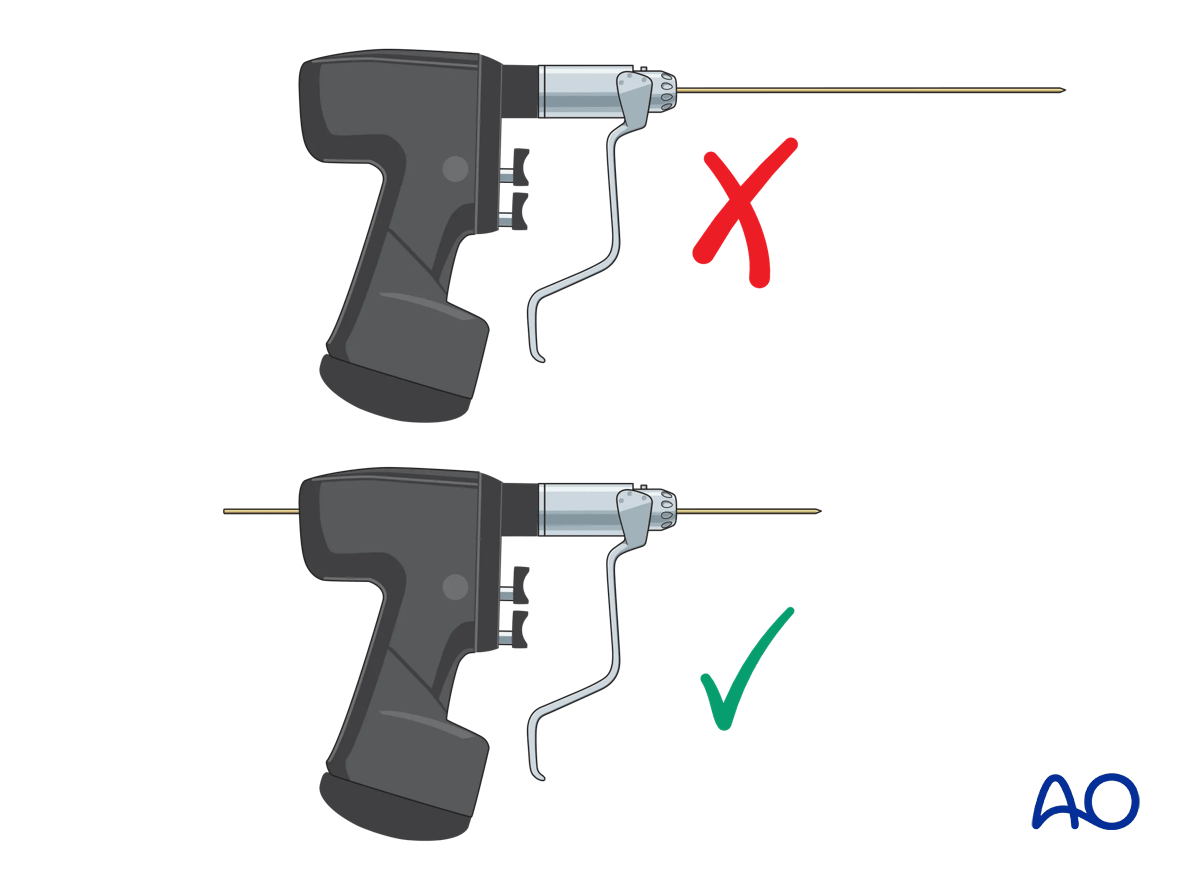
To avoid skidding, the K-wire tip should initially be held as orthogonal as possible to the bone surface until the tip of the wire has a good purchase.
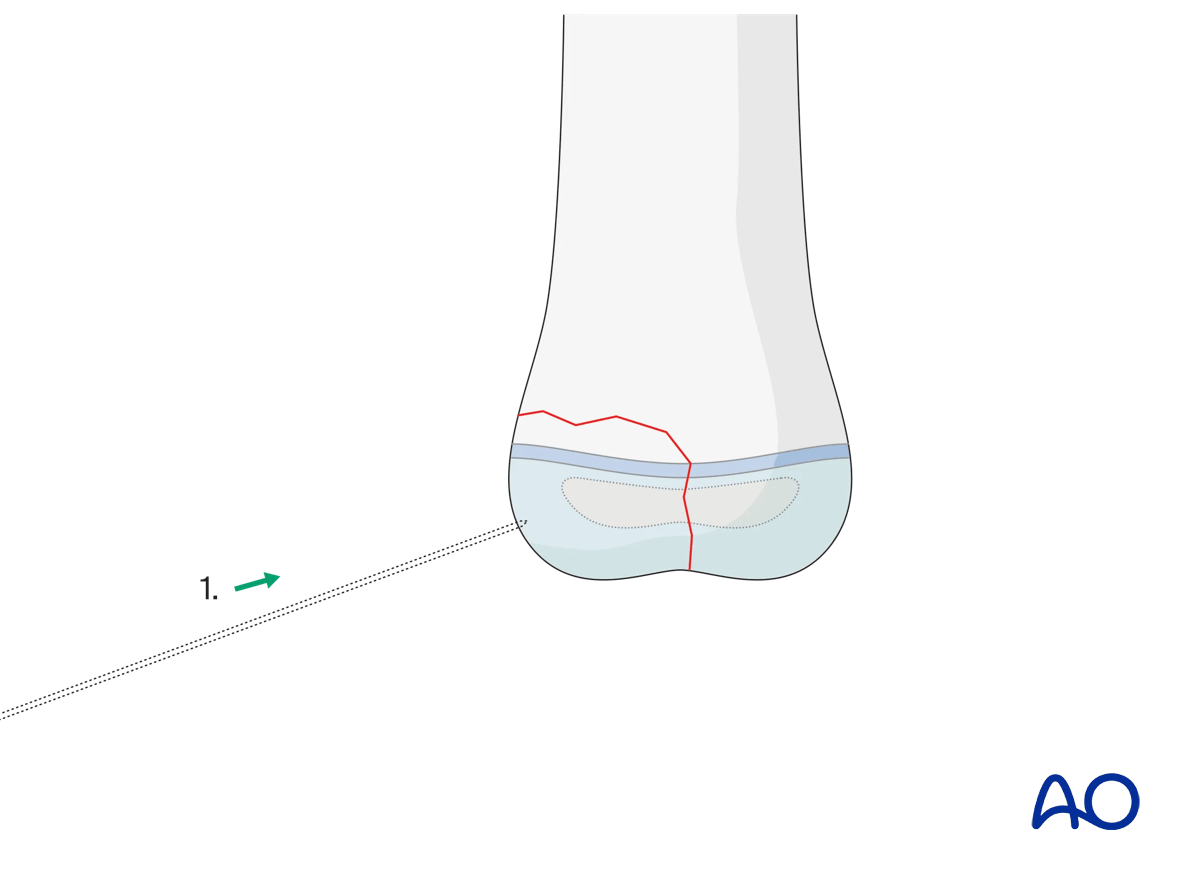
Once the tip of the K-wire has obtained a good purchase, the angulation of the K-wire should be corrected according to the planned direction of the K-wire.
The choice of the entry point must correlate with the planned direction of the K-wire and the end fixation point in the main fragment.
Ideally, if the anatomical site permits, the K-wires should be introduced as perpendicular as possible to the fracture plane.
To avoid skidding, the K-wire tip should initially be held as orthogonal as possible to the bone surface until the tip of the wire has a good purchase.
As soon as increased resistance is felt, check that the tip of the K-wire is engaged in the far cortex of the main fragment.
The tip of the K-wire should penetrate the whole depth of the far cortex, but not protrude more than 2–3 mm. This is to avoid neurovascular damage and soft tissue irritation.
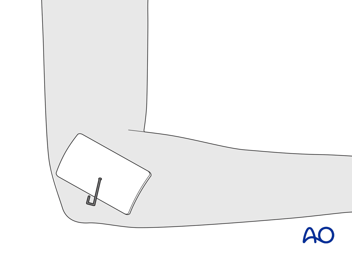
The free end of the wire is usually left protruding through the skin and is bent through 180°. A sterile dressing protects the entry wound around the wire.
No more than two attempts should be made to insert any one wire across a physis. Repeated puncture of the physis by multiple attempts to insert the wire can result in subsequent growth disturbance.
6. K-wire removal
The timing of K-wire removal is a matter of judgment by the treating surgeon, based on the age of the child, the pattern of the injury, as well as additional injuries.
Depending on the age of the child, fracture healing has reached the stage where redisplacement is highly unlikely after 3–4 weeks and the K-wires can be removed.


