Ring fixation
1. Introduction
A ring fixation system can be used to stabilize tibial shaft fractures.
This method is indicated for:
- Open and closed diaphyseal and metaphyseal fracture treatment
- Open fractures with bone loss
- Adjunct to internal fixation in complex fractures
This method is contraindicated for:
- Non-compliant patients
- Situations when there are problems with performing postoperative care
The mounting of a ring fixation system for a mid-shaft fracture is shown here.
The ring system must be planned and mounted for optimal pin and screw insertion within the prescribed safe zones.

2. Patient positioning
The patient is placed in a supine position, with the leg elevated under the knee, allowing an unobstructed approach to the lower leg.

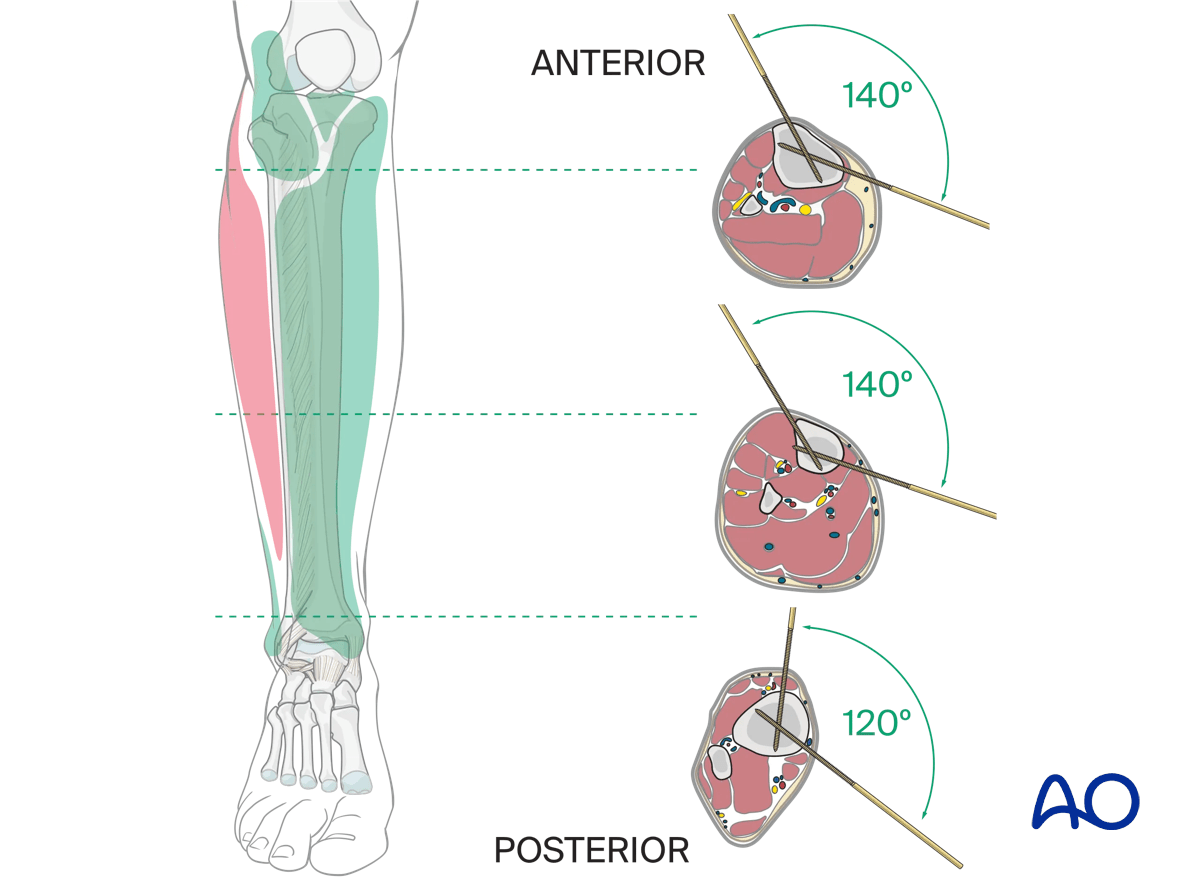
3. Surgical safe zones for pin and wire insertion
It is recommended that an inexperienced surgeon consult a cross-sectional anatomy atlas preoperatively.
Information on safe insertion of pins and wires can be found here:
4. Positioning of ring fixation blocks
Two ring fixation blocks are assembled. The length of the fixation blocks is determined by the size of the respective proximal and distal segments. The size of the rings assembled are chosen to optimally accommodate the lower leg anatomy, allowing for post-operative swelling, patient comfort, and cleaning and disinfection of the pins.
The two ring blocks are positioned on the tibia.
Positioning of the two ring blocks over the tibia separately is preferred as this allows the preassembled blocks to be passed over the leg.
The planned position of the two ring blocks aims to provide optimal stability and centralizes the fracture zone between the ring blocks.

With the two ring blocks optimally positioned, they are then connected with three or four spaced threaded rods (depending on the fixation system) and secured with nuts.

All threaded bolts are final tightened.

Teaching video
More information on the positioning of ring fixation blocks is provided in this video.
5. Insertion of proximal positioning wire
Aligning the ring fixation system parallel to the tibial axis in both AP and lateral views is optimal, in that it allows the frame to be used for bone transport if necessary.

The proximal positioning (reference) wire is inserted in the frontal plane perpendicular to the axis of the proximal tibia. It is preferable to place this wire from the lateral side to avoid injury to the peroneal nerve.
The wire is introduced under direct fluoroscopy, by pushing it through the soft tissue to the tibia.
It is recommended to use a drill in the oscillating mode until the positioning wire has perforated the contralateral cortex and is secured within the bone.
It is important to be mindful of thermal injury to the bone whenever pins and wires are inserted.
Once the wire has passed through the contralateral cortex, drilling is stopped, and the drill is removed from the wire.
A hammer is used to advance the wire in order to prevent thermal damage to the soft tissue and reduce the risk of stripping nerves, vessels, and fascia.
This also reduces postoperative pain.
The positioning wire is centered in the proximal segment and is orthogonal to the long axis of the tibia.

The ring frame is shown in the optimal position, approximately 2 cm anterior to the tibial crest.
The positioning wire is then attached to the mounting holes of the ring.
The final position of the ring on the tibia will be determined by the soft-tissue envelope. It is usually in the anterior third of the ring because of the large soft-tissue envelope posteriorly.

Wire fixation bolts are used to attach the ring assembly to the positioning wire. A counter wrench should always be used when tightening the wire to maintain the wire in the axis in which it was placed.

The wire is secured to one side of the ring. A second wire fixation bolt and nut are placed on the opposite side of the ring but are not fully tightened. The wire must be allowed to slide through the fixation bolt. This allows the wire to be tensioned.

The wire tensioner is slid over the contralateral end of the wire. The amount of tension applied depends on the clinical situation including patient weight, bone segment, ring diameter, distance of the wire from the ring, and whether a full ring or a 5/8 ring is used.
It is crucial that the ring is supported by an assistant while tension is applied.
In general, the amount of tension will vary between 50 kg and 130 kg, based on the factors described above.
The ring fixation bolt is secured, and the wire tensioner is removed.

The wires are bent into a position that avoids injury to the patient. The bending or cutting pliers are used to shorten the positioning wire and to bend it at both ends.

Alternatively, the wire can be fatigue-fractured at the end of the fixation bolt.

It is helpful for the ring frame to be parallel with the long axis of the tibia, particularly for bone transportation.

In some instances, the frame may be slightly malaligned, as illustrated. This may be corrected, if necessary (bone transport cases), by the addition of washers.
In the case that the frame is not parallel with the long axis of the tibia, washers of different thicknesses can be placed between the wire and one side of the ring to correct the alignment.
This image shows a frame that is parallel to the tibia, even though the wire was placed slightly off axis.

Inserting the proximal positioning wire first allows the frame to rotate around the pin axis and permits the correct positioning of the frame in the lateral view.

Teaching video
More information on the insertion of the proximal positioning wire is provided in this video.
6. Distal positioning wire insertion
Prior to the placement of the distal positioning wire, the frame position should ideally be parallel to the tibial axis and optimized for soft-tissue clearance.
The distal positioning wire is also placed in the frontal plane off the most distal ring. Again, safe zones need to be considered. Placing the wire from lateral to medial, through or just anterior to the fibula, is often convenient.
The basic steps of this wire placement are identical to the proximal positioning wire.

The AP and lateral views show that the proximal and distal positioning wires have achieved good alignment of the frame and bone, and appropriate soft-tissue clearance.
In some cases, the proximal and distal fragments can be translated on their reference wires to aid in axial alignment.
The anatomy of the patient and the fracture characteristics determine the stability requirements of the frame. In general, each bone segment requires a minimum of three, and preferably four fixation elements (wires or Schanz screws) spaced across the fixation block for stability.

7. Options for Schanz screw placement
Schanz pins in the tibia are generally placed from the medial side (anteromedially, direct medial, or posteromedial). Pin divergence within the safe zone helps to optimize biomechanical stability of the frame.
Predrilling prior to placement of Schanz screws is recommended in order to minimize thermal necrosis of the bone.
In general, 5 mm or 6 mm blunt-tip Schanz screws are used in the tibia of adult patients. Schanz screws are available in uncoated, and hydroxyapatite (HA) coated versions. HA coated pins should be considered in clinical scenarios in which the frame is expected to be on for an extended period of time as they have been shown to decrease infection and loosening rates.
Predrilling is performed with the recommended drill size and drill sleeves, with attention to water cooling. Schanz screws should be manually inserted.
The exact method for mounting a Schanz screw will depend on the ring fixation system being used. In general, Schanz screws can be mounted directly on a ring, at a fixed distance off a ring, and angulated off a ring.
When angulating a pin off a ring 30° from the ring axis is optimal.
One type of Schanz screw mounting method is shown here.

Schanz screw mounting with multiparallel pin clamp
The eye bolt fits into the square hole and the groove of the multiparallel pin mount in only one direction.

The steps for Schanz screw insertion are as follows:
Once the chosen location for the Schanz screw is determined, the assembled eye bolt and the selected multiparallel pin clamp are secured to the ring.

The triple drill sleeve is inserted through the eye bolt. To do this the nut holding the eye bolt needs to be loosened.
In the diaphysis it is imperative that Schanz screws be bicortical.

A skin incision is made at the skin contact point.

The soft tissue is spread down to bone using a hemostat. The triple sleeve is then passed to the bone surface. Fluoroscopic confirmation of position is recommended to avoid unicortical pin placement.

Then the inner trocar is removed, and the drill is introduced and drilled across both cortices. Attention is paid to irrigation and slow drilling in order to avoid thermal necrosis. The desired thread length of the Schanz pin is chosen from the calibrated drill.
The drill and the innermost trocar are removed and the Schanz screw is placed manually.
The outer trocar is then removed and the nut securing the eye bolt is tightened. The nut securing the multiparallel pin clamp should also be tightened. This can be accomplished with two wrenches, or alternatively the pin can be held manually and used to create counter-torque during these maneuvers.


Placement of additional Schanz screws
Additional Schanz screws should be placed respecting the following considerations:
- Anatomic safe zones
- Multi-planar placement to optimize biomechanics
- Three to four fixation elements per segment

When placing an angled pin off a ring, optimal biomechanics are achieved when the angle is between 25° and 30°.

8. Completion of frame assembly
The number of connecting rods used depends on the specific external fixation system. If connecting elements are 6 mm in diameter it is recommended to use four rods between all rings. If 8 mm in diameter then three rods are sufficient.
This illustration shows that appropriate stability has been achieved.
The proximal and distal segments of the tibia have each been secured to the ring frame by one wire and two Schanz screws widely separated. In situations of poor bone quality, or very near the ends of the bone, additional pins and wires should be considered to create appropriate stability.
All threaded connections should be checked and tightened.
This illustration shows an 8 mm external fixation system.
9. Olive reduction wires
Teaching video
Olive reduction wires can be used for fixation and manipulation of fracture fragments within the ring. Further information on this technique can be found in this video.
10. Case example
The clinical case shows a 15-year-old girl who sustained a closed comminuted tibial fracture from a skiing injury, AO classification 42C2.

The initial treatment was an open reduction and plate osteosynthesis.
The patient developed severe deep infection at six weeks postoperative.

At the second treatment the plate was removed, and the fracture site was debrided. A two-fixation block ring system was applied.

Six weeks after placement of the ring fixator good healing was observed, and the ring fixator was removed (image on left). Radiological control after one year shows good fracture healing (image on right).

11. Aftercare
Pin site care
Proper pin insertionTo prevent postoperative complications, pin insertion technique is as important as the pin care protocol:
- Correct placement of pins and wires (see safe zones) avoiding ligaments, nerves, and tendons, eg, anterior tibial tendon
- Correct insertion of pins (eg, trajectory, depth) avoiding heat necrosis
- Extending skin incisions to release soft-tissue tension around the pin insertion (see inspection and treatment of skin incisions)
- Creation of a mechanically stable frame will minimize pin-site motion
These images show the release of a pin to minimize skin tension. A releasing incision is made with a scalpel, as shown. After release, the left and right sides are sutured to create a tension-free closure.

Various aftercare protocols to prevent pin tract infection have been established by experts worldwide. Therefore, no standard protocol for pin site care can be stated here. Nevertheless, the following points are recommended:
- Relative motion between pin and skin should be minimized as a general rule. This is particularly important in areas of thick tissue or significant soft-tissue movement.
- A compressive dressing that limits skin motion is useful, initially after frame placement, and continued for any pin exhibiting ongoing drainage.
- A daily shower with antibacterial soap is very useful after surgical incisions have healed.
- Pin insertion sites should be kept clean. Any crusts or exudates should be removed. The pins may be cleaned with saline and/or disinfectant solution/alcohol. The frequency of cleaning depends on the circumstances and varies from daily to weekly but should be done in moderation.
- Dressings are not usually necessary once pin drainage has ceased.
- Pin insertion sites need not be protected for showering or bathing with clean water.
- The patient or the care-giver should learn and apply the cleaning routine.
- Oral antibiotics are reserved for pin site infections.
These images provide examples of compressive dressings.

In case of pin/wire loosening or pin tract infection, the following steps need to be taken:
- Rest and elevate limb
- Moist saline compress
- Oral antibiotic
- Wrap pin to control skin/pin motion
- Release any skin tension
For recalcitrant pin-site problems consider:
- Culture drainage and switch to organism-specific antibiotics
- IV antibiotics
- Checking x-ray for lucency
- Removal or exchange of pin
Mobilization
In most cases of ring fixation, stability is sufficient to allow weight bearing as tolerated. Exceptions to this include intraarticular fractures or significant soft tissue concerns. In these cases, weight bearing should be delayed until healing of the intraarticular fracture (8–12 weeks).
Joint range of motion should begin both actively and passively as soon as soft tissues allow. In the lower extremity the development of a knee flexion contraction and/or ankle equinus are significant concerns and should be monitored at every clinic visit.
Attention should be paid to DVT prophylaxis which will be determined on the specifics of the clinical scenario.
The two images show active and passive range of motion of the ankle in the frame.

The image shows one method of static splinting of the ankle in the neutral position.

Patients should be taught terminal knee extension exercises. These images demonstrate terminal knee extension exercises in the frame.

Follow up
The patient should be seen at two weeks after surgery for suture removal, and then every 2–4 weeks with radiographs to monitor fracture healing. At every clinic visit the frame should be inspected for pin problems, and frame loosening. The patient should be observed ambulating, and range of motion of adjacent joints should be examined.

Frame removal
The timing of frame removal is determined by a combination of the clinical scenario and radiographic evaluation of the fracture. In lower extremity applications the patient should be comfortably weight bearing in the frame as supporting evidence of fracture healing. Fracture healing should be visualized radiographically on three cortices. The clinical appearance of the pins is usually quite good at this point with minimal to no pin drainage. This observation confirms that the frame is offloaded because of healing of the bone.
The method of frame removal depends on the patient and the type of pins used. When hydroxyapatite (HA) coated pins have been used, frame removal will require sedation/anesthesia. In selected cases with non-HA coated pins, frame removal can be performed in the clinic.
Post frame removal care
Some form of external stabilization (fracture boot or cast) is recommended in the early period after frame removal (4–6 weeks). Pin sites will generally require dressing changes for 3–4 days. Weight bearing as tolerated is usually allowed immediately following frame removal. Showering should be allowed once all pin sites are dry.


