Nailing without image intensification
1. Principles
Nailing
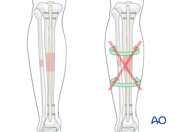
Intramedullary (IM) nailing is the first treatment choice for most tibial shaft fractures because it offers durable fixation with sufficient stability for weight bearing. IM nailing has been proven successful in many clinical settings.
Nail fixation provides relative stability and promotes indirect healing with callus.
With moderate soft-tissue compromise, nailing is often a viable option while plating may not be possible.
Proximal and distal locking screws improve IM nail fixation by providing rotational and axial stability and permitting nailing of more proximal and distal fractures.
More information is provided here:
Nailing without image intensification
Image intensification is routine for IM nailing, when available. Tibial nailing can be done without image guidance, but only with modified techniques and implants. If performed, attention must be paid to the following:
- Choosing a proper entry site
- Reducing the fracture
- Passing the nail across the fracture site
- Ensuring proper nail length
- Inserting distal locking screws
Preoperative planning, exposure of the entry site, open reduction of the fracture, and special distal locking guides are valuable aids.
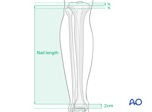
Determining nail length
Nail length must be determined preoperatively. If the contralateral tibia is intact, a tape measure or x-ray techniques can be used. The proper length nail must be available, and an assortment of nails may be helpful if measurement errors occur. Too long a nail may distract the fracture or be too prominent. Too short a nail may compromise fixation.
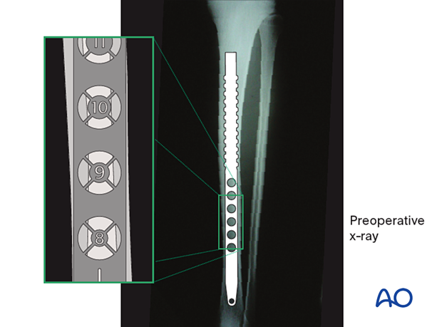
Determining nail diameter
The nail diameter must fit through the narrowest part of the tibial shaft, which may be increased by intramedullary reaming. Diameter gauges may be used with both AP and lateral radiographs, but magnification errors might exist. The curvature of the tibia and the nail may differ, so that a nail of the measured diameter may not be insertable. Reamers, or smaller nails, may be required.
2. Reduction
Reduction difficulties
Delayed reductionIf nailing will be delayed, a temporary external fixator can maintain distraction, thus aiding reduction. If the fracture consolidates with shortening, it will be difficult to achieve closed reduction, particularly after 10–15 days. An initial attempt at closed reduction may be tried, but if unsuccessful, proceed directly to open reduction.
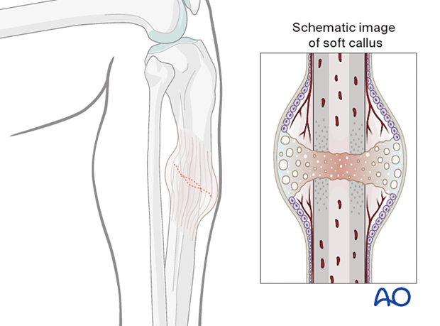
Initial reduction for guide wire
The fracture must be reduced to permit passage of the guide wire. A slight bend just above the ball tip may make it easier to pass the wire through the fracture zone. Reduction of the fracture to allow guide wire insertion may be possible with traction and manual manipulation. If not, open reduction will be required.
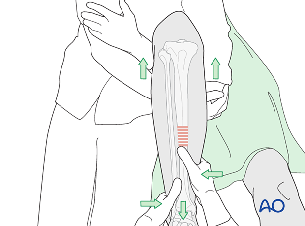
Manual traction
Usually, two people are required to perform manual traction. One person holds the leg and the other exerts traction by pulling the leg and controlling the reduction by palpating the tibial crest and the anteromedial surface.
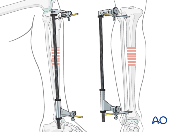
Using a distractor
A large distractor is usually placed in a coronal plane. It lies posterior to the tibia, either laterally or medially so as not to obstruct the placement of locking screws.
The proximal Schanz screw must be sufficiently posterior to avoid blocking the nail. Place it parallel to the tibial plateau to aid proximal fracture alignment. The distractor’s distal pin should be outside the intended nail location, posteriorly in the distal tibia, or in the talus.
An external fixator is an alternative to the distractor. Schanz screw placements are the same.
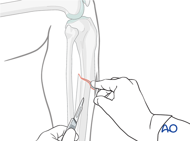
Open reduction
IncisionLocate the fracture by palpation. Make a small incision over the fracture. Extend the incision sufficiently to access the fracture.
Free up one side of the fracture site at a time with minimal dissection.
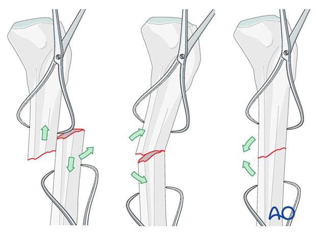
If the fracture is transverse, it may be reduced with manipulation using clamps on the bone ends. This often requires excessive exposure. Percutaneous Schanz screws are less invasive. The technique is as follows:
- Free up the ends of both fracture fragments.
- Align the crest of both fragments. This will assure proper rotation.
- Flex the fracture to 45°, or enough to place one fragment onto the other.
- Approximate the cortical edges, and gradually straighten the fracture, which compresses the fracture site.
- Check rotation.
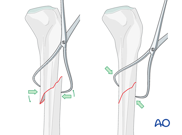
If the fracture is oblique, a bone clamp can be used to compress the fractures, which may restore appropriate length.
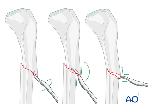
Alternatively, a Hohmann retractor can be used for reduction by placing it between the fracture fragments and prying them apart. It is important to hold this position for at least 30 seconds in order to stretch the tissues.
It is very important to maintain the reduction while the nail is inserted. This often requires an assistant, or temporary use of adistractor, external fixator, or plate with unicortical screws.
3. Reaming
Introduction
Cannulated reamers with flexible shafts are used over a ball-tipped guide wire that is placed through the reduced fracture. Noncannulated reamers are another option, and are used without a guide wire. Whichever technique is used, the fracture must be kept reduced during reaming.
Guide wire placement
Once the guide wire is inserted all the way to the tibial plafond, significant bony resistance is usually felt, except when severe osteoporosis is present.
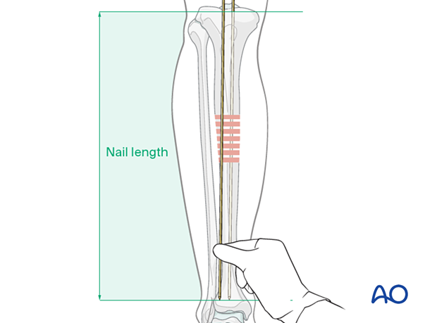
The length of the medullary canal can be checked by using a second guide wire (of equal length), held adjacent to the intramedullary wire, and with its tip placed in the entry site. The length of the second guide wire protruding above the first guide wire is equivalent to the length of the guide wire within the medullary canal.
This confirms the appropriate nail length.
Power reamers
Start with the smallest reamer bit and serially enlarge the medullary canal with reamers of increasing diameter until mechanical contact is made over an approximately 6 cm segment of the medullary canal isthmus. The appropriate nail diameter, estimated from preoperative x-rays, should be large enough for strength and durability, and usually approximately 1.5 mm smaller than the final reamer bit.
It is important that the nail fits easily through the medullary canal. If it does not advance readily, it should be withdrawn and additional reaming carried out.
Hand reamers (non-cannulated)
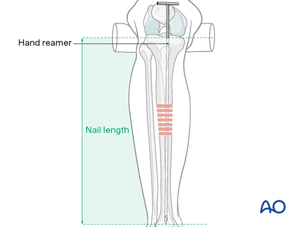
With the fracture reduced, the medullary canal is enlarged by serially passing hand reamers of increasing diameter. Once you feel loose bone contact of the reamer within the intramedullary canal for approximately 6 cm, the reamer diameter usually indicates an appropriate nail diameter. Advance the reamer until it lies at the desired location for the tip of the nail, usually just above the subchondral bone of the distal tibia.
The correct length for the nail is indicated by the length of the reamer inserted into the bone if the fracture is not distracted.
It is important that the nail fits easily through the medullary canal, and if it does not advance readily, it should be withdrawn and additional reaming carried out.
4. Nail assembly and insertion
For nail assembly, please refer to the technique guide of the implant system you have chosen.
5. Nail insertion
Insert nail
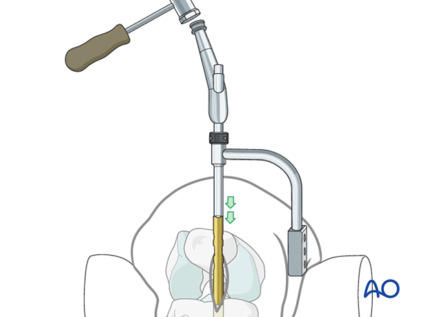
Insert the IM nail into the hole in the proximal tibia. Be sure that the nail is properly placed in the entry site and is also aimed towards the medullary canal.
Protect the skin with retractors, as necessary.
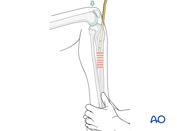
Remember that the knee must be sufficiently flexed (>90 degrees) to allow proper nail alignment.
Advance the nail to the fracture site, making sure that it follows the desired path.
Alignment during nail insertion
The fracture must be aligned satisfactorily for nailing to avoid comminution as the nail is driven through the fracture zone. Merely positioning the distal segment so that the tip of the nail enters it, and allowing the nail to align the tibial axis works well in the mid-diaphyseal region. Confirm correct rotation as the nail crosses the fracture. Length must also be adjusted as the nail is inserted to avoid either shortening or distraction of the fracture.
While fractures in the narrow portion of the medullary canal usually align well with nail insertion, proximal and distal fractures require special efforts from the surgeon to avoid angulation.
Unless a tibial fracture is quite stable, it must be supported in some way while the nail is inserted. Manual distraction is possible, but often awkward. A fracture table, or devices such as a large bone distractor, or external fixator, are valuable aids. Initial distraction helps align the fracture site. As the nail is advanced distally, resistance must be provided to maintain bone contact at the fracture. As the nail is advanced, ensure correct rotational alignment of the fracture fragments.
Advance nail past fracture site
Now fully insert the nail.
After the nail passes through the fracture site, stabilize the foot on the OR table to maintain reduction without distraction as the nail is advanced.
6. Insertion of proximal and distal interlocking screws
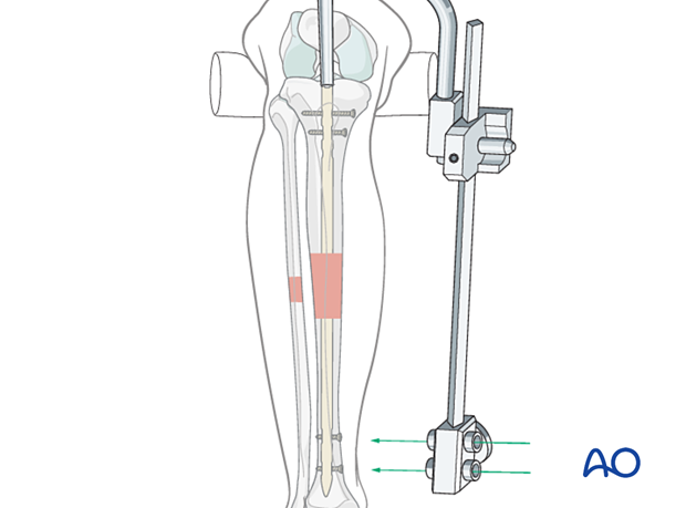
Use the nail’s targeting arm to insert interlocking screws. Please refer to the nail technique guide for further details.
7. Aftercare
Perioperative antibiotics may be discontinued before 24 hours.
Attention is given to:
- Pain control
- Mobilization without early weight bearing
- Leg elevation in the presence of swelling
- Thromboembolic prophylaxis
- Early recognition of complications
Soft-tissue protection
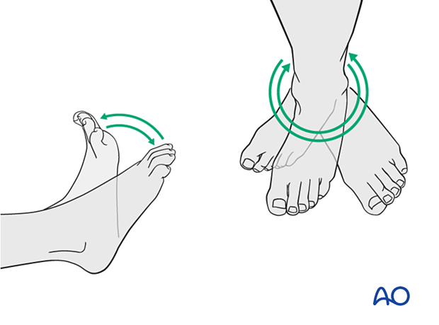
A brief period of splintage may be beneficial for protection of the soft tissues but should last no longer than 1–2 weeks. Thereafter, mobilization of the ankle and subtalar joints should be encouraged.
Mobilization
Active, active assisted, and passive motion of all joints (hip, knee, ankle, toes) may begin as soon as the patient is comfortable. Attempt to preserve passive dorsiflexion range of motion.
Weight bearing
For fractures treated with plating techniques, limited weight bearing (15 kg maximum), with crutches, may begin as tolerated, but full weight bearing should be avoided until fracture healing is more advanced (8–12 weeks).
For fractures treated with intramedullary nailing, weight bearing as tolerated, with crutches, may begin immediately.
Follow-up
Follow-up is recommended after 2, 6, and 12 weeks and every 6–12 weeks thereafter until radiographic healing and function are established. Weight bearing can be progressed after 6–8 weeks when x-rays have indicated that the fracture has shown signs of progressive healing.
Implant removal
Implant removal may be necessary in cases of soft-tissue irritation caused by the implants. The best time for implant removal is after complete bone remodeling, usually at least 12 months after surgery. This is to reduce the risk of refracture.
