Intraoperative imaging of the proximal tibia
1. Introduction
Fluoroscopic visualization of anatomical fracture reduction and correct implant placement for the proximal tibia can be significantly facilitated using the following views:
Standard views:
- AP view
- Lateral view
- AP with 10° cephalic tilt view
- AP view with 45° external and internal rotation
- Modified lateral views to assess the medial and lateral plateau
The following represents ideal imaging with the patient placed in the supine position. The relation between the proximal tibia and the beam remains the same for patients in all other positions.
The orientation of the C-arm has to be adjusted accordingly.
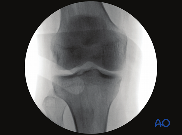
2. AP view of the proximal tibia
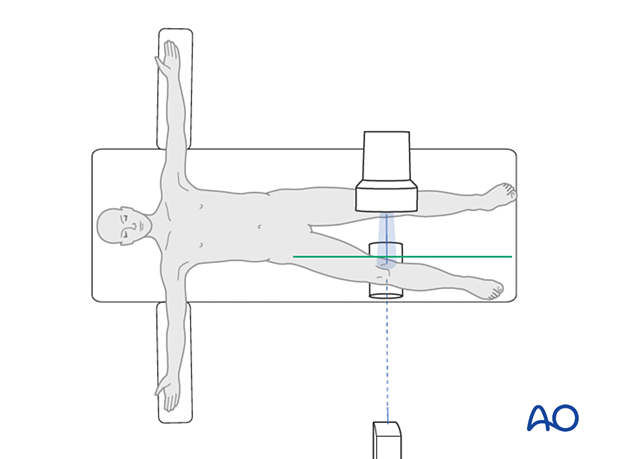
Positioning for optimal view
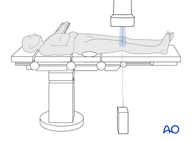
To obtain the optimal AP view of the proximal tibia:
- the leg is placed in full extension and neutral rotation.
- the beam is placed perpendicular to the axis of the tibia.
AP images obtained with the knee in 30° flexion will not be very different from those recorded with the leg in full extension.
With the knee in 90° flexion, an AP view cannot be obtained.
Verification of optimal view
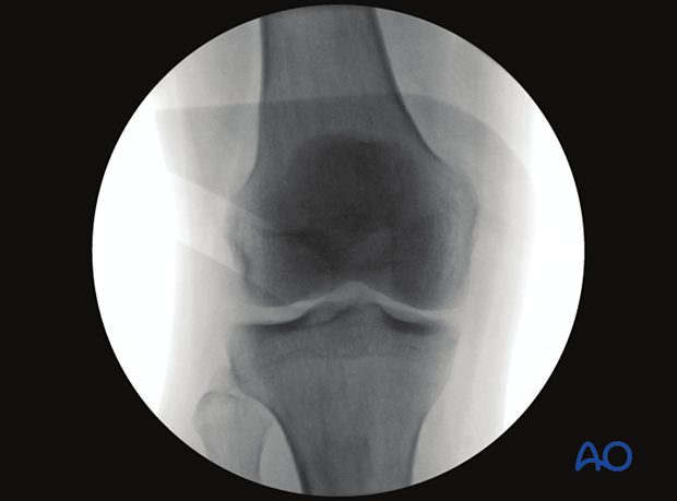
The optimal AP view of the proximal tibia is obtained when:
- the patellar apex is centered over the femoral notch.
- there is 1/4 to 1/3 of the fibular head overlapping the lateral edge of the proximal tibia.
- the beam is centered on the tibial plateau.
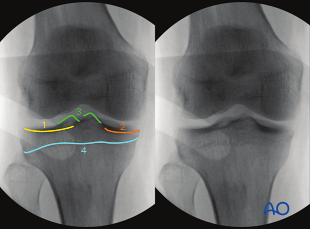
Anatomical landmarks and lines
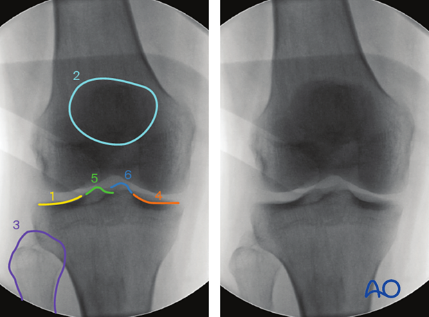
The following lines and landmarks can be observed in the AP view of the proximal tibia:
- Lateral tibial plateau
- Patella
- Fibula head
- Medial tibial plateau
- Lateral tibial spine
- Medial tibial spine
What can be observed
This view is particularly useful to identify:
- Malreduction of Intraarticular fractures (articular steps)
- Intraarticular hardware
- Opening of the joint space under varus or valgus stress (indication of collateral ligament injury)
- Avulsions fractures of the tibial spine (indication of cruciate ligament injury)
The correct angle between the joint line and the tibial axis (85-90°)
Images of the contralateral side may be beneficial as a reference.
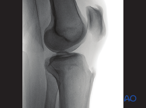
3. Lateral view of the proximal tibia
Positioning for optimal view
To obtain the optimal lateral view of the distal femur:
- the leg is flexed to elevate the knee.
- the leg is placed in neutral rotation.
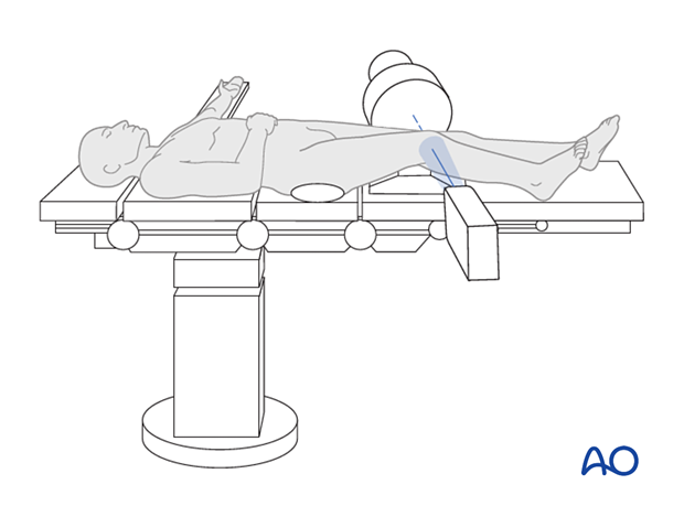
Verification of optimal view
The optimal lateral view to the proximal tibia is obtained when:
- the beam is placed parallel to the tibial joint plane (or perpendicular to the tibial axis).
- the femoral condyles are superimposed in anterior, distal and posterior aspects
- the femoral condyles are centered on the screen
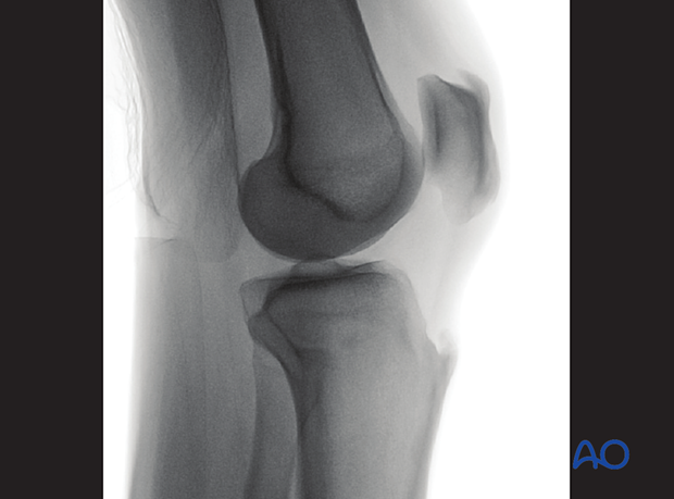
Anatomical landmarks and lines
The following lines and landmarks are seen in the lateral view of the proximal tibia:
- Lateral tibial plateau (convex line)
- Medial tibial plateau (concave line)
- Tibial spine
- Tibial tuberosity
- Epiphyseal scar
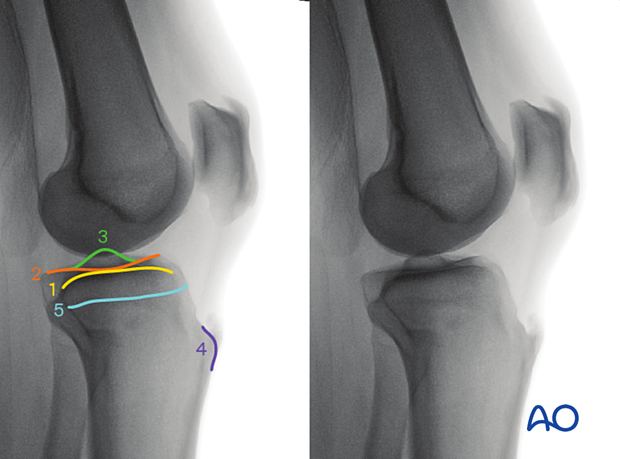
What can be observed
The lateral view of the proximal tibia is particularly useful to identify:
- Malreduction of the medial and lateral plateau
- Malreduction of the tibial spine
- Anterior or posterior subluxation of the tibial plateau relative to the femur (indicative of cruciate ligament injury)
- Intraarticular hardware
4. AP view of the proximal tibia with 10° cephalic tilt
Positioning for optimal view
To obtain the optimal view, start from the optimal AP view and tilt the C-arm caudally until the AP view of the true tibial joint line is obtained (ca 10°).
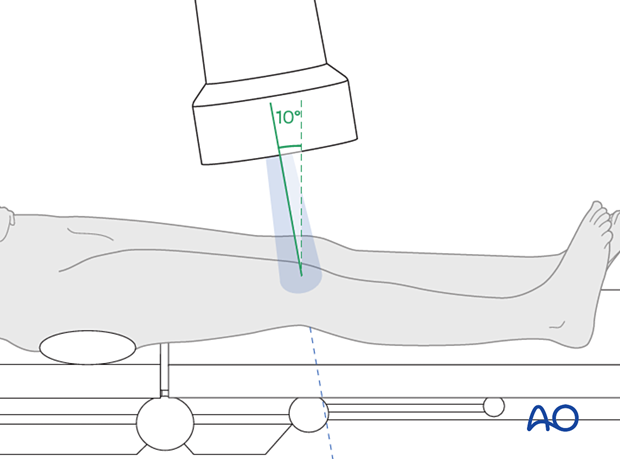
Verification of optimal view
The optimal view of the true tibial joint line is achieved when:
- the tibia joint line is centered on the screen
- The medial and lateral joint lines appears as one thick line.
Anatomical landmarks and lines
The following lines and landmarks can be seen:
- Lateral tibial plateau (convex line)
- Medial tibial plateau (concave line)
- Medial and lateral tibial spine
- Epiphyseal scar
What can be observed
This view is particularly useful to identify:
- Joint malreduction
- Intraarticular hardware
The correct angle between the tibial joint line and the tibial axis (85-90°).
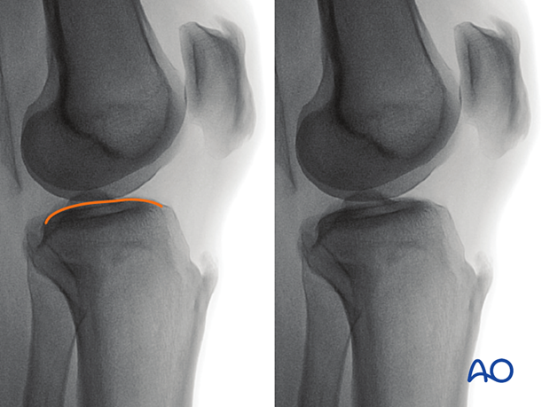
5. Modified lateral view to evaluate the lateral plateau
Positioning for optimal view
To obtain the optimal view for evaluating the lateral tibial plateau, start from the perfect lateral view and abduct the leg approximately 10-20°.
Verification of optimal view
The optimal lateral view to assess the lateral tibial plateau is obtained when:
- the contour of the convex lateral plateau is seen in the joint space cranially to the concave medial plateau.
- the lateral tibial plateau is centered on the screen.
Anatomical lines and landmarks
The following lines and landmarks can be observed:
- Lateral tibial plateau
What can be observed
This view is particularly useful to identify:
- Incongruency of the joint line
- Joint penetration of hardware
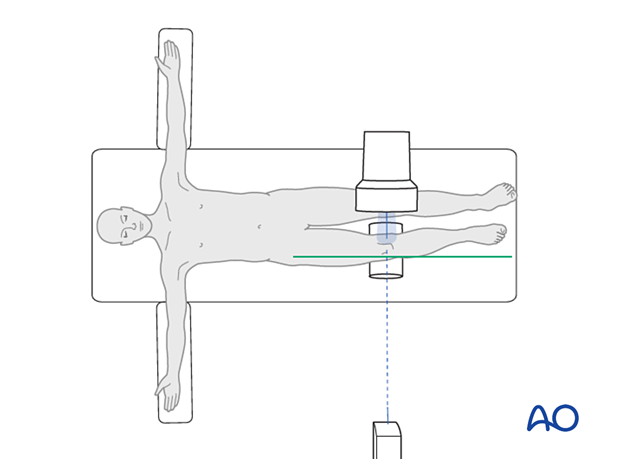
6. Modified lateral view to evaluate the medial plateau
Positioning for optimal view
To obtain the optimal view for evaluating the medial tibial plateau, start from the perfect lateral view and adduct the leg approximately 10-20°.
Verification of optimal view
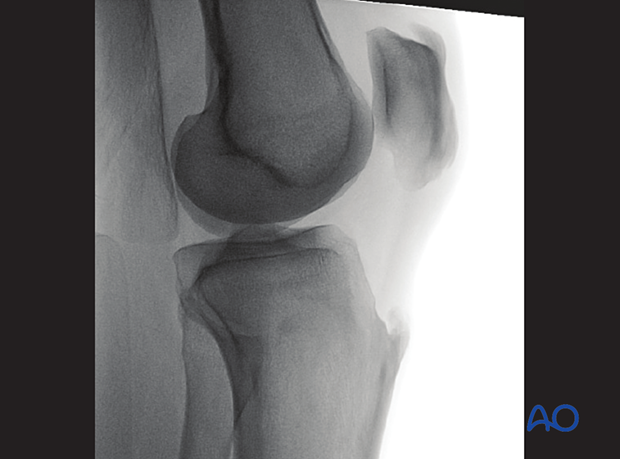
The optimal lateral view to assess the medial tibial plateau is obtained when:
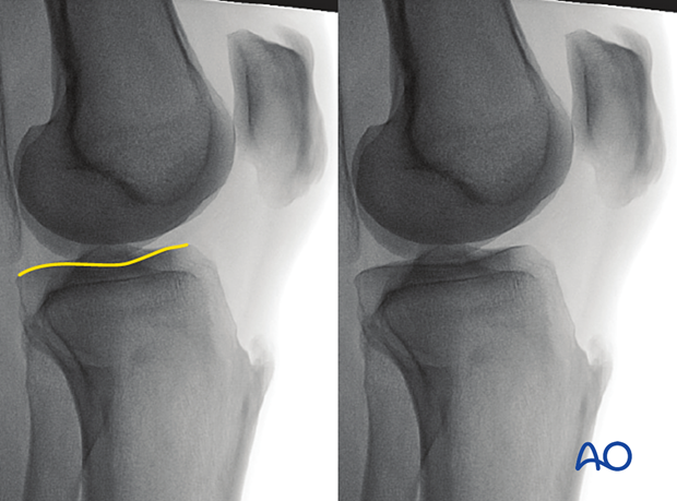
- the contour of the concave medial plateau is seen in the joint space cranially to the convex medial plateau.
- the medial tibial plateau is centered on the screen.
Anatomical lines and landmarks
The following lines and landmarks can be observed:
- Medial tibial plateau
What can be observed
This view is particularly useful to identify:
- Incongruency of the joint line
- Joint penetration of hardware
