Intraoperative imaging of the proximal humerus
1. Introduction
Fluoroscopic visualization of anatomical fracture reduction and correct implant placement for the proximal humerus can be greatly facilitated using the following views:
- AP view of the shoulder
- Lateral (axial) view of the proximal humerus
- Scapular-Y (Neer’s) view (especially for nailing)
The axillary view is usually not necessary for the treatment of a proximal humeral fracture.
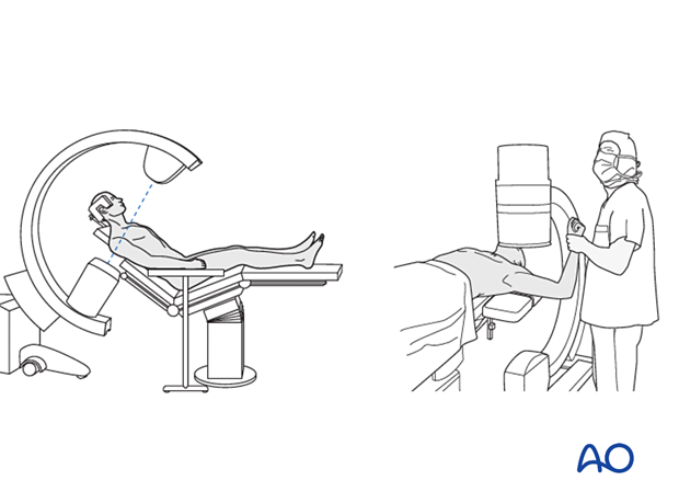
The following represents ideal imaging with the patient placed in the supine or various angles of beach chair position.
The orientation of the C-arm has to be adjusted.
2. AP view
Positioning for optimal view
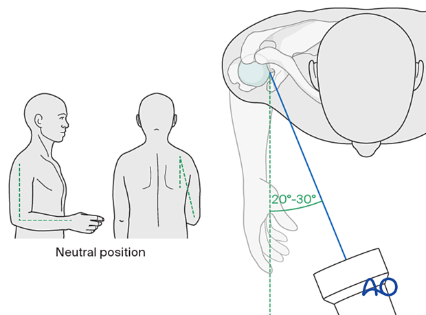
The arm is in neutral position.
Position the beam centered over the humeral head.
It should be 20°–30° tilted inward in the axial plane, parallel to the glenoid joint surface.
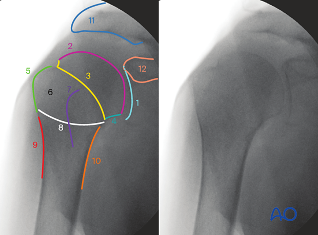
Anatomical landmarks and lines
The following lines and landmarks can be observed:
- Glenoid fossa
- Head of humerus
- Anatomic neck
- Calcar humerale
- Greater tuberosity
- Intertubercular groove
- Lesser tubercle
- Surgical neck
- Lateral line
- Medial line
- Acromion
- Coracoid
This image is taken with the patient in supine position. Images with the patient in the beach chair position should look the same.
Verification of optimal view
The optimal view is obtained when:
- Minimal overlap of head and glenoid
- Head centered in the glenoid (depending on fracture)
- Visibility of greater tuberosity
- Head and shaft visible
What can be observed
This view is particularly useful for identifying:
- Glenohumeral dislocation and subluxation
- Varus and valgus displacement of the head
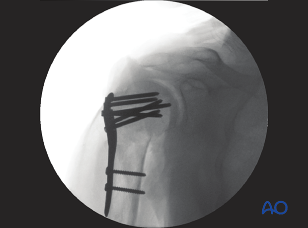
- Plate position
- Intraarticular screw
3. Lateral (axial) view
To obtain a lateral (axial) view, the arm needs to be externally rotated with abduction. This is only possible after the fracture is fixed preliminarily or definitively.
In other cases, the C-arm needs to be rotated (see Neer’s view below).
Positioning for optimal view
With the beam in the same position as for the AP view, rotate the arm externally (or internally) 90° from the neutral position.
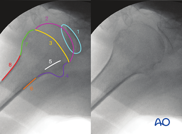
Anatomical lines and landmarks of the proximal humerus in the lateral view
The following lines and landmarks are seen:
- Glenoid fossa
- Head of humerus
- Anatomic neck
- Lesser tuberosity
- Bicipital sulcus
- Anterior line
- Greater tuberosity
- Posterior line
This image is taken with the patient in a beach chair position. Images with the patient in supine position should look the same.
Verification of optimal view
The optimal view is obtained when the following is visible:
- Minimal overlap of head and glenoid
- Head centered in the glenoid (depending on fracture)
- Visibility of greater and lesser tuberosity
- Humeral head and neck are in axial alignment with the shaft
What can be observed
This view is particularly useful for identifying:
- Posterior displacement of the humeral head
- Plate malposition
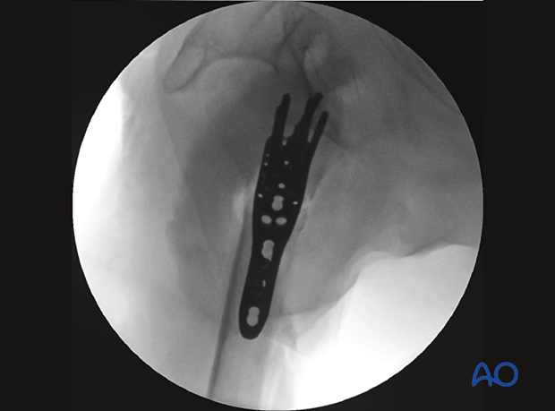
This image shows slight residual posterior displacement of the humeral head.
4. Dynamic image intensification
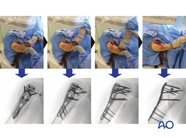
With the beam set for an AP view, position the patient to allow arm rotation.
Continuously rotate the arm from neutral to 90° external rotation under fluoroscopy to obtain a range of views from correct AP to lateral (axial).
What can be observed
- Intraarticular screw (image)
- Relation of plate to shaft
5. Neer’s view (scapular-Y view)
Positioning for optimal view
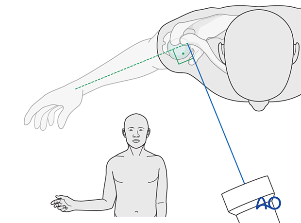
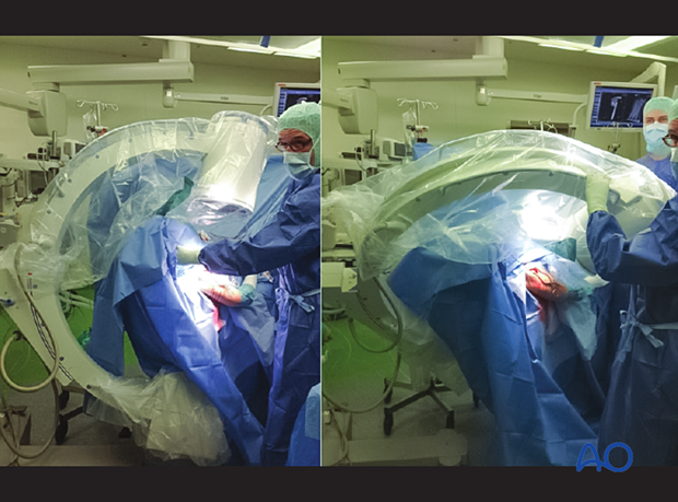
Neer’s view is perpendicular to the AP view without manipulating the fractured arm. This necessitates repositioning the C-arm.
Position the patient and beam for the AP view. Swing the C-arm 90° around the shoulder to obtain a view perpendicular to the glenoid.
Before starting the surgery, ensure the patient and C-arm position allows this maneuver. A shoulder table (radiolucent) is necessary.
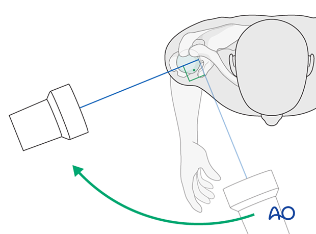
Left image: C-arm position for AP view
Right image: C-arm position for scapular-Y view
Note: Patient and arm position are not changed.
Anatomical lines and landmarks
The following lines and landmarks are seen:
- Coracoid
- Scapular spine
- Scapular body
- Acromion
- Lateral clavicle
- Glenoid
- Humeral shaft
- Lesser tuberosity
- Humeral head
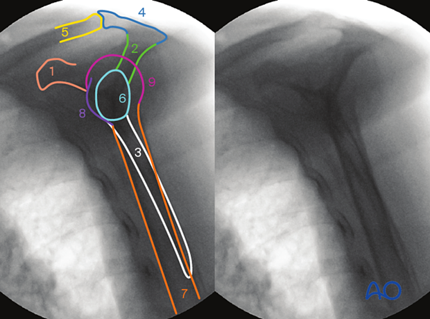
Verification of optimal view
The optimal view is obtained when the following is visible:
- Scapular body, coracoid, and spine form a Y-shape
- Humeral shaft and head are projected on the glenoid and scapular body
What can be observed
This view is particularly useful for identifying:
- Alignment of humeral head and shaft
- Signs of anterior or posterior subluxation/glenohumeral dislocation
- Correct implant placement
- Correct entry point for nailing
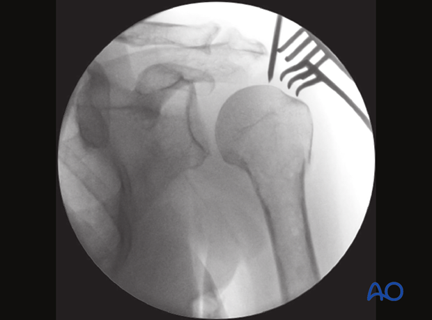
This AP view shows the guide wire for nail insertion pointing slightly lateral to the apex of the head for a bent nail.
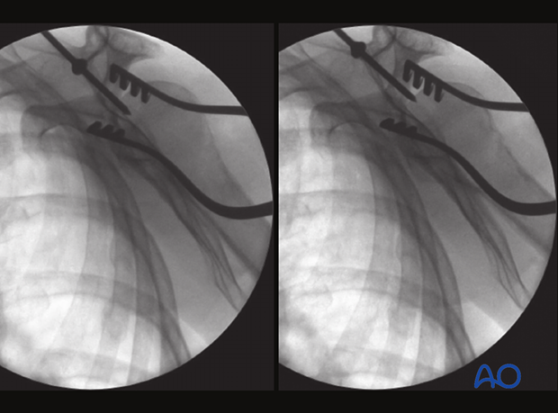
These images show Neer’s view of the same case. The left image shows the guide wire too posteriorly. In the right image, this has been corrected with the wire in line with the medullary canal.
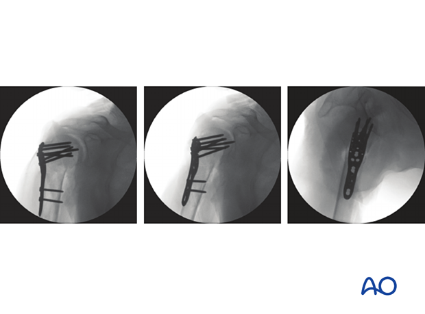
Final intraoperative views of the above case
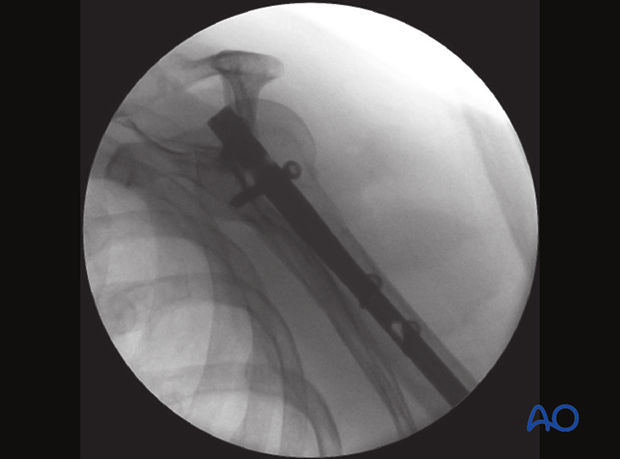
AP view of the above case with the nail inserted and fixed with screws to the humeral head, the insertion handle still in place.
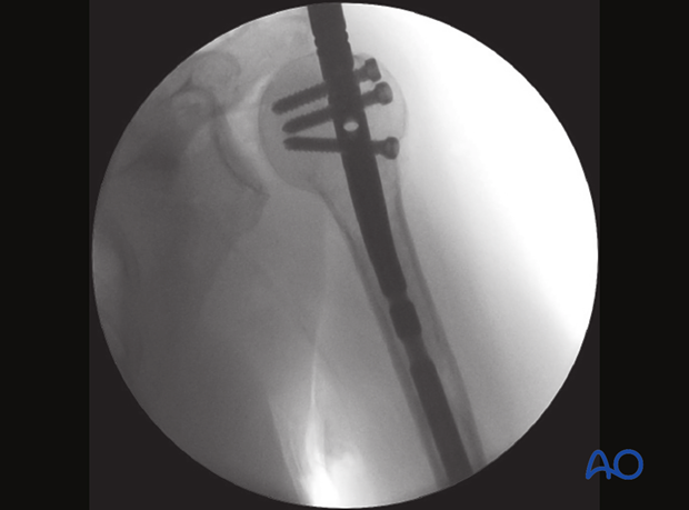
Final lateral (axial) view of the nailing procedure
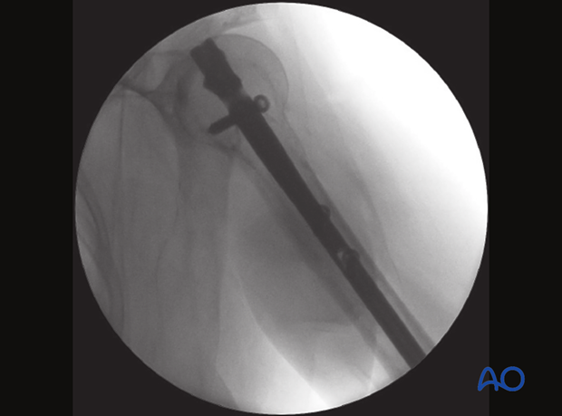
Final Neer’s view
