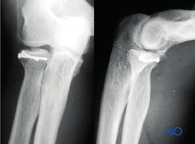
Radius, partial articular - Lag screw
1. General considerations
Lag screw principles for the radial head
In two-part partial articular fractures of the radial head, fixation can be achieved by lag screws.
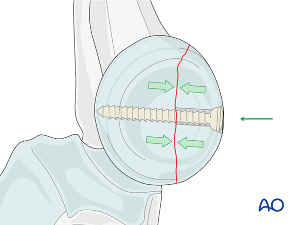
The thread pulls the opposite bone fragment towards the head of the screw placing the fracture ends under compression. The portion of the thread in the gliding hole does not purchase in the surrounding bone.
Because the radial head is completely covered by articular cartilage the screw heads must be countersunk just below the level of the articular cartilage. The screw tip must not protrude medially, as it will contact the ulna and interfere with supination/pronation.
2. Screw positioning
For the insertion of the screws, choose a location in the radial head that causes the least compromise of full pronation and supination. Insert the lag screw(s) as perpendicularly to the fracture plane as possible.
Safe zone for screw insertion
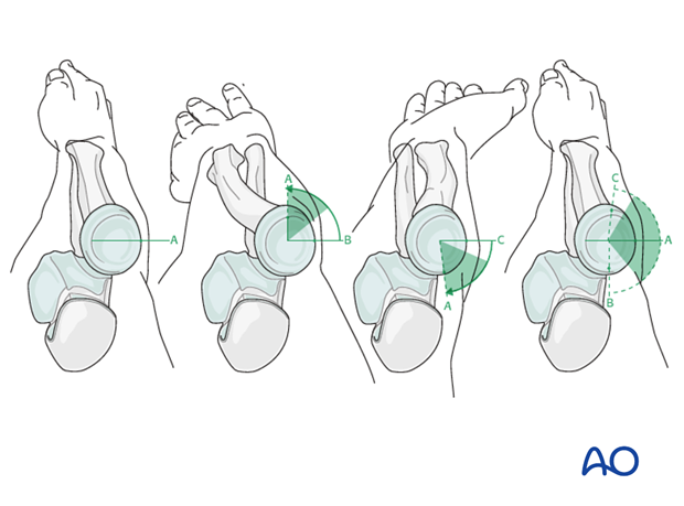
To determine the location of the “safe zone”, reference marks are made along the radial head and neck, to mark the midpoint of the visible bone surface. Three such marks are made with the forearm in neutral rotation, full pronation, and full supination as shown in the illustration. The posterior limit of the safe zone lies halfway between the reference marks made with the forearm in neutral rotation and full pronation. The anterior limit lays nearly two thirds of the distance between the neutral mark and the mark made in full supination.
Note: The nonarticulating portion of the safe zone for the application of implants to the radial head (or safe zone for prominent fixation) consistently encompasses a 90 degrees angle localized by palpation of the radial styloid and Lister’s tubercle.
3. Choice of implant
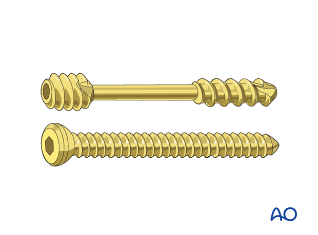
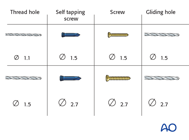
1.5 mm or 2.0 mm screws, or headless compression screws (Herbert or similar screws) are used.
4. Reduction and preliminary fixation
Reduction of stable fractures
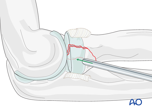
In minimally displaced and stable fractures, there is no need to open the fracture site. The deformity can be corrected using a tamp.
Reduction of unstable fractures
In unstable fractures, the fracture can be opened to clear out soft tissue, hematoma and interposed fragments.
Expose the fracture ends with minimal soft tissue dissection.
If the radial head has been dislocated posteriorly, confirm that it is satisfactorily reduced to the capitellum.
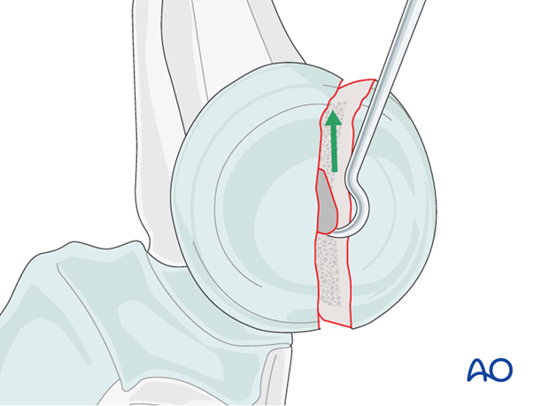
Reduction is achieved directly.
If the annular ligament is still intact, cut and retract it to achieve better access to the fracture site.
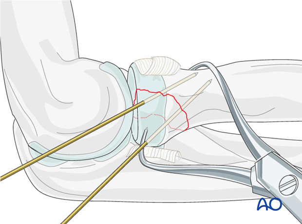
Reduce and provisionally fix the fracture with the help of small pointed reduction forceps and one or two K-wires.
Anticipate the final screw position prior to temporary K-wire placement.
5. Screw positioning
Drilling
Plan the number and location of screws.
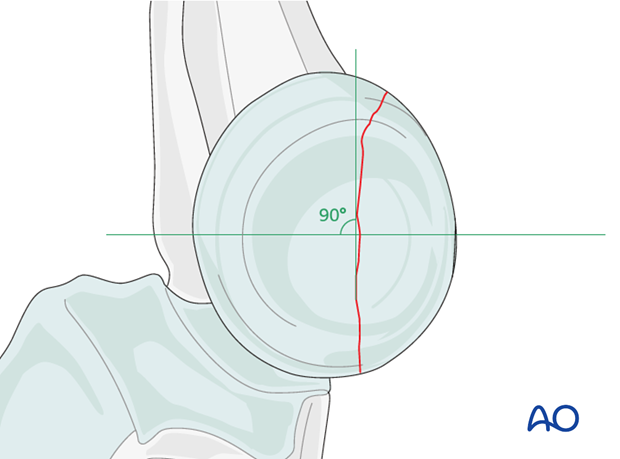
The lag screw is ideally directed perpendicularly to the fracture plane.
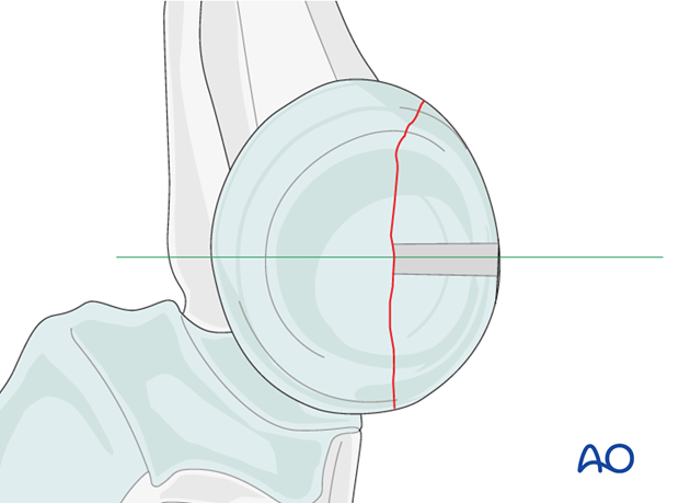
Drill a gliding hole into the free fragment, sized according to screw size.
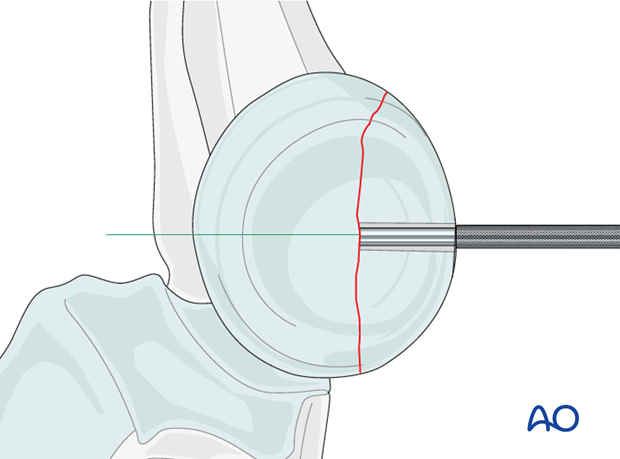
Insert the appropriate drill sleeve into the gliding hole until it reaches the fracture.
Now drill the epiphysis of the intact radial head with the appropriate drill bit.
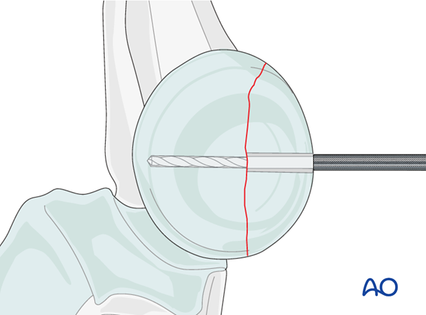
Countersinking and measuring
Countersink the cartilage covering the free fragment to prevent protrusion of the screw head.
Measure the depth of the hole and place the screw. If self-tapping screws are not available, tap the far epiphysis with the appropriate cortical tap and protection sleeve.
Note: Always measure after countersinking to prevent penetration of the screw tip into the joint.

Lag screw insertion
Closely observe the compression effect on the fracture line while tightening the lag screw.
Any K-wire(s) should be removed just before the final tightening of the screw.
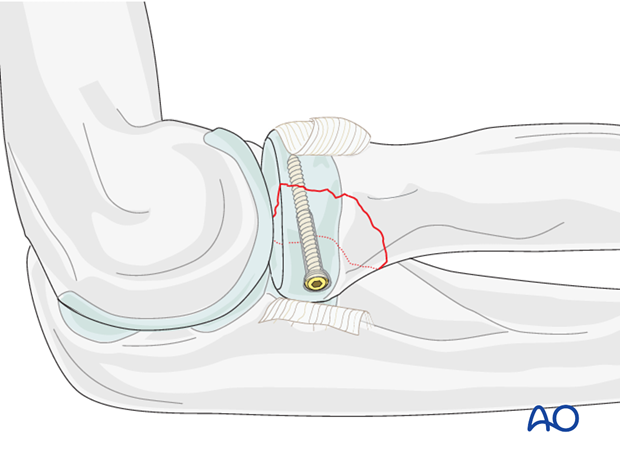
Second lag screw
If fragment size permits, a second lag screw will improve strength of fixation. It can be inserted now using the same technique as described above.
Note: Check reduction and screw length with supination/pronation exam. Screws should not obstruct rotation.
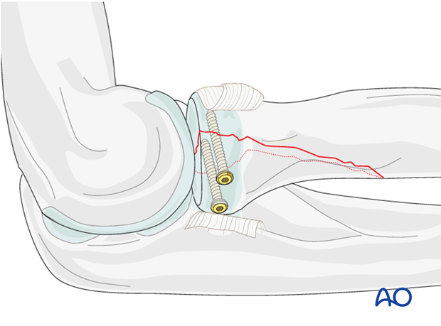
Alternative fixation - headless compression screws
When headless compression screws (eg, Herbert or HCS) are used, there is no need for countersinking as the screw head engages inside the bone.
After reduction, provisionally fix the fracture inserting one or two K-wires in the previously planned screw position. Over the K-wire, insert the cannulated screw.
Preparation for screw insertion should be performed according to the surgical technique of the specific screw.
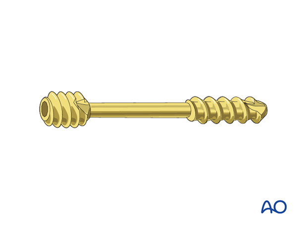
6. Ligament repair
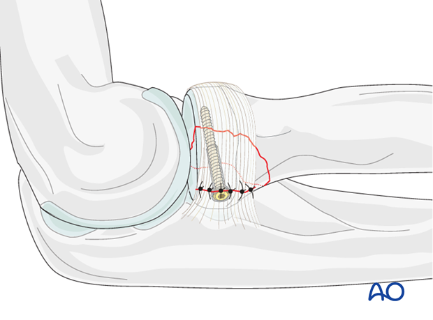
Repair the annular ligament using non-absorbable sutures.
7. Final assessment
Also check supination and pronation. Fixation should be stable. Crepitus or restricted motion should be absent.
Check fractures and fixation with image intensifier or x-ray.
