Radius, complete articular - Plate and screws
1. General considerations
Multifragmentary radial head fractures
In three-part fractures (including the shaft) where the fragment configuration allows reconstruction, the radial head is reconstructed with lag screws and attached to the shaft with a T-plate. Proximal radius fractures with more than three fragments can usually not be repaired satisfactorily and might necessitate radial head replacement based on injury pattern.
The lag screws may be inserted through the proximal holes of the plate (preferably) or separate.
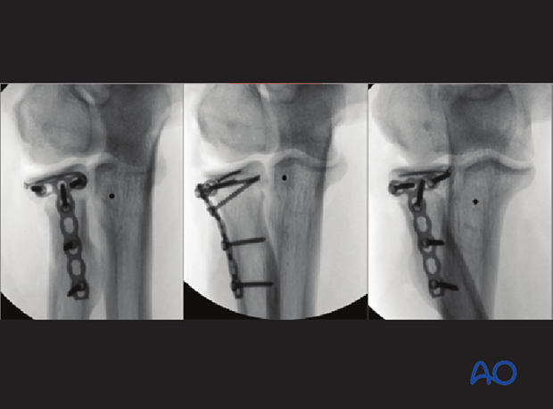
In rare cases, a side table assembly can be performed of the entire head and replaced to the shaft with a T-plate.
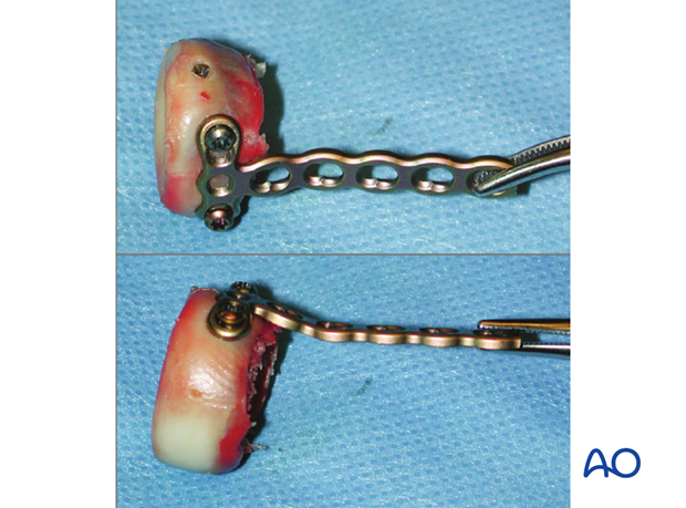
2. Positioning of plate and screws
The radial head is completely covered with articular cartilage. The implant is applied to the radial head in a location that causes the least compromise of full pronation and supination.
Safe zone for plate and screw insertion
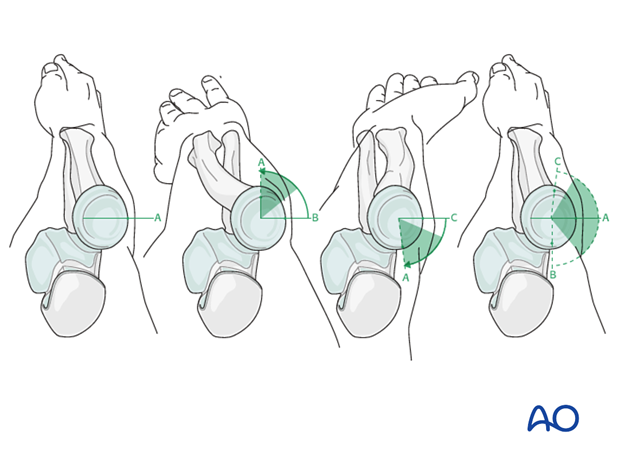
To determine the location of the “safe zone”, reference marks are made along the radial head and neck, to mark the midpoint of the visible bone surface. Three such marks are made with the forearm in neutral rotation, full pronation, and full supination as shown in the illustration.
The posterior limit of the safe zone lies halfway between the reference marks made with the forearm in neutral rotation and full pronation. The anterior limit lies nearly two thirds of the distance between the neutral mark and the mark made in full supination.
Note: The non-articulating portion of the safe zone for the application of implants to the radial head (or safe zone for prominent fixation) consistently encompasses a 90 degrees angle localized by palpation of the radial styloid and Lister’s tubercle.
3. Reduction and preliminary fixation
Exposure
Release the annular ligament as necessary to see the radial head and neck.
Expose the fracture with minimal soft-tissue dissection off the bone.
Remove hematoma and irrigate.
Reduction
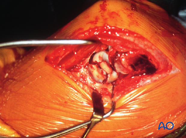
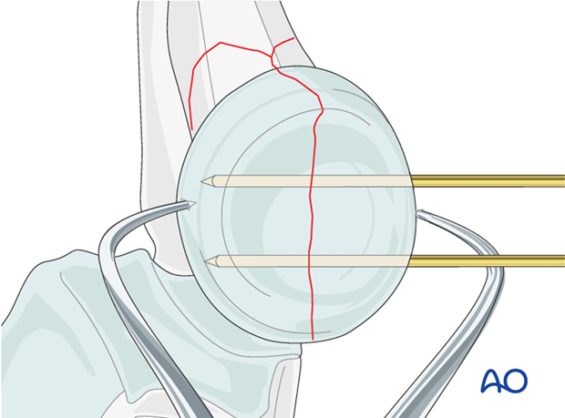
Directly reduce the joint fragments with the help of small pointed reduction forceps and provisionally fix them with two K-wires.
If joint depression is encountered, the depressed joint fragment is elevated, and the underlying defect may be bone grafted with bone from the lateral humeral condyle.
4. Plate preparation
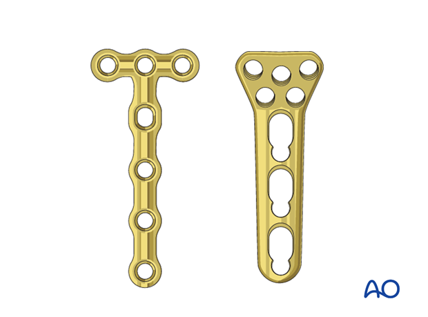
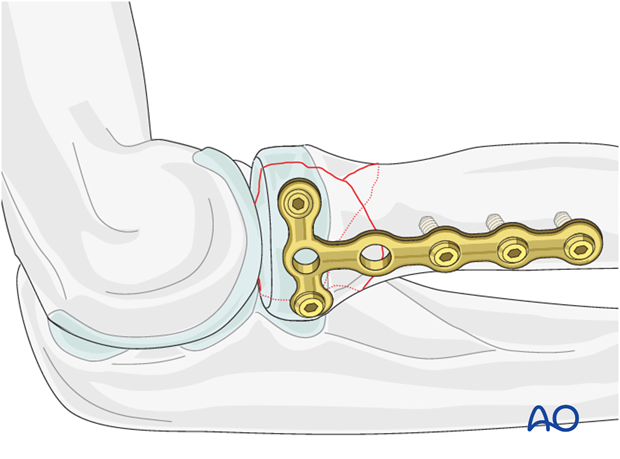
As the radial head is often a small fragment, 1.5 or 2.0 T-plate, or a locking proximal radius plate is used to allow purchase of two or three screws in the proximal fragment.
Carefully contour the plate according to the surface anatomy of the proximal radius.
Even with anatomic plates, a perfect fit is often difficult to obtain. Given the requirements for a low-profile fixation these anatomic plates may need to be recontoured.
5. Proximal fixation with lag screws and plate
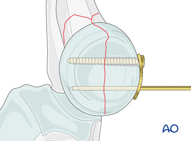
Apply the properly contoured plate to the radial head and insert two horizontal lag screws (1.5 or 2.0 mm) into the proximal fragment.
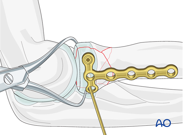
These screws are inserted through the plate to achieve absolute stability of the anatomically reduced joint fragment.
Note: The plate position on the radial head is dictated by the fracture configuration to allow optimal stability and function. If the latter is not possible with the lag screws through the plate, the lag screws may be inserted outside the plate and the plate is fixed in its optimal position.
6. Distal plate fixation
Finally attach the plate to the radial shaft with two or three screws, thereby fixing the joint fragment to the diaphysis.
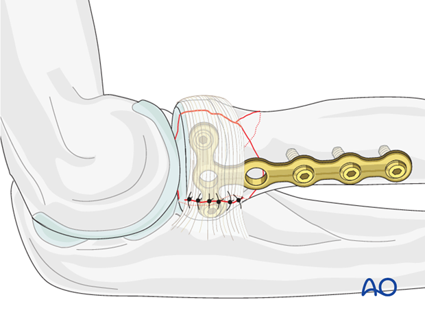
7. Ligament repair and test of stability
Repair the annular ligament using non-absorbable sutures.
8. Final assessment
Check supination and pronation. Fixation should be stable. Crepitus or restricted motion should be absent. Check fractures and fixation with image intensifier or x-ray.


