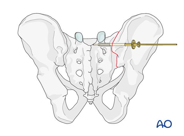
Iliosacral screw navigation
1. Introduction
Note: This description focuses on the use of navigation to guide IS fixation. For detailed considerations of IS screw insertion, (safe channels, reduction etc.), please refer to the descriptions of the conventional IS screw techniques.
In most hospitals real time information regarding the exact position of instruments within bone and soft tissues is achieved using image intensifier fluoroscopy. This technique requires significant radiation exposure and is time consuming.
The aim of intraoperative navigation is to achieve the same while minimizing the radiation exposure.
Intraoperative navigation as presented in this text provides information on screw entry point and trajectory relative to the sacrum. It does not provide information about pelvic alignment and reduction.
System components
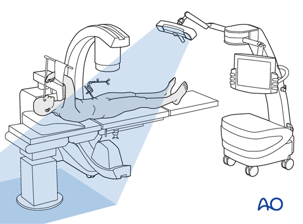
The navigation system consists of the following three components.
- Computer unit with monitor
- Infrared camera (tracking unit)
- Infrared-emitting trackers attached to the surgical site, surgical instruments and the C-arm
For accurate navigation, it is essential that the trackers are rigidly fixed to the instrument or bone segment being tracked.
Registration
By attaching trackers to the C-arm and the iliac crest, their relative spatial position can be triangulated with the tracking camera.
This triangulation permits images to be recorded (inlet, outlet, lateral, and AP view) in the computer unit together with the exact location of the imaged structures in space.
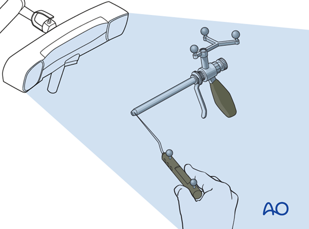
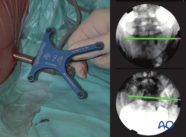
Trackers attached to the drill sleeve allow the infrared camera to continuously feed the computer unit with its exact location and orientation in space.
Tracking
The computer unit integrates the virtual image of the tracked instrument into the on screen X-ray.
As the tracked components (pelvic ring and drill sleeve) move relative to each other (left), the computer unit will display on screen (right) how the drill sleeve (pink) and trajectory (green) move relative to the patients anatomy on X-rays in all views simultaneously (here only two views are show).
Validation
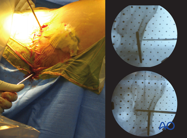
At regular intervals throughout the procedures a C-arm image is acquired to verify that the location of the actual guide correlates to the virtual guide wire.
2. Reduction
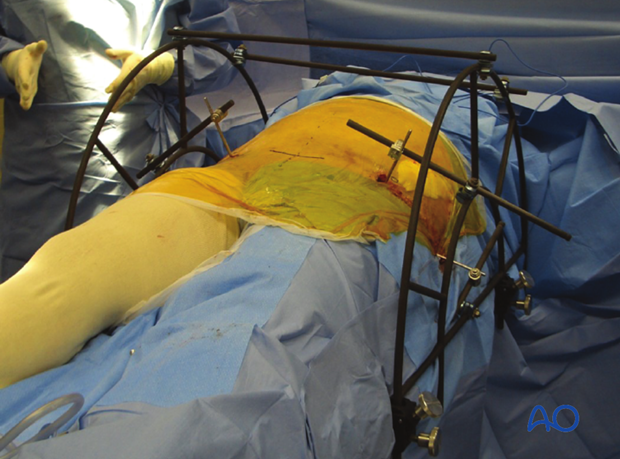
When intraoperative computerized navigation is used, it is essential to the accuracy of the procedure that the reduced segments of the pelvic ring do not move relative to each other during the procedure. Any movement will lead to inaccurate orientation of instrumentation.
To achieve this, a table mounted skeletal pelvic fixation frame can be used. This combines external fixators with reduction possibilities in all 3 dimensions.
Such a frame will not be required for a minimally displaced stable SI disruption.
For open book (external rotation) fractures, it is advisable to fix both feet together in internal rotation, which usually produces a significant improvement of external rotation deformity, at least for type B injuries.
If acceptable reduction cannot be achieved by a closed technique, an open reduction technique should be performed.
Correction of internal and external rotation
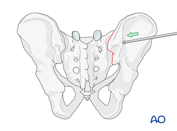
For internal and external rotation of the hemi pelvis, Schanz screws can be inserted in the supra acetabular area and/or ala. These are then used as joy sticks until reduction is achieved. The Schanz pins are held in place either manually or by attachment to an external frame (as an external fixator) until fixation is completed.
Correction of minor lateral displacement
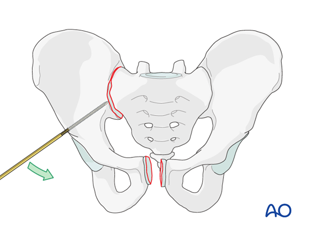
If only a compression of the joint is necessary, a ball spike can be used through a separate incision to reduce the SI joint.
If acceptable reduction cannot be achieved by a closed technique, an open reduction should be performed.
Correction of SI dislocation with associated disruption of the symphysis
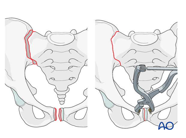
If SI dislocation is associated with disruption of the symphysis, open reduction with temporary fixation of the symphysis is performed first.
This will partially reduce the SI joint.
If only a small widening of the SI joint remains in AP view with no vertical or horizontal displacement (inlet and outlet view in good position),then the iliosacral screw will compress the joint and complete the reduction.
Correction of vertical displacement
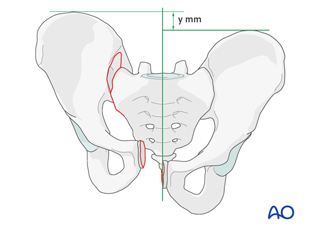
Correction of vertical displacement may be challenging to achieve.
In cases of vertical displacement where the contralateral hemipelvis is intact, the patient can be placed on a radiolucent traction table. Traction is applied until correct reduction can be seen on AP outlet and inlet projections. The traction is then maintained until fixation is completed.
Temporary fixation
When reduction is completed, it needs to be secured to ensure accuracy of the computerized navigation.
3. Insertion of SI screw using navigation
Registration
The reference frame is attached to the iliac crest and the pelvic ring is registered in inlet, outlet, lateral, and AP view with the registered C-arm.
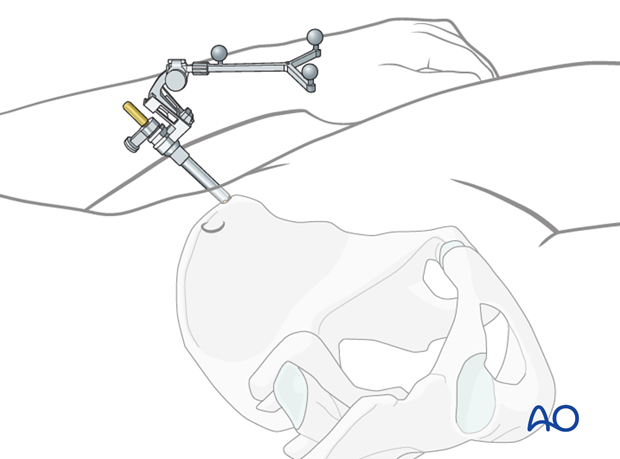
The drill sleeve is registered and will be tracked throughout the procedure.

Correct patient registration is confirmed by placing a registered pointer onto an anatomical landmark of the pelvic ring. If the virtual pointer is not pointing to the corresponding landmark in the on-screen X-ray, the registration is incorrect and will need to be repeated.
Landmarks for stab incision
The virtual trajectory line originating from the tracked drill sleeve is used to determine the location of the stab incision.
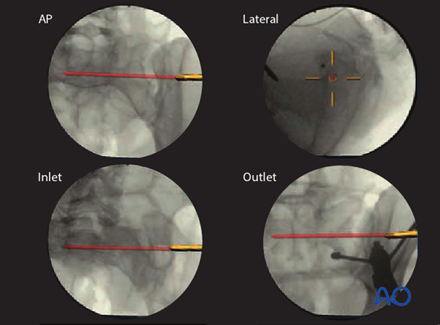
After the stab incision is made, the drill sleeve is inserted down to the ilium.
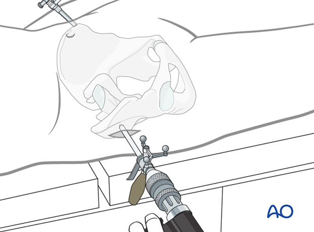
The position of the drill sleeve (pink) is adjusted until the virtual beam (green), which represents the guidewire, has an optimal entry point on the ilium and direction into the sacral vertebra (S1 or S2).
A safe zone for the screw insertion should be available.
The correct screw length and width can now be determined based on the virtual trajectory. The screw should reach well into the sacral vertebral body.
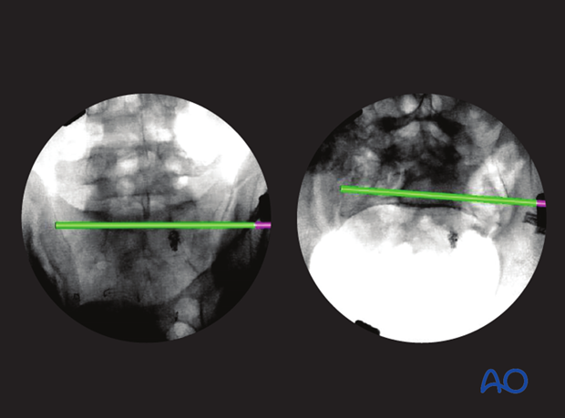
The guide wire is now inserted through the drill sleeve.
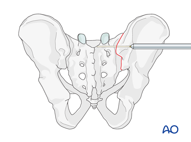
Validation
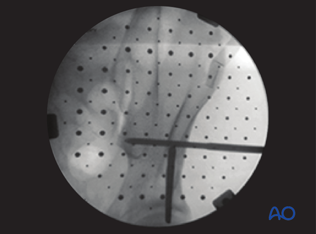
A C-arm image is recorded to validate that the virtual guide wire trajectory correlates to the actual guide wire direction.
If the validation fails, the equipment should be checked and the procedure restarted with new registration.
The screw is then inserted over the guide wire and the guide wire removed.
