External fixation
1. General considerations
External fixation of the pelvis is indicated for temporary or definitive stabilization of unstable pelvic ring injuries.
Although the techniques can be performed without x-ray guidance, the use of x-ray guidance is recommended, especially when using supra acetabular pins.
Following temporary stabilization, after the patient is resuscitated, the external fixation may be converted to internal fixation. This is preferred as prolonged external fixation may lead to patient discomfort, skin problems, and local infections.
It is important to remember that external fixation (whether supra acetabular or iliac crest) predominantly controls and stabilizes the anterior pelvic ring. In most cases supplemental stabilization or fixation is required for associated posterior pelvic ring injuries.
Placement of the iliac crest external fixator is problematic in obese patients.
This procedure is not fracture-specific and therefore illustrated using an intact pelvic ring. When there is pelvic disruption the orientation of the two innominate bones to each other is disturbed. The pins must be placed on each side wherever the bone lies. This may appear odd until the disruption is corrected.
Teaching video
AO teaching video: Pelvis – Pelvic Ring Instability – Large External Fixator: Stabilization of the Pelvic Ring
2. Patient positioning
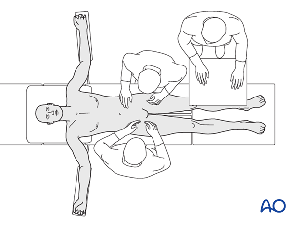
Place the patient in the supine position on a radiolucent table.
A urinary catheter should be inserted prior to beginning the procedure.
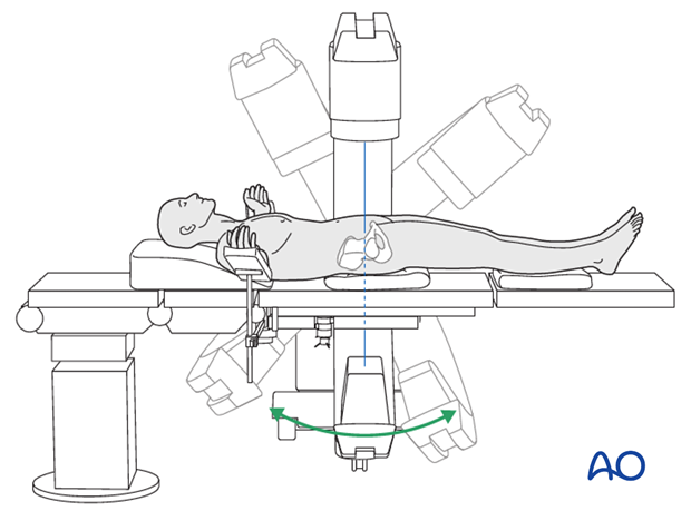
Prior to starting the procedure fluoroscopic AP, inlet and outlet x-rays should be obtained to ensure adequate visualization.
Prior to draping, ensure that the C-arm is able to obtain the necessary images without being obstructed by the table.
The legs should be accessible for possible reduction maneuvers, but not necessarily prepped and draped. A pillow to flex the hip can help to relax the neurovascular structures and iliopsoas muscle if desired for anterior pelvic approach. All pressure points should be padded.
3. Equipment needed
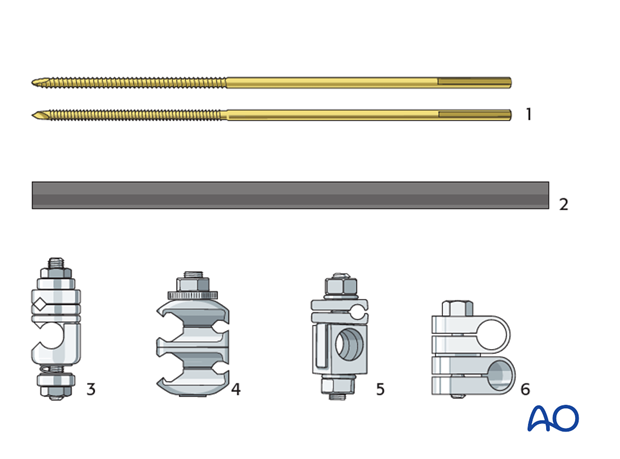
For the construction of the frame the following components are needed (shown for the large external fixator):
- Threaded pins (Schanz type pins, standard or self-drilling/self-tapping with radial preload; 5 or 6 mm)
- Carbon fiber rods or metal tubes (diameter of 11 mm)
- Rod-to-pin clamps (titanium, MRI safe)
- Combination clamps (rod-to-rod or rod-to-pin, self-holding, titanium, MRI safe)
- Rod-to-pin clamps (old type, still in use)
- Rod-to-rod clamps (old type, still in use)
For the application of special frames, further components may be needed.
4. Pin insertion in supra acetabular position
Introduction
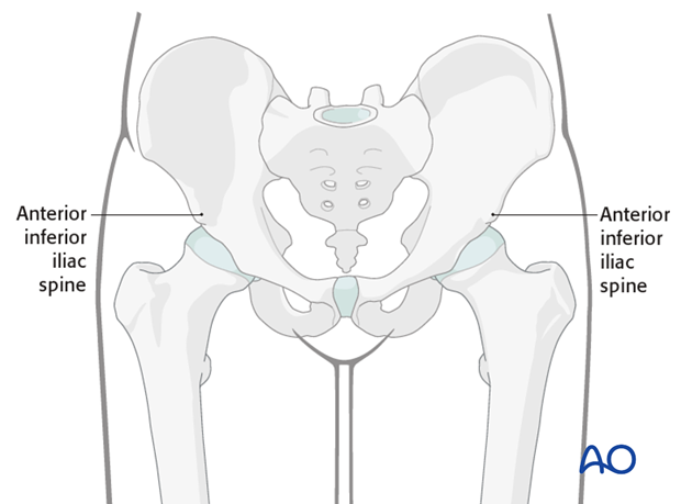
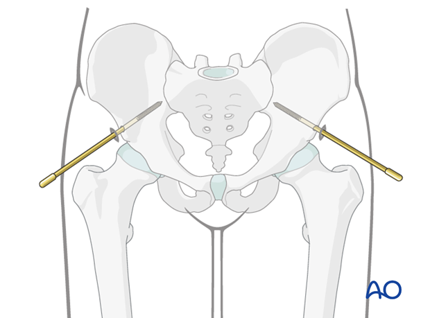
Insertion of threaded pins in the supraacetabular region is performed by using the anterior inferior iliac spine (AIIS) as a starting point.
This procedure can be performed either:
- percutaneously with fluoroscopic guidance, or
- by making an incision and palpating the AIIS.
Potential risk
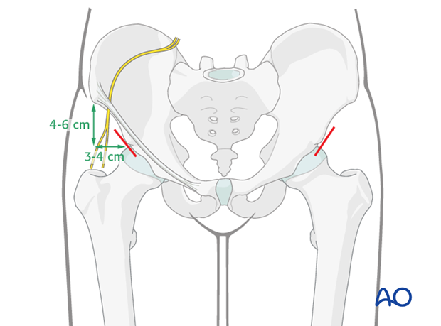
The lateral femoral cutaneous nerve is at risk during placement of pins in the AIIS.

Placement of pins through an open approach
A 2-3 cm oblique incision is made approximately 4-6 cm distal and 3-4 cm medial to the anterior superior iliac spine.
The skin is incised and the subcutaneous tissues are spread. The anterior inferior iliac spine is palpated through the incision.
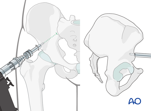
The drill guide is placed on the superior portion of the AIIS. The drill and subsequently the pins should be aimed proximally towards the SI joint. Once the appropriate starting point is identified, the outer cortex is perforated with the drill.
Aiming the drill and the pins proximally helps to avoid penetration of the hip joint.
Again the drill should be inserted only through the anterior cortex.
Using a T-handle, the pin is inserted.
The pin should be directed approximately 10-20° cranially and 20-30° medially.
Advance the pin as far as possible into the posterior aspect of the ilium in order to improve purchase in the bone. This is important in osteoporotic bone.
Now prepare the opposite side in the same way.
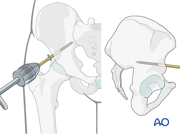
Percutaneous placement of pins with fluoroscopic guidance
The anterior inferior iliac spine is identified with the image intensifier.
A stab incision is made at this location.
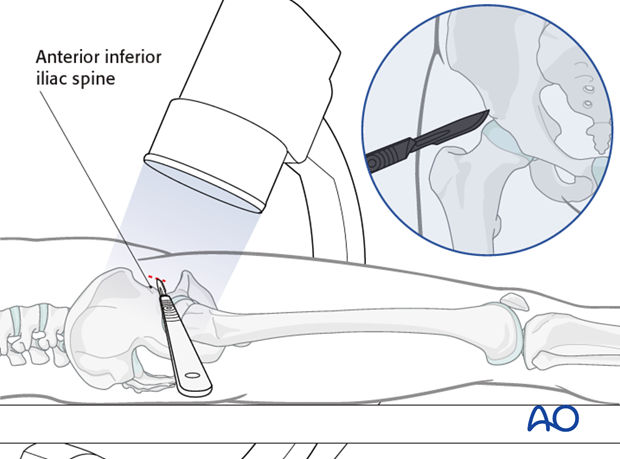
The pin is placed through the stab incision directly onto the AIIS. 3 fluoroscopic views are used to confirm the position and trajectory of the pin.
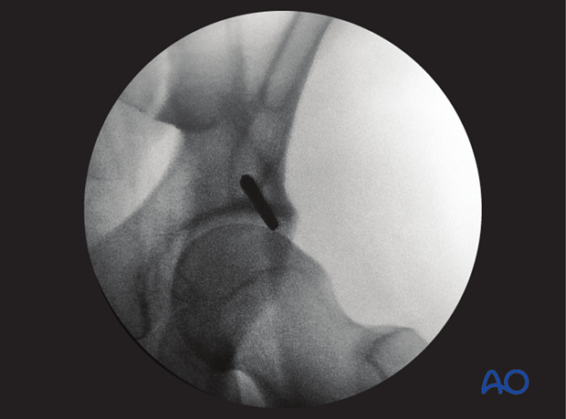
Once the position and trajectory of the pin are confirmed, the pin is advanced into the posterior aspect of the ilium.
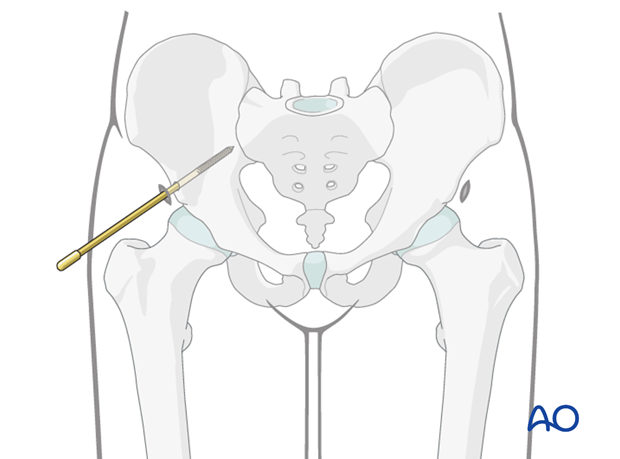
Repeat this procedure on the opposite side.
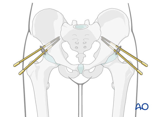
In case of prolonged external fixation, two pins on each side should be considered.
In this case, one pin should be inserted slightly above the AIIS and the other below. The distance between them should be approximately 1 cm.
5. Pin insertion in the iliac crest
Skin incision
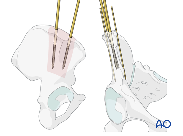
Determine the orientation of the iliac wing through palpation with a finger or instrument (eg K-wire).
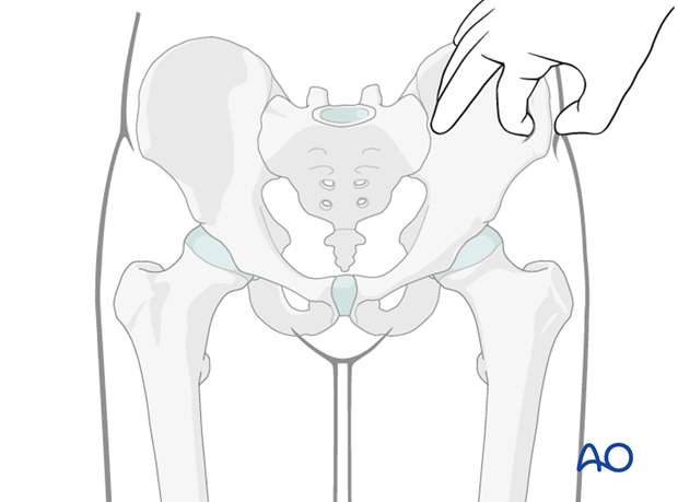
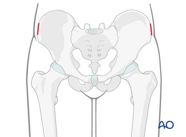
Make a 1-2 cm incision along each iliac crest.
Determination of entry point
The anterior third of the iliac crest is well suited for pin placement because 1) the bone is usually easily palpable and 2) the iliac crest is wide enough to accommodate the pin in this region.
Pins should be placed in the iliac crest approximately 15 mm posterior to the anterior superior iliac spine (ASIS). This is the thickest portion of the ilium (referred to as the gluteus medius pillar).
Pins should not be inserted within 15 mm of the ASIS. Placement of pins in this region may injure the lateral femoral cutaneous nerve.
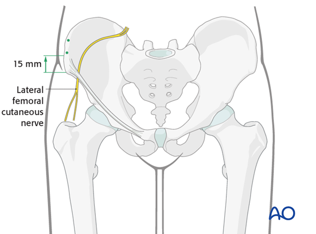
K-wires may be placed along the inner table and outer table of the iliac wing in order to aid in the placement of the pins.
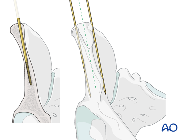
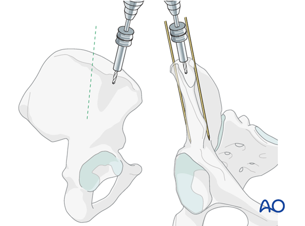
Drilling and insertion of pins
The cortex of the iliac crest may be perforated with a drill.
Using a T-handle the pin is inserted between the inner and outer table of the iliac wing.
Perforation of either the inner or outer table should be avoided as this will impair purchase and reduce stability.
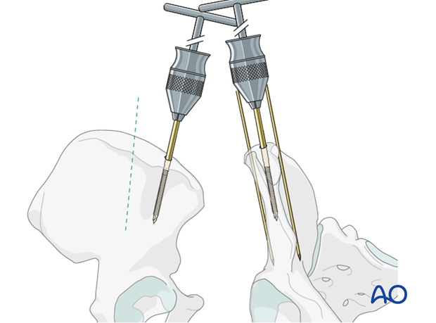
A second pin is inserted in a similar fashion approximately 1 cm posterior to the first pin.
Two pins are then inserted in the contralateral iliac wing using the same technique.
6. Reduction and fixation
The remaining steps are essentially the same whether pins are inserted in the supra acetabular position or in the iliac crest. To illustrate the principles of the following steps we will use pins inserted in the supra acetabular position.
Placement of connecting rod
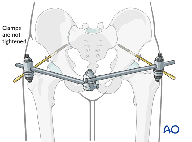
The pins are connected anteriorly using two rods connected with a rod-to-rod clamp.
The clamps are not tightened at this point as the pelvic ring is not yet reduced.
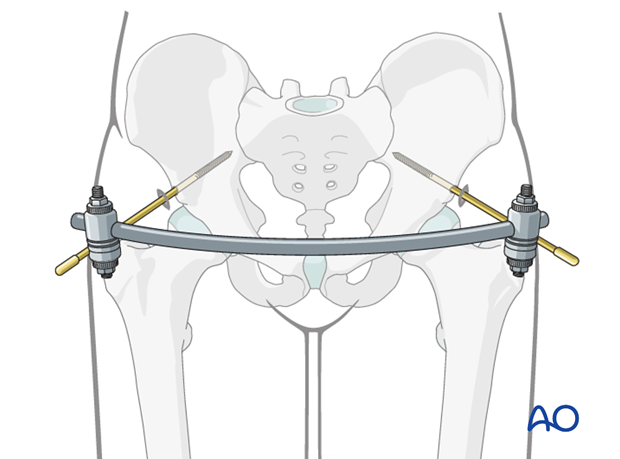
Different configurations may be utilized for the connecting rods. The following principles should be applied:
- The rod configuration should allow adequate room for the abdomen and for sitting.
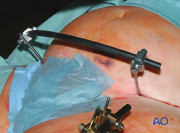
- A curved rod, if available, can be applied in case of non-obese patients.
Reduction
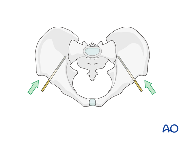
Closed manual reduction is performed using manual pressure laterally or utilizing the pins.
Manual reduction of external rotational displacement is performed by applying pressure at the level of the iliac crests or the greater trochanters.
Manipulation of the legs can be helpful to improve reduction.
Image intensification is used to assess the reduction and external rotation displacement. Subsequent reduction is best judged in an inlet radiograph.
For vertical displacement, reduction is performed by applying traction through the femur.
Vertical displacement and subsequent reduction is best judged in an outlet radiograph.
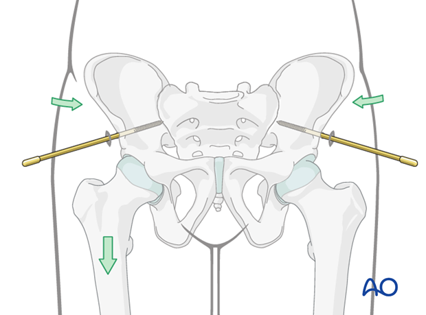
Fixation
Once reduction is achieved, the clamps are tightened.
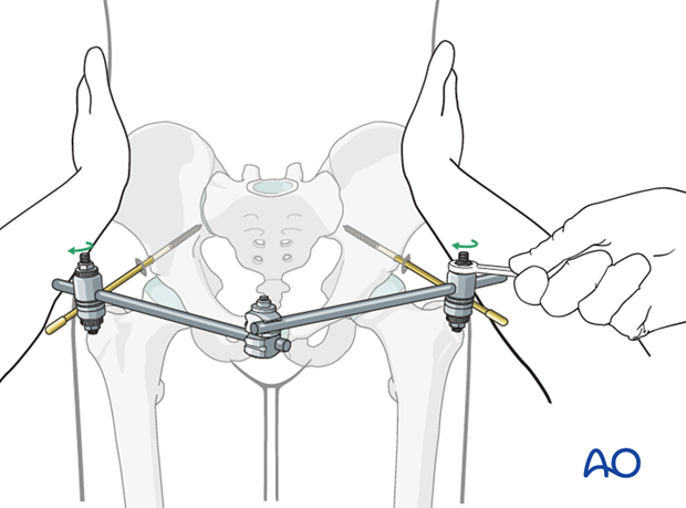
Option: Additional rod
An additional rod may be placed to increase stability.
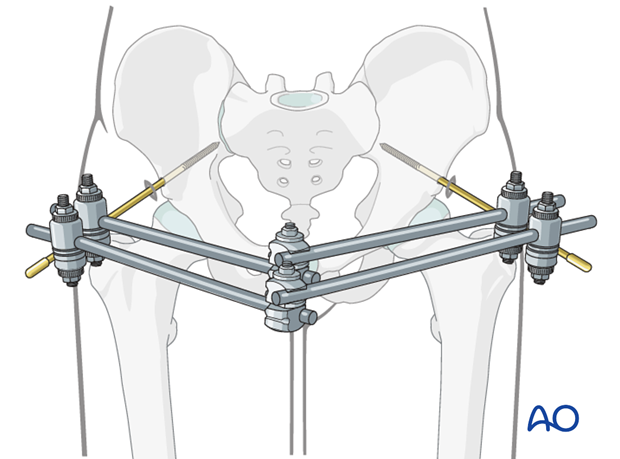
Inspection and treatment of skin incisions
After the operation stab incisions should be left open and treated locally with antiseptic dressings. Closing stab incisions prevents wound drainage, which increases the risk of pin-track infection.
If there is tension on one side, the incision should be extended. If significant extension is required so that the total incision is unnecessarily long the redundant portion of the incision may be closed.
Confirm that the hips can be flexed to 90°.
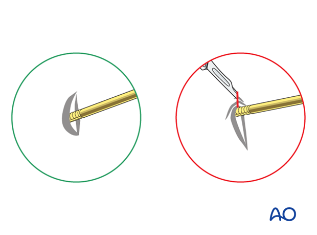
7. Check of reduction and fixation
Check
- pelvic reduction with imaging in three views,
- the external fixator pin sites for skin tension,
- fixator clearance for abdominal distension,
- hip flexion relative to fixator.
Unless a C-arm with a large field of view is available, it may be wise to obtain similarly oriented portable x-rays of the entire pelvis, to be certain about the overall alignment.

8. Subsequent management after external fixation as temporary fixation
If external fixation was used because the patient was not fit to undergo definitive internal fixation, once the general condition has improved, definitive fixation may be considered.
9. External fixation as definitive fixation
If the fixator was initially applied rapidly when the patient was severely injured, once a decision has been made to continue external fixation as definitive treatment, it may be necessary to adjust the fixator or insert additional pins to obtain more secure fixation.
10. Case example
An incision is made over the AIIS.

The drill guide is inserted through the incision.
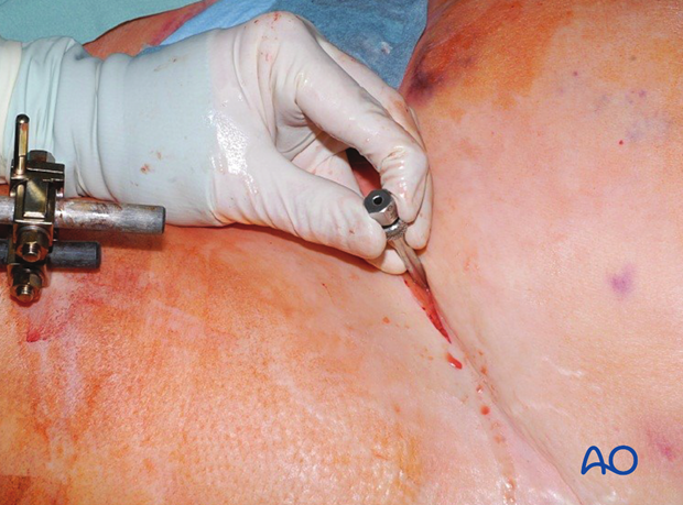
The outer cortex of the AIIS is perforated. Note the direction of the drill aiming 20° cranially and 30° medially.
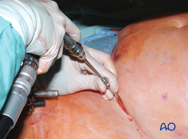
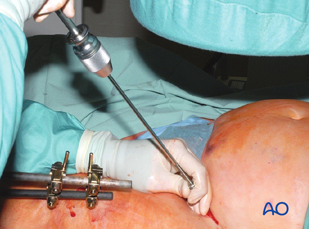
The pin is then inserted in the same direction.
Image intensification should be used before the pin is fully inserted, otherwise it may be inserted incorrectly.
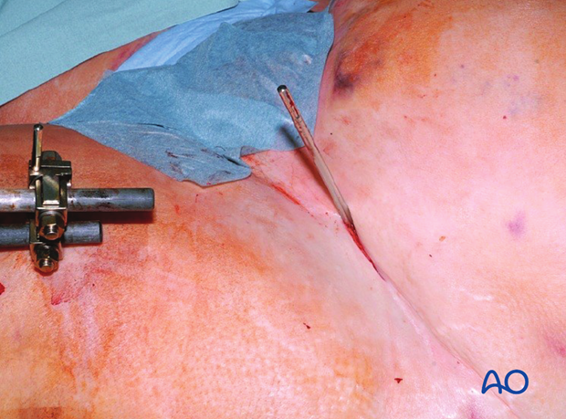
This picture shows the inserted pin.
The contralateral pin is inserted in the same way.
Image intensifier is used to confirm correct position of both screws.
The curved connecting rod is attached to the pin and tightened once proper reduction has been achieved.
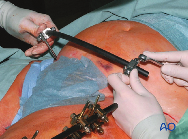
This picture shows the completed external fixator.
