Retrograde nailing approach to the femoral shaft
1. General considerations
Outcomes for retrograde nails are very similar to outcomes for antegrade nails. But, retrograde nails may be advantageous for distal third fractures.
Care should be taken with the approach for retrograde nailing as several anatomical structures are at risk. The most important potential hazard is damage to the anterior cruciate ligament. In addition, cartilage from the weight bearing zone may be damaged if a non-anatomic approach is selected. A non-anatomic approach can also lead to a failure to reduce the fracture properly, resulting in a varus/valgus malposition of the distal main fragment. Lastly, plunging out the back of the knee is always a major risk of this procedure because of the neurovascular structures.
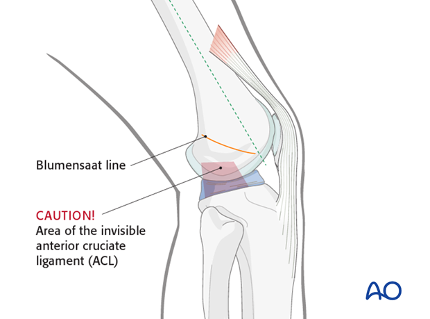
The anatomical landmark is the Blumensaat’s line (solid orange line) – this corresponds to the roof of the intercondylar notch.
2. Skin incision
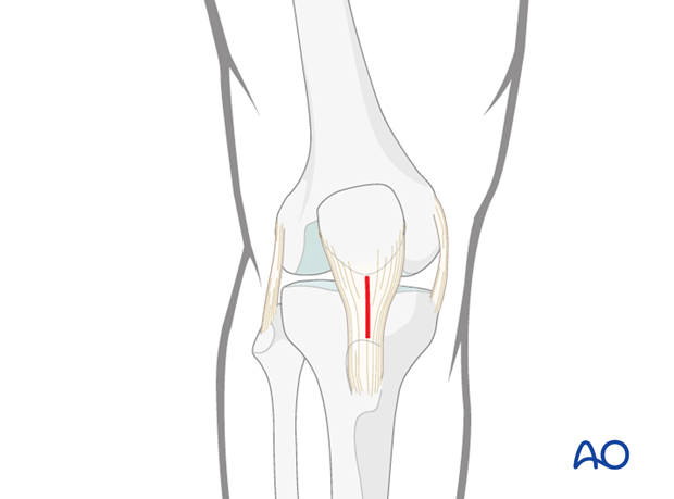
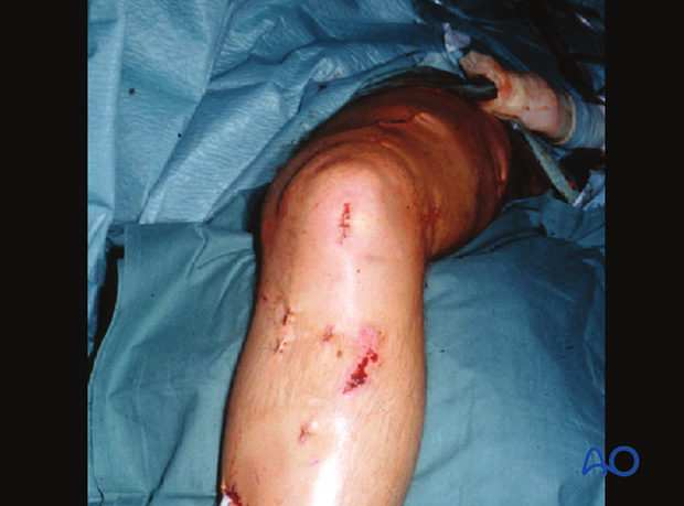
A 2 cm skin incision is made longitudinally just distal to the inferior patellar pole, over the midline of the patellar tendon.
Clinical image of the skin incision.
3. Dissection
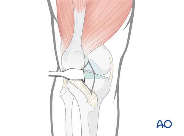
The medial parapatellar soft tissues are spread longitudinally with scissors. The patellar tendon is gently retracted laterally to allow for guide wire insertion.
The approach may alternatively involve splitting of the patellar tendon.
4. Localization of the entry point
It is very important to perform every step of the process of locating the entry point under image intensifier guidance.
- On the AP view, the guide wire should be centered exactly in the middle of the intercondylar notch.
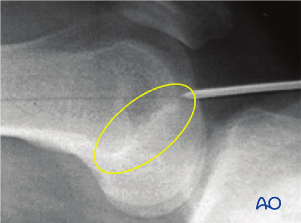
- On the lateral view it should be located in the extension of Blumensaat’s line.
- The entry point of the nail is in line with the axis of the medullary canal, just below the crest of the intercondylar notch.
The correct position is therefore located anterior and lateral to the proximal attachment of the posterior cruciate ligament.
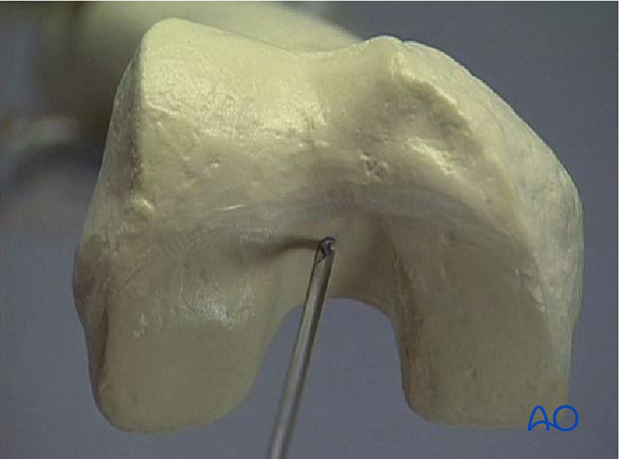
Care must be taken not to establish the entry point posterior to the Blumensaat’s line, to prevent damage to the anterior cruciate ligament upon reaming.
The x-ray shows the desired 30° flexion of the knee joint. With less flexion the tibial plateau hinders the guide wire insertion. With more flexion the articular surface is in danger and the patella is in the way.
Once the correct entry point is determined, a guide wire is inserted 3–4 cm.
5. Opening the medullary canal
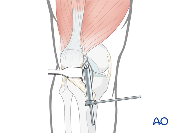
To open the medullary canal, the protection sleeve and drill sleeve are pushed over the guide wire into the notch, and the medullary canal is opened to a depth of approximately 30 mm using the cannulated drill bit.
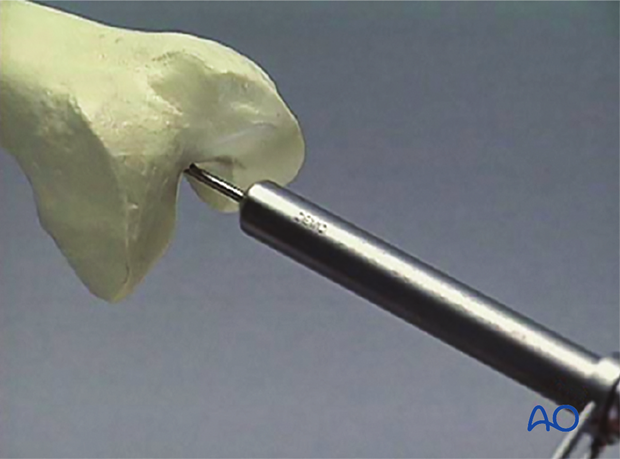
The drill bit, protection sleeve and guide wire are then removed.
The knee joint is carefully irrigated to remove all drilling debris.
