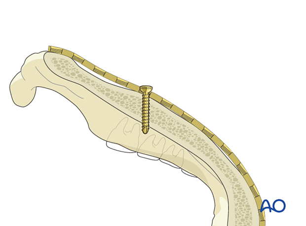
Screw insertion into locking plates
1. Principles
Locking plates allow for the insertion of two different types of screws:
- Locking screws
- Nonlocking screws
Generally, locking screws are preferred because there is less chance of the screw loosening.
Further advantages of locking screws compared to nonlocking screws can be found here.
Depending on the manufacturer, locking screws may need to be placed at a right angle to the plate and centered to allow the threaded screw head to engage with the thread in the plate.
Different locking plate shapes and sizes are available.
When inserting a nonlocking screw in a locking plate, up to 30° of angulation is possible. The need for angled screw insertion depends on fracture anatomy and the requirements for screw fixation.
Generally, locking screws and conventional screws are self-tapping. On rare occasions, tapping may be desirable when the surgeon encounters unusually dense or sclerotic cortical bone, such as in the atrophic edentulous mandible.
Tapping is accomplished using a bone tap instrument.
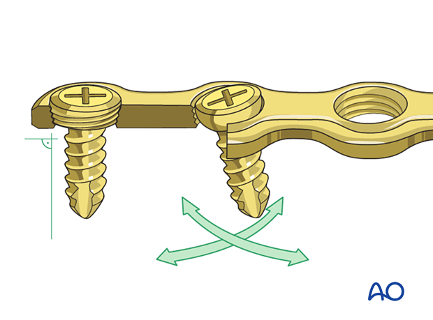
These 3D models allow bending of locking screws and conventional screws to be simulated.
The fixed angle locking construct (bottom panel) provides considerable stability and there is bending of both the screw and the plate. In contrast, the conventional screw (top panel) can freely rotate in its plate hole without causing deformation.
High stress is shown in red and low stress is shown in green.
2. Insertion of monocortical locking and nonlocking screws into a locking miniplate
When using a locking screw, use a threaded drill guide to keep the drill in the center of the plate hole and perfectly perpendicular to the plate so that the screw head can lock evenly.
Drill the hole with the appropriate-sized drill bit.
Monocortically inserted screws are generally drilled to a depth of 5–6 mm. Stop drilling once loss of resistance from the outer cortex is felt.
Use copious irrigation to prevent over-heating of the bone.
Insert the screws using a screwdriver.
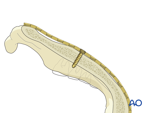
Locking screws lock into the threaded holes of the locking plate as they are inserted.
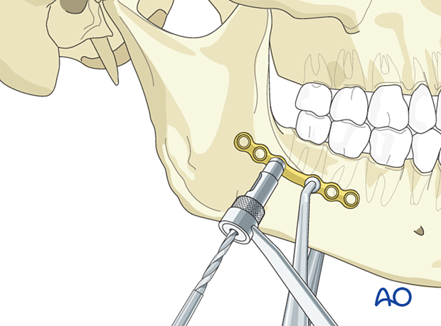
3. Insertion of bicortical locking screws into a locking plate
Drilling the hole
When using a locking screw, use the threaded drill guide to keep the drill in the center of the plate hole and perfectly perpendicular to the plate so that the screw head can lock evenly.
Threaded drill guides of different lengths are available. The drill guides can be used to manipulate the plate on the mandible and protect the surrounding soft tissues during drilling.
Drill a bicortical hole with the appropriate-sized drill bit. Once the hole has been drilled through the inner cortex, care should be taken to avoid over-drilling and damaging the soft tissue and other structures beyond the inner cortex.
Use copious irrigation to prevent over-heating of the bone.
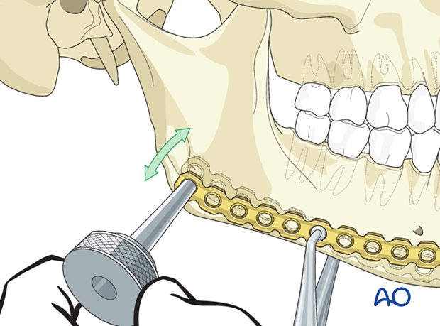
Screw length determination
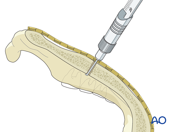
Use a depth gauge to determine the appropriate screw length for bicortical screw insertion.
Screw insertion
Insert the screw using a screwdriver. The screw will stop turning when the threaded screw head is fully engaged into the threaded plate.
4. Insertion of nonlocking screws in a locking screw plate
Drilling the hole
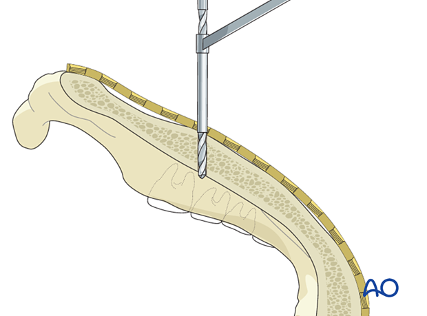
If angulation of the screw is required, the threaded drill guide cannot be used. A non-threaded drill guide can provide correct angulation and protect the surrounding soft tissue during the drilling sequence.
If the screws are to be used bicortically, care should be taken to avoid over-drilling and damaging the soft tissue and other structures beyond the inner cortex.
Use copious irrigation to prevent over-heating of the bone.
Screw length determination
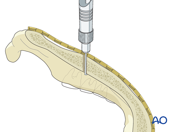
Use a depth gauge to determine the appropriate screw length for screws inserted bicortically.
Screw insertion
Insert the screw using a screwdriver and not a power tool. It is possible to over-tighten the screw and risk displacing the fracture.
Generally, using digital pressure ensures the adequate tightness of the screw.
